1996 CHRYSLER VOYAGER timing belt
[x] Cancel search: timing beltPage 1052 of 1938
made to seal the area between the bedplate and cyl-
inder block without disturbing the bearing clearance
or alignment of these components.
GASKET DISASSEMBLY
Parts assembled with form-in-place gaskets may be
disassembled without unusual effort. In some
instances, it may be necessary to lightly tap the part
with a mallet or other suitable tool to break the seal
between the mating surfaces. A flat gasket scraper
may also be lightly tapped into the joint but care
must be taken not to damage the mating surfaces.
SURFACE PREPARATION
Scrape clean or wire brush all gasket surfaces to
remove all loose material. Inspect stamped parts to
ensure gasket rails are flat. Gasket surfaces must be
free of oil and dirt. Make sure old gasket material is
removed from blind attaching holes.
FORM-IN-PLACE GASKET APPLICATION
Assembling parts using a form-in-place gasket
requires care but it's easier then using precut gas-
kets.
MopartGasket Maker material should be applied
sparingly 1 mm (0.040 in.) diameter or less of sealant
to one gasket surface. Be certain the material sur-
rounds each mounting hole. Excess material can eas-
ily be wiped off. Components should be torqued in
place within 15 minutes. The use of a locating dowel
is recommended during assembly to prevent smear-
ing the material off location.
TheMopartSilicone Rubber Adhesive Sealant
gasket material or equivalent should be applied in a
continuous bead approximately 3 mm (0.120 in.) in
diameter. All mounting holes must be circled. For
corner sealing, a 3.17 or 6.35 mm (1/8 or 1/4 in.) drop
is placed in the center of the gasket contact area.
Uncured sealant may be removed with a shop towels.
Components should be torqued in place while the
sealant is still wet to the touch (within 10 minutes).
The usage of a locating dowel is recommended during
assembly to prevent smearing of material off loca-
tion.
CRANKSHAFT SPROCKET BOLT ACCESS PLUG
An Access plug is located in the right inner fender
shield. Remove the plug and insert the proper size
socket, extension and ratchet, when crankshaft rota-
tion is necessary.
ENGINE CORE PLUGS
REMOVAL
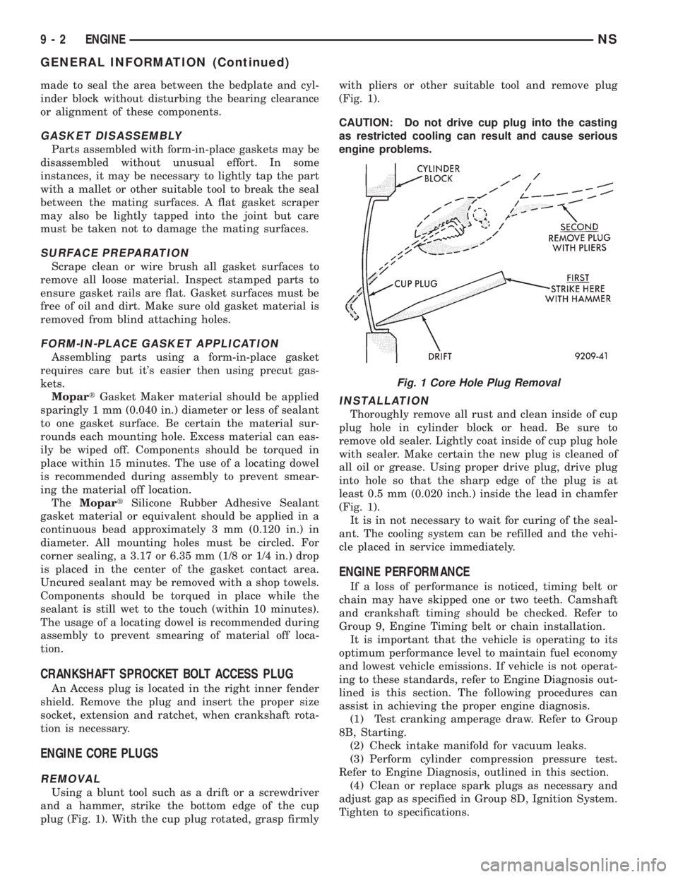
Using a blunt tool such as a drift or a screwdriver
and a hammer, strike the bottom edge of the cup
plug (Fig. 1). With the cup plug rotated, grasp firmlywith pliers or other suitable tool and remove plug
(Fig. 1).
CAUTION: Do not drive cup plug into the casting
as restricted cooling can result and cause serious
engine problems.
INSTALLATION
Thoroughly remove all rust and clean inside of cup
plug hole in cylinder block or head. Be sure to
remove old sealer. Lightly coat inside of cup plug hole
with sealer. Make certain the new plug is cleaned of
all oil or grease. Using proper drive plug, drive plug
into hole so that the sharp edge of the plug is at
least 0.5 mm (0.020 inch.) inside the lead in chamfer
(Fig. 1).
It is in not necessary to wait for curing of the seal-
ant. The cooling system can be refilled and the vehi-
cle placed in service immediately.
ENGINE PERFORMANCE
If a loss of performance is noticed, timing belt or
chain may have skipped one or two teeth. Camshaft
and crankshaft timing should be checked. Refer to
Group 9, Engine Timing belt or chain installation.
It is important that the vehicle is operating to its
optimum performance level to maintain fuel economy
and lowest vehicle emissions. If vehicle is not operat-
ing to these standards, refer to Engine Diagnosis out-
lined is this section. The following procedures can
assist in achieving the proper engine diagnosis.
(1) Test cranking amperage draw. Refer to Group
8B, Starting.
(2) Check intake manifold for vacuum leaks.
(3) Perform cylinder compression pressure test.
Refer to Engine Diagnosis, outlined in this section.
(4) Clean or replace spark plugs as necessary and
adjust gap as specified in Group 8D, Ignition System.
Tighten to specifications.
Fig. 1 Core Hole Plug Removal
9 - 2 ENGINENS
GENERAL INFORMATION (Continued)
Page 1064 of 1938
2.4L ENGINE
INDEX
page page
DESCRIPTION AND OPERATION
ENGINE COMPONENTS.................. 15
ENGINE IDENTIFICATION................. 14
ENGINE LUBRICATION SYSTEM............ 14
DIAGNOSIS AND TESTING
CHECKING ENGINE OIL PRESSURE......... 16
SERVICE PROCEDURES
CRANKSHAFT END PLAY................. 20
FITTING CONNECTING ROD BEARINGS..... 18
FITTING MAIN BEARINGS................. 19
FITTING PISTON RINGS.................. 16
FITTING PISTONS....................... 16
VALVE SERVICE RECONDITION............ 21
REMOVAL AND INSTALLATION
BALANCE SHAFTS CARRIER ASSEMBLY..... 30
CAMSHAFT FOLLOWER.................. 30
CAMSHAFT OIL SEALÐFRONT............. 41
CAMSHAFT............................ 28
CRANKSHAFT OIL SEALÐFRONT........... 42
CRANKSHAFT OIL SEALÐREAR............ 43
CRANKSHAFT.......................... 46
CYLINDER HEAD COVER................. 28
CYLINDER HEAD........................ 34
ENGINE ASSEMBLY...................... 26
ENGINE MOUNTÐFRONT................. 23
ENGINE MOUNTÐLEFT.................. 24
ENGINE MOUNTÐREAR.................. 25
ENGINE MOUNTÐRIGHT................. 24HYDRAULIC LASH ADJUSTER.............. 33
OILFILTER ............................ 47
OILPAN ............................... 45
OIL PUMP............................. 47
PISTON AND CONNECTING ROD........... 49
STRUCTURAL COLLAR................... 25
TIMING BELT COVER.................... 37
TIMING BELT TENSIONER ASSEMBLY....... 40
TIMING BELT........................... 37
VALVE SPRINGS AND
VALVE SEALS IN VEHICLE............... 33
VALVES AND VALVE SPRINGS............. 35
VIBRATION DAMPER.................... 36
DISASSEMBLY AND ASSEMBLY
OIL PUMP............................. 50
CLEANING AND INSPECTION
OIL PUMP............................. 52
CRANKSHAFT.......................... 52
CYLINDER BLOCK....................... 54
CYLINDER HEAD........................ 51
VALVE AND VALVE SPRING................ 51
ADJUSTMENTS
ENGINE MOUNTS....................... 54
SPECIFICATIONS
2.4L ENGINE........................... 55
TORQUE CHART 2.4L.................... 57
SPECIAL TOOLS
2.4L ENGINE........................... 58
DESCRIPTION AND OPERATION
ENGINE IDENTIFICATION
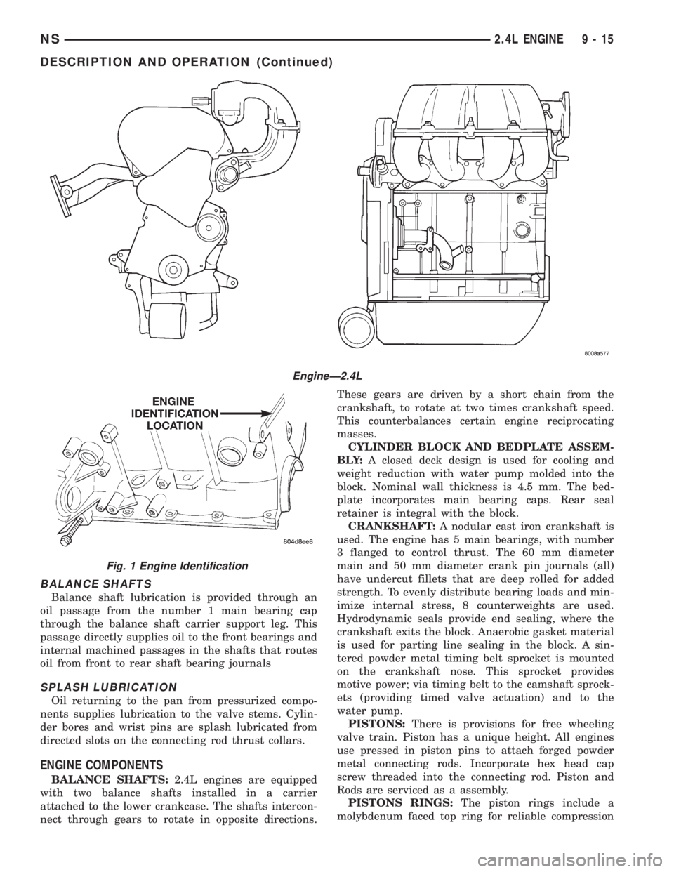
The engine identification number is located on the
rear of the cylinder block (Fig. 1).
ENGINE LUBRICATION SYSTEM
OIL PAN
A structural die cast aluminum oil pan provides
lower engine protection as well as serving as the
engine oil reservoir. Oil pan is attached to block and
sealed with a gasket. The oil pickup tube has a
strainer and cover.
PRESSURE LUBRICATION
Oil drawn up through the pickup tube is pressur-
ized by the pump and routed through the full flow fil-
ter to the main oil gallery running the length of thecylinder block. Oil pickup, pump and check valve pro-
vide oil flow to the main oil gallery.
MAIN/ROD BEARINGS
A diagonal hole in each bulkhead feeds oil to each
main bearing. Drilled passages within the crankshaft
route oil from main bearing journals to connecting
rod journals.
CAMSHAFT/HYDRAULIC LASH ADJUSTERS
A vertical hole at the number five bulkhead routes
pressurized oil through a restrictor up past a cylin-
der head bolt to an oil gallery running the length of
the cylinder head. The camshaft journals are par-
tially slotted to allow a predetermined amount of
pressurized oil to pass into the bearing cap cavities
with small holes directed to spray lubricate the cam-
shaft lobes.
9 - 14 2.4L ENGINENS
Page 1065 of 1938
BALANCE SHAFTS
Balance shaft lubrication is provided through an
oil passage from the number 1 main bearing cap
through the balance shaft carrier support leg. This
passage directly supplies oil to the front bearings and
internal machined passages in the shafts that routes
oil from front to rear shaft bearing journals
SPLASH LUBRICATION
Oil returning to the pan from pressurized compo-
nents supplies lubrication to the valve stems. Cylin-
der bores and wrist pins are splash lubricated from
directed slots on the connecting rod thrust collars.
ENGINE COMPONENTS
BALANCE SHAFTS:2.4L engines are equipped
with two balance shafts installed in a carrier
attached to the lower crankcase. The shafts intercon-
nect through gears to rotate in opposite directions.These gears are driven by a short chain from the
crankshaft, to rotate at two times crankshaft speed.
This counterbalances certain engine reciprocating
masses.
CYLINDER BLOCK AND BEDPLATE ASSEM-
B LY:A closed deck design is used for cooling and
weight reduction with water pump molded into the
block. Nominal wall thickness is 4.5 mm. The bed-
plate incorporates main bearing caps. Rear seal
retainer is integral with the block.
CRANKSHAFT:A nodular cast iron crankshaft is
used. The engine has 5 main bearings, with number
3 flanged to control thrust. The 60 mm diameter
main and 50 mm diameter crank pin journals (all)
have undercut fillets that are deep rolled for added
strength. To evenly distribute bearing loads and min-
imize internal stress, 8 counterweights are used.
Hydrodynamic seals provide end sealing, where the
crankshaft exits the block. Anaerobic gasket material
is used for parting line sealing in the block. A sin-
tered powder metal timing belt sprocket is mounted
on the crankshaft nose. This sprocket provides
motive power; via timing belt to the camshaft sprock-
ets (providing timed valve actuation) and to the
water pump.
PISTONS:There is provisions for free wheeling
valve train. Piston has a unique height. All engines
use pressed in piston pins to attach forged powder
metal connecting rods. Incorporate hex head cap
screw threaded into the connecting rod. Piston and
Rods are serviced as a assembly.
PISTONS RINGS:The piston rings include a
molybdenum faced top ring for reliable compression
EngineÐ2.4L
Fig. 1 Engine Identification
NS2.4L ENGINE 9 - 15
DESCRIPTION AND OPERATION (Continued)
Page 1078 of 1938
CYLINDER HEAD COVER
REMOVAL
(1) Remove upper intake manifold. Refer to Group
11, Exhaust System and Intake Manifold.
(2) Remove nuts attaching front and rear intake
manifold supports from cylinder head cover attaching
studs.
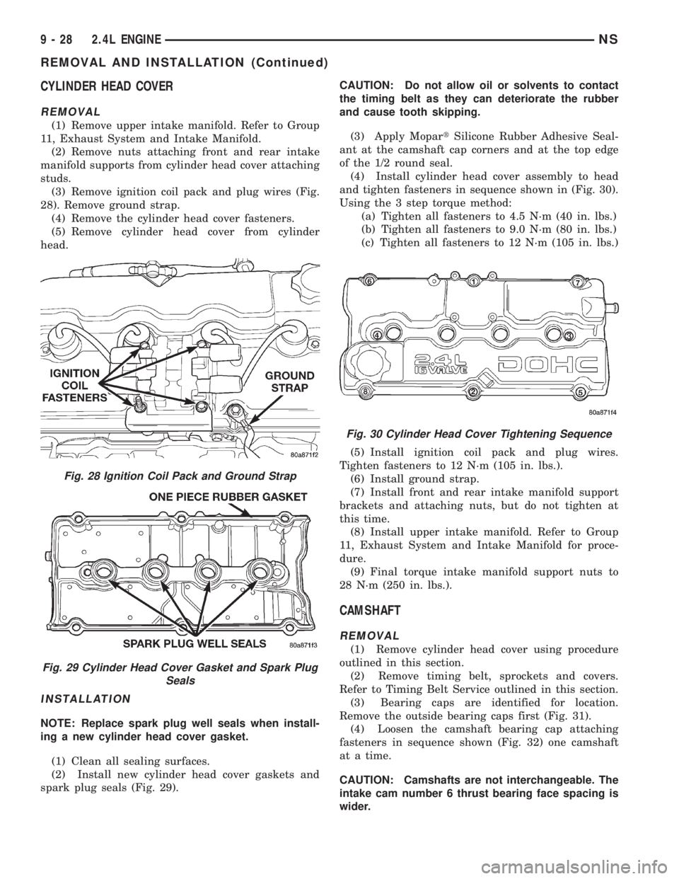
(3) Remove ignition coil pack and plug wires (Fig.
28). Remove ground strap.
(4) Remove the cylinder head cover fasteners.
(5) Remove cylinder head cover from cylinder
head.
INSTALLATION
NOTE: Replace spark plug well seals when install-
ing a new cylinder head cover gasket.
(1) Clean all sealing surfaces.
(2) Install new cylinder head cover gaskets and
spark plug seals (Fig. 29).CAUTION: Do not allow oil or solvents to contact
the timing belt as they can deteriorate the rubber
and cause tooth skipping.
(3) Apply MopartSilicone Rubber Adhesive Seal-
ant at the camshaft cap corners and at the top edge
of the 1/2 round seal.
(4) Install cylinder head cover assembly to head
and tighten fasteners in sequence shown in (Fig. 30).
Using the 3 step torque method:
(a) Tighten all fasteners to 4.5 N´m (40 in. lbs.)
(b) Tighten all fasteners to 9.0 N´m (80 in. lbs.)
(c) Tighten all fasteners to 12 N´m (105 in. lbs.)
(5) Install ignition coil pack and plug wires.
Tighten fasteners to 12 N´m (105 in. lbs.).
(6) Install ground strap.
(7) Install front and rear intake manifold support
brackets and attaching nuts, but do not tighten at
this time.
(8) Install upper intake manifold. Refer to Group
11, Exhaust System and Intake Manifold for proce-
dure.
(9) Final torque intake manifold support nuts to
28 N´m (250 in. lbs.).
CAMSHAFT
REMOVAL
(1) Remove cylinder head cover using procedure
outlined in this section.
(2) Remove timing belt, sprockets and covers.
Refer to Timing Belt Service outlined in this section.
(3) Bearing caps are identified for location.
Remove the outside bearing caps first (Fig. 31).
(4) Loosen the camshaft bearing cap attaching
fasteners in sequence shown (Fig. 32) one camshaft
at a time.
CAUTION: Camshafts are not interchangeable. The
intake cam number 6 thrust bearing face spacing is
wider.
Fig. 28 Ignition Coil Pack and Ground Strap
Fig. 29 Cylinder Head Cover Gasket and Spark Plug
Seals
Fig. 30 Cylinder Head Cover Tightening Sequence
9 - 28 2.4L ENGINENS
REMOVAL AND INSTALLATION (Continued)
Page 1079 of 1938
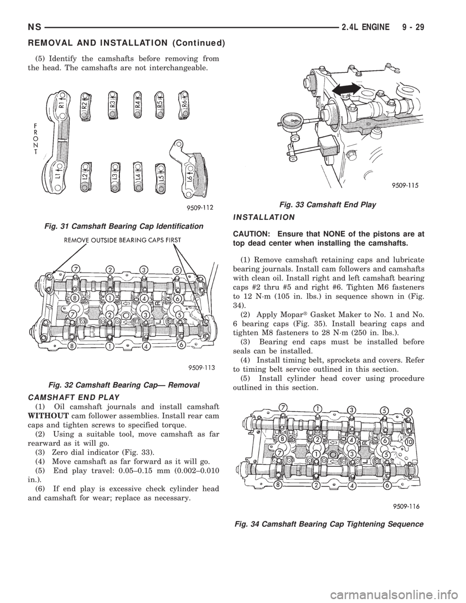
(5) Identify the camshafts before removing from
the head. The camshafts are not interchangeable.
CAMSHAFT END PLAY
(1) Oil camshaft journals and install camshaft
WITHOUTcam follower assemblies. Install rear cam
caps and tighten screws to specified torque.
(2) Using a suitable tool, move camshaft as far
rearward as it will go.
(3) Zero dial indicator (Fig. 33).
(4) Move camshaft as far forward as it will go.
(5) End play travel: 0.05±0.15 mm (0.002±0.010
in.).
(6) If end play is excessive check cylinder head
and camshaft for wear; replace as necessary.
INSTALLATION
CAUTION: Ensure that NONE of the pistons are at
top dead center when installing the camshafts.
(1) Remove camshaft retaining caps and lubricate
bearing journals. Install cam followers and camshafts
with clean oil. Install right and left camshaft bearing
caps #2 thru #5 and right #6. Tighten M6 fasteners
to 12 N´m (105 in. lbs.) in sequence shown in (Fig.
34).
(2) Apply MopartGasket Maker to No. 1 and No.
6 bearing caps (Fig. 35). Install bearing caps and
tighten M8 fasteners to 28 N´m (250 in. lbs.).
(3) Bearing end caps must be installed before
seals can be installed.
(4) Install timing belt, sprockets and covers. Refer
to timing belt service outlined in this section.
(5) Install cylinder head cover using procedure
outlined in this section.Fig. 31 Camshaft Bearing Cap Identification
Fig. 32 Camshaft Bearing CapÐ Removal
Fig. 33 Camshaft End Play
Fig. 34 Camshaft Bearing Cap Tightening Sequence
NS2.4L ENGINE 9 - 29
REMOVAL AND INSTALLATION (Continued)
Page 1080 of 1938
CAMSHAFT FOLLOWER
REMOVAL
(1) Remove cylinder head cover using procedure
outlined in this section.
(2) Remove timing belt, sprockets and covers
using procedure outlined in this section.
(3) Remove camshaft. Refer to procedure previ-
ously outline this section.
(4) Remove cam follower assemblies from cylinder
head. Keep the cam followers in the order they have
been removed from the head for reassembly.
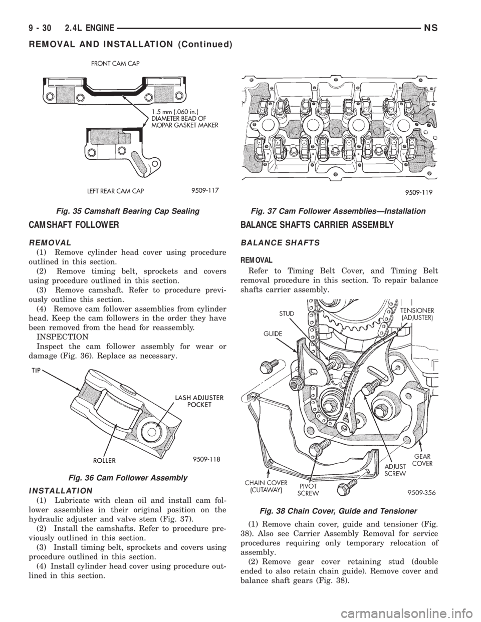
INSPECTION
Inspect the cam follower assembly for wear or
damage (Fig. 36). Replace as necessary.
INSTALLATION
(1) Lubricate with clean oil and install cam fol-
lower assemblies in their original position on the
hydraulic adjuster and valve stem (Fig. 37).
(2) Install the camshafts. Refer to procedure pre-
viously outlined in this section.
(3) Install timing belt, sprockets and covers using
procedure outlined in this section.
(4) Install cylinder head cover using procedure out-
lined in this section.
BALANCE SHAFTS CARRIER ASSEMBLY
BALANCE SHAFTS
REMOVAL
Refer to Timing Belt Cover, and Timing Belt
removal procedure in this section. To repair balance
shafts carrier assembly.
(1) Remove chain cover, guide and tensioner (Fig.
38). Also see Carrier Assembly Removal for service
procedures requiring only temporary relocation of
assembly.
(2) Remove gear cover retaining stud (double
ended to also retain chain guide). Remove cover and
balance shaft gears (Fig. 38).
Fig. 35 Camshaft Bearing Cap Sealing
Fig. 36 Cam Follower Assembly
Fig. 37 Cam Follower AssembliesÐInstallation
Fig. 38 Chain Cover, Guide and Tensioner
9 - 30 2.4L ENGINENS
REMOVAL AND INSTALLATION (Continued)
Page 1084 of 1938
CYLINDER HEAD
REMOVAL
(1) Perform fuel system pressure release proce-
durebefore attempting any repairs.Refer to
Group 14, Fuel System for procedure.
(2) Disconnect negative battery cable. Drain cool-
ing system. Refer to Group 7, Cooling System for pro-
cedure.
(3) Remove air cleaner and disconnect all vacuum
lines, electrical wiring and fuel lines from throttle
body.
(4) Remove throttle linkage. Refer to Group 14,
Fuel System for procedures
(5) Remove accessory drive belts. Refer to Group
7, Cooling System for procedure.
(6) Remove power brake vacuum hose from intake
manifold.
(7) Raise vehicle and remove exhaust pipe from
manifold.(8) Remove power steering pump assembly and
set aside.
(9) Disconnect coil pack wiring connector and
remove coil pack and plug wires from engine.
(10) Remove cam sensor and fuel injectors wiring
connectors.
(11) Remove timing belt and camshaft sprocket.
Refer to procedure outlined in this section.
(12) Remove timing belt idler pulley and rear tim-
ing belt cover.
(13) Remove cylinder head cover using procedure
outlined in this section.
(14) Remove camshafts and cam followers. Refer to
procedures outlined in this section for procedures.
(15) Remove cylinder head bolts and remove cyl-
inder head from engine block.
(16) Inspect and clean cylinder head. Refer to
Cleaning and Inspection outlined in this section for
procedures.
INSTALLATION
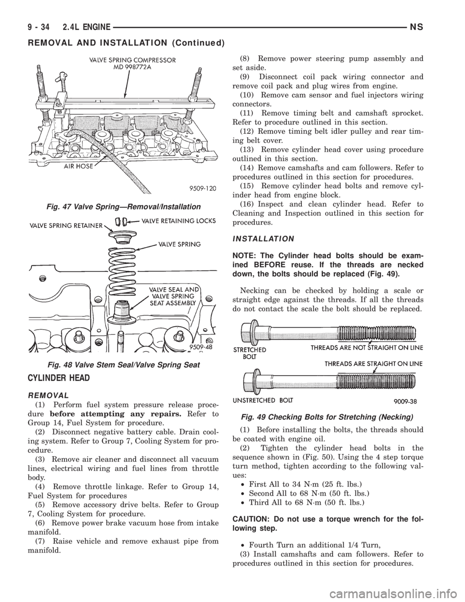
NOTE: The Cylinder head bolts should be exam-
ined BEFORE reuse. If the threads are necked
down, the bolts should be replaced (Fig. 49).
Necking can be checked by holding a scale or
straight edge against the threads. If all the threads
do not contact the scale the bolt should be replaced.
(1) Before installing the bolts, the threads should
be coated with engine oil.
(2) Tighten the cylinder head bolts in the
sequence shown in (Fig. 50). Using the 4 step torque
turn method, tighten according to the following val-
ues:
²First All to 34 N´m (25 ft. lbs.)
²Second All to 68 N´m (50 ft. lbs.)
²Third All to 68 N´m (50 ft. lbs.)
CAUTION: Do not use a torque wrench for the fol-
lowing step.
²Fourth Turn an additional 1/4 Turn,
(3) Install camshafts and cam followers. Refer to
procedures outlined in this section for procedures.
Fig. 47 Valve SpringÐRemoval/Installation
Fig. 48 Valve Stem Seal/Valve Spring Seat
Fig. 49 Checking Bolts for Stretching (Necking)
9 - 34 2.4L ENGINENS
REMOVAL AND INSTALLATION (Continued)
Page 1085 of 1938
(4) Install cylinder head cover using procedure out-
lined in this section.
(5) Install rear timing belt cover and timing belt
idler pulley.
(6) Install timing belt and camshaft sprocket.
Refer to procedure outlined in this section.
(7) Install cam sensor and fuel injectors wiring
connectors.
(8) Install coil pack and plug wires onto the
engine. Connect coil pack wiring connector.
(9) Install power steering pump assembly.
(10) Raise vehicle and install the exhaust pipe to
the manifold.
(11) Install power brake vacuum hose to the intake
manifold.
(12) Install accessory drive belts. Refer to Group 7,
Cooling System for procedure.
(13) Install throttle linkage. Refer to Group 14,
Fuel System for procedures.
(14) Install air cleaner and connect all vacuum
lines, electrical wiring and fuel lines to the throttle
body.
(15) Fill cooling system. Refer to Group 7, Cooling
System for procedure. Connect negative battery
cable.
VALVES AND VALVE SPRINGS
REMOVAL
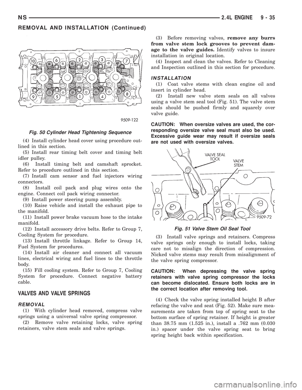
(1) With cylinder head removed, compress valve
springs using a universal valve spring compressor.
(2) Remove valve retaining locks, valve spring
retainers, valve stem seals and valve springs.(3) Before removing valves,remove any burrs
from valve stem lock grooves to prevent dam-
age to the valve guides.Identify valves to insure
installation in original location.
(4) Inspect and clean the valves. Refer to Cleaning
and Inspection outlined in this section for procedure.
INSTALLATION
(1) Coat valve stems with clean engine oil and
insert in cylinder head.
(2) Install new valve stem seals on all valves
using a valve stem seal tool (Fig. 51). The valve stem
seals should be pushed firmly and squarely over
valve guide.
CAUTION: When oversize valves are used, the cor-
responding oversize valve seal must also be used.
Excessive guide wear may result if oversize seals
are not used with oversize valves.
(3) Install valve springs and retainers. Compress
valve springs only enough to install locks, taking
care not to misalign the direction of compression.
Nicked valve stems may result from misalignment of
the valve spring compressor.
CAUTION: When depressing the valve spring
retainers with valve spring compressor the locks
can become dislocated. Ensure both locks are in
the correct location after removing tool.
(4) Check the valve spring installed height B after
refacing the valve and seat (Fig. 52). Make sure mea-
surements are taken from top of spring seat to the
bottom surface of spring retainer. If height is greater
than 38.75 mm (1.525 in.), install a .762 mm (0.030
in.) spacer under the valve spring seat to bring
spring height back within specification.
Fig. 50 Cylinder Head Tightening Sequence
Fig. 51 Valve Stem Oil Seal Tool
NS2.4L ENGINE 9 - 35
REMOVAL AND INSTALLATION (Continued)