1996 CHRYSLER VOYAGER timing belt
[x] Cancel search: timing beltPage 1214 of 1938
Valve Margin
Intake.....1.15 ± 1.48 mm (0.0452 ± 0.0582 in.)
Exhaust....1.475 ± 1.805 mm (0.058 ± 0.071 in.)
Valve Length (Overall)
Intake....114.69 ± 115.19 mm (4.515 ± 4.535 in.)
Exhaust . . 109.59 ± 110.09 mm (4.603 ± 4.623 in.)
Valve Stem Tip Height
Intake.......45.01 ± 46.07 mm (1.77 ± 1.81 in.)
Exhaust......43.51 ± 44.57 mm (1.71 ± 1.75 in.)
Stem Diameter
Intake.....5.934 ± 5.952 mm (0.234 ± 0.234 in.)
Exhaust....5.906 ± 5.924 mm (0.233 ± 0.233 in.)
Stem to Guide Clearance
Intake . . . 0.048 ± 0.066 mm (0.0018 ± 0.0025 in.)
Exhaust . 0.0736 ± 0.094 mm (0.0029 ± 0.0037 in.)
Max. Allowable Intake.....0.076 mm (0.003 in.)
Max. Allowable Exhaust....0.101 mm (0.004 in.)
Valve Springs
Free Length (Approx.)......44.4 mm (1.747 in.)
Nominal Force (Valve closed) . 91 N´m @ 39.8 mm
(67 ft. lbs. @ 1.57 in.)
Nominal Force (Valve open) . 239 N´m @ 32.6 mm
(176 lbs. @ 1.28 in.)
Installed Height..........40.18 mm (1.580 in.)
* SERVICE AS AN ASSEMBLY WITH ROCKER
ARM.
** ALL READINGS IN CRANKSHAFT DEGREES,
AT 0.5 mm (0.019 in.) OF VALVE LIFT.
TORQUE CHART 2.0L SOHC
DESCRIPTION...................TORQUE
Camshaft Sensor Pick Up
Bolts...................9.6N´m(85in.lbs.)
Camshaft Sprocket
Bolt....................115N´m(85ft.lbs.)
Connecting Rod Cap
Bolts.........27N´m(20ft.lbs.) Plus 1/4 Turn
CollarÐOil Pan to Transaxle
Step 1: Collar to Oil Pan Bolts . 3 N´m (30 in. lbs.)
Step 2: Collar to Transaxle
Bolts...................108N´m(80ft.lbs.)
Step 3: Collar to Oil Pan
Bolts....................54N´m(40ft.lbs.)
Crankshaft Main Bearing Cap/Bedplate
M8 Bedplate Bolts..........30N´m(22ft.lbs.)
M11 Main Cap Bolts........81N´m(60ft.lbs.)
Crankshaft Damper
Bolt...................142N´m(105 ft. lbs.)
Cylinder Head
Bolts.......Refer To Cylinder Head Installation
Cylinder Head Cover
Bolts...................12N´m(105 in. lbs.)
Engine Mount BracketÐRight
Bolts....................61N´m(45ft.lbs.)DESCRIPTION...................TORQUE
Engine Mounting
Bolts.......Refer to Engine Mount Installation
Exhaust Manifold to Cylinder Head
Bolts...................23N´m(200 in. lbs.)
Exhaust Manifold Heat Shield
Bolts...................12N´m(105 in. lbs.)
Intake Manifold
Bolts...................12N´m(105 in. lbs.)
Oil Filter Adapter
Fastener.................80N´m(60ft.lbs.)
Oil Filter.................20N´m(15ft.lbs.)
Oil Pan
Bolts...................12N´m(105 in. lbs.)
Drain Plug...............27N´m(20ft.lbs.)
Oil Pump Attaching
Bolts...................28N´m(250 in. lbs.)
Oil Pump Cover Fastener . . . 12 N´m (105 in. lbs.)
Oil Pump Pick-up Tube Bolt . 28 N´m (250 in. lbs.)
Oil Pump Relief Valve Cap . . . 41 N´m (30 ft. lbs.)
Rocker Arm Shaft
Bolts...................28N´m(250 in. lbs.)
Spark Plugs...............28N´m(20ft.lbs.)
Thermostat Housing
Bolts...................23N´m(200 in lbs.)
Timing Belt Cover
Bolts M6................12N´m(105 in. lbs.)
Timing Belt Mechanical Tensioner Assembly
Bolts...................28N´m(250 in. lbs.)
Timing Belt Hydraulic Tensioner
Pulley Bolt...............68N´m(50ft.lbs.)
Pivot Bracket Bolt..........31N´m(23ft.lbs.)
Tensioner Bolts............31N´m(23ft.lbs.)
Water Pump Mounting
Bolts...................12N´m(105 in. lbs.)
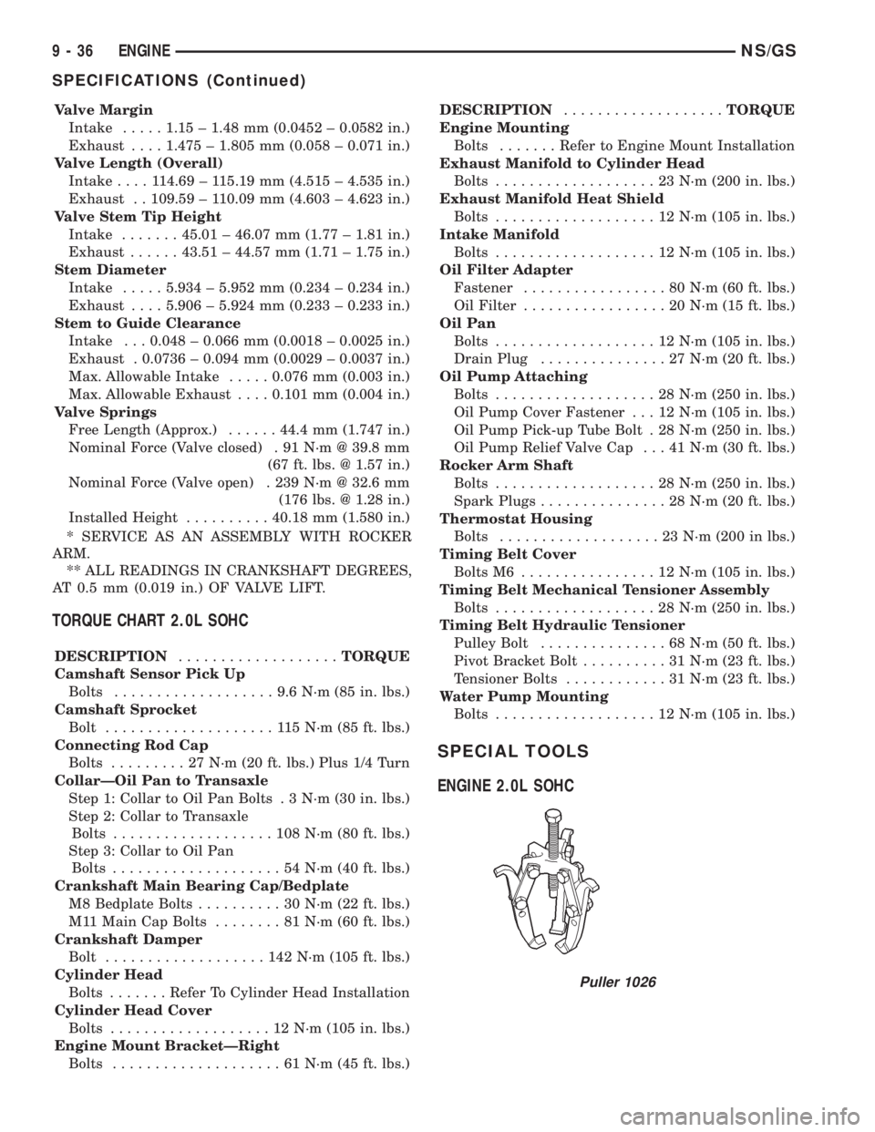
SPECIAL TOOLS
ENGINE 2.0L SOHC
Puller 1026
9 - 36 ENGINENS/GS
SPECIFICATIONS (Continued)
Page 1223 of 1938
ENGINE DIAGNOSISÐMECHANICAL CONT.
CONDITION POSSIBLE CAUSES CORRECTION
LUBRICATING OIL LOSS
(CONT.)6. Turbocharger leaking oil into the
air intake.6. Inspect air duct for evidence of oil
transfer.
7. Piston rings not sealing (oil being
consumed by the engine).7. Perform blow-by check. Repair as
required.
COMPRESSION KNOCKS 1. Air in fuel system. 1. Bleed the fuel system (refer to
Group 14, Fuel System).
2. Poor quality fuel or water/gasoline
contaminated fuel.2. Verify by operating from a
temporary tank with good fuel. Clean
and flush the fuel supply tank.
Replace fuel/water separator.
3. Engine Overloaded. 3. Verify the engine load rating is not
being exceeded.
4. Improperly operating injectors. 4. Check and replace injectors.
5. Fuel injection system defective. 5a. Instrumented injection. 5b. Timing
solenoid of the fuel pump. 5c. Pre
and post heat time of the glow plugs.
Check the fault codes in the ECU.
EXCESSIVE ENGINE NOISES 1. Drive belt squeal, insufficient
tension or abnormally high loading.1. Inspect the drive belts. Make sure
water pump pulley, generator and
power steering all turn freely.
2. Intake air and exhaust leak. 2. Refer to excessive exhaust smoke.
(Engine Diagnosis and Testing)
3. Excessive valve lash. 3. Make sure the rocker arms are not
bent. Defective hydraulic lash
adjuster.
4. Turbocharger noise. 4. Check turbocharger impeller and
turbine wheel for housing contact.
5. Power function knock. 5. Check and replace rod and main
bearings.
6. Fuel injection system defective. 6a. Instrumented injection. 6b. Timing
solenoid of the fuel pump. 6c. Pre
and post heat time of the glow plugs.
Check the fault codes in the ECU.
NS/GSENGINE 9 - 45
DIAGNOSIS AND TESTING (Continued)
Page 1239 of 1938
(3) Install cylinder head, intake manifold, and
exhaust manifold. Refer to cylinder head installation
in this section.
(4) Install push rods in original positions.
(5) Install rocker arms in original positions.
(6) Install cylinder head cover. Refer to cylinder
valve cover installation in this section.
(7) Start and operate engine. Warm up to normal
operating temperature.
CAUTION: To prevent damage to valve mechanism,
engine must not be run above fast idle until all
hydraulic tappets have filled with oil and have
become quiet.
VIBRATION DAMPER
REMOVAL
(1) Disconnect the battery cable.
(2) Raise vehicle on hoist.
(3) Remove right side lower splash shield.
(4) Remove generator, power steering belt. Refer to
Group 7, Cooling.
(5) Remove water pump belt. Refer to Group 7,
Cooling.
(6) Remove engine starter. Refer to Group, 8B for
procedure
(7) Install flywheel locking tool VM.1014 to pre-
vent engine rotation.
NOTE: Crankshaft damper nut is left handed
thread.
(8) Remove vibration damper nut.
(9) Remove vibration damper. No special tool is
needed for removal.
CAUTION: If thread sealant is used it is important
to remove all the old thread sealant from the
threads on the crankshaft.
INSTALLATION
NOTE: Before installing damper be sure the O-ring
inside the center of the damper is in its grove.
(1) Install vibration damper.
CAUTION: Correct torque on the vibration damper
nut is important or engine damage can occur.
(2) Install vibration damper nut and tighten to 441
N´m (325 ft. lbs.).
(3) Remove flywheel locking tool, and install
engine starter.(4) Install both accessary drive belts. Refer to
Group 7, Cooling.
(5) Install right splash shield.
(6) Lower vehicle.
(7) Connect the battery cable.
TIMING GEAR COVER OIL SEAL
REMOVAL
(1) Disconnect the battery cable.
(2) Remove vibration damper. Refer to vibration
damper removal in this section.
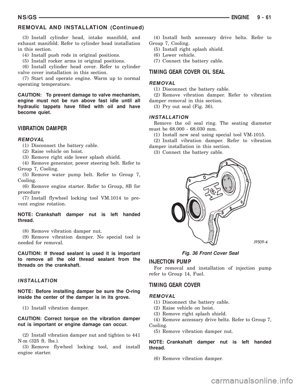
(3) Pry out seal (Fig. 36).
INSTALLATION
Remove the oil seal ring. The seating diameter
must be 68.000 - 68.030 mm.
(1) Install new seal using special tool VM-1015.
(2) Install vibration damper. Refer to vibration
damper installation in this section.
(3) Connect the battery cable.
INJECTION PUMP
For removal and installation of injection pump
refer to Group 14, Fuel.
TIMING GEAR COVER
REMOVAL
(1) Disconnect the battery cable.
(2) Raise vehicle on hoist.
(3) Remove right splash shield.
(4) Remove accessary drive belts. Refer to Group 7,
Cooling.
(5) Remove vibration damper nut.
NOTE: Crankshaft damper nut is left handed
thread.
(6) Remove vibration damper.
Fig. 36 Front Cover Seal
NS/GSENGINE 9 - 61
REMOVAL AND INSTALLATION (Continued)
Page 1240 of 1938
(7) Remove power steering/air conditioning pulley
nut. Remove pulley.
CAUTION: Remove old loctite from threads on
pump.
(8) Remove pump shaft support bracket assembly.
(9) Disconnect the water drain pipe hose at the
timing cover.
CAUTION: When separating the timing geat cover
from the block take care not to damage the mating
surface of the timing gear cover or block. Also take
care not to damage the timing gears or components
located inside the timing gear cover near the edge.
(10) Remove timing gear cover.
INSTALLATION
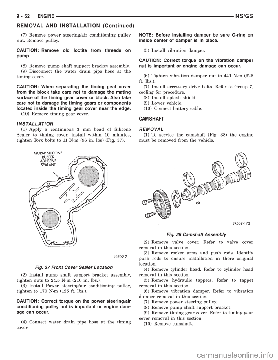
(1) Apply a continuous 3 mm bead of Silicone
Sealer to timing cover, install within 10 minutes,
tighten Torx bolts to 11 N´m (96 in. lbs) (Fig. 37).
(2) Install pump shaft support bracket assembly,
tighten nuts to 24.5 N´m (216 in. lbs.).
(3) Install Power steering/air conditioning pulley,
tighten to 170 N´m (125 ft. lbs.).
CAUTION: Correct torque on the power steering/air
conditioning pulley nut is important or engine dam-
age can occur.
(4) Connect water drain pipe hose at the timing
cover.NOTE: Before installing damper be sure O-ring on
inside center of damper is in place.
(5) Install vibration damper.
CAUTION: Correct torque on the vibration damper
nut is important or engine damage can occur.
(6) Tighten vibration damper nut to 441 N´m (325
ft. lbs.).
(7) Install accessary drive belts. Refer to Group 7,
cooling for procedure.
(8) Install splash shield.
(9) Lower vehicle.
(10) Connect battery cable.
CAMSHAFT
REMOVAL
(1) To service the camshaft (Fig. 38) the engine
must be removed from the vehicle.
(2) Remove valve cover. Refer to valve cover
removal in this section.
(3) Remove rocker arms and push rods. Identify
push rods to ensure installation in there original
location.
(4) Remove cylinder head. Refer to cylinder head
removal in this section.
(5) Remove hydraulic tappets. Refer to tappet
removal in this section.
(6) Remove vibration damper. Refer to vibration
damper removal in this section.
(7) Remove power steering pulley.
(8) Remove pump shaft support bracket.
(9) Remove timing gear cover. Refer to timing gear
cover removal in this section.
(10) Remove camshaft.
Fig. 37 Front Cover Sealer Location
Fig. 38 Camshaft Assembly
9 - 62 ENGINENS/GS
REMOVAL AND INSTALLATION (Continued)
Page 1245 of 1938
(3) Drain oil.
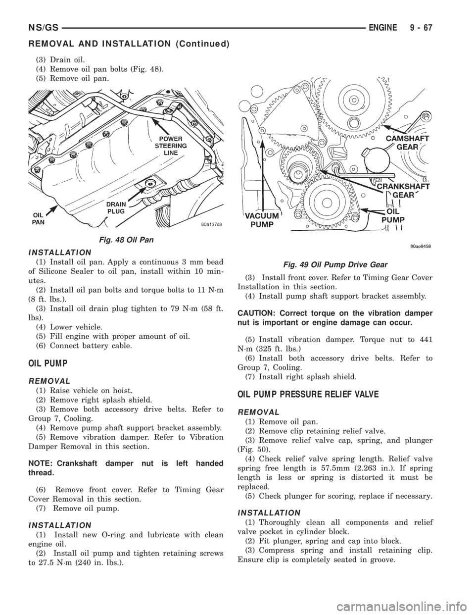
(4) Remove oil pan bolts (Fig. 48).
(5) Remove oil pan.
INSTALLATION
(1) Install oil pan. Apply a continuous 3 mm bead
of Silicone Sealer to oil pan, install within 10 min-
utes.
(2) Install oil pan bolts and torque bolts to 11 N´m
(8 ft. lbs.).
(3) Install oil drain plug tighten to 79 N´m (58 ft.
lbs).
(4) Lower vehicle.
(5) Fill engine with proper amount of oil.
(6) Connect battery cable.
OIL PUMP
REMOVAL
(1) Raise vehicle on hoist.
(2) Remove right splash shield.
(3) Remove both accessory drive belts. Refer to
Group 7, Cooling.
(4) Remove pump shaft support bracket assembly.
(5) Remove vibration damper. Refer to Vibration
Damper Removal in this section.
NOTE: Crankshaft damper nut is left handed
thread.
(6) Remove front cover. Refer to Timing Gear
Cover Removal in this section.
(7) Remove oil pump.
INSTALLATION
(1) Install new O-ring and lubricate with clean
engine oil.
(2) Install oil pump and tighten retaining screws
to 27.5 N´m (240 in. lbs.).(3) Install front cover. Refer to Timing Gear Cover
Installation in this section.
(4) Install pump shaft support bracket assembly.
CAUTION: Correct torque on the vibration damper
nut is important or engine damage can occur.
(5) Install vibration damper. Torque nut to 441
N´m (325 ft. lbs.)
(6) Install both accessory drive belts. Refer to
Group 7, Cooling.
(7) Install right splash shield.
OIL PUMP PRESSURE RELIEF VALVE
REMOVAL
(1) Remove oil pan.
(2) Remove clip retaining relief valve.
(3) Remove relief valve cap, spring, and plunger
(Fig. 50).
(4) Check relief valve spring length. Relief valve
spring free length is 57.5mm (2.263 in.). If spring
length is less or spring is distorted it must be
replaced.
(5) Check plunger for scoring, replace if necessary.
INSTALLATION
(1) Thoroughly clean all components and relief
valve pocket in cylinder block.
(2) Fit plunger, spring and cap into block.
(3) Compress spring and install retaining clip.
Ensure clip is completely seated in groove.
Fig. 48 Oil Pan
Fig. 49 Oil Pump Drive Gear
NS/GSENGINE 9 - 67
REMOVAL AND INSTALLATION (Continued)
Page 1390 of 1938
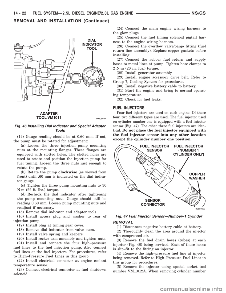
(14) Gauge reading should be at 0.60 mm. If not,
the pump must be rotated for adjustment:
(a) Loosen the three injection pump mounting
nuts at the mounting flanges. These flanges are
equipped with slotted holes. The slotted holes are
used to rotate and position the injection pump for
fuel timing. Loosen the three nuts just enough to
rotate the pump.
(b) Rotate the pumpclockwise(as viewed from
front) until .60 mm is indicated on the dial indica-
tor gauge.
(c) Tighten the three pump mounting nuts to 30
N´m (22 ft. lbs.) torque.
(d) Recheck the dial indicator after tightening
the pump mounting nuts. Gauge should still be
reading 0.60 mm. Loosen pump mounting nuts and
readjust if necessary.
(15) Remove dial indicator and adapter tools.
(16) Install access plug and washer to rear of
injection pump.
(17) Install plug at timing gear cover.
(18) Remove dial indicator from valve stem.
(19) Install valve spring and keepers.
(20) Install rocker arm assembly and tighten nuts.
(21) Install and connect the four high±pressure
fuel lines to the fuel injection pump. Also connect
fuel lines at the fuel injectors. For procedures, refer
to High±Pressure Fuel Lines in this group.
(22) Install electrical connector at engine coolant
temperature sensor.
(23) Connect electrical connector at fuel shutdown
solenoid.(24) Connect the main engine wiring harness to
the glow plugs.
(25) Connect the fuel timing solenoid pigtail har-
ness to the engine wiring harness.
(26) Connect the overflow valve/banjo fitting (fuel
return line assembly). Replace copper gaskets before
installing.
(27) Connect the rubber fuel return and supply
hoses to metal lines at pump. Tighten hose clamps to
2 N´m (20 in. lbs.) torque.
(28) Install generator assembly.
(29) Install engine accessory drive belt. Refer to
Group 7, Cooling System for procedures.
(30) Install negative battery cable to battery.
(31) Start the engine and bring to normal operat-
ing temperature.
(32) Check for fuel leaks.
FUEL INJECTORS
Four fuel injectors are used on each engine. Of these
four, two different types are used. The fuel injector used
on cylinder number one is equipped with a fuel injector
sensor (Fig. 47). The other three fuel injectors are iden-
tical.
Do not place the fuel injector equipped with
the fuel injector sensor into any other location
except the cylinder number one position.
REMOVAL
(1) Disconnect negative battery cable at battery.
(2) Thoroughly clean the area around the injector
with compressed air.
(3) Remove the fuel drain hoses (tubes) at each
injector (Fig. 48) being serviced. Each of these hoses
is slip±fit to the fitting on injector.
(4) Remove the high±pressure fuel line at injector
being removed. Refer to High±Pressure Fuel Lines in
this group for procedures.
(5) Remove the injector using special socket tool
number VM.1012A. When removing cylinder number
Fig. 46 Installing Dial Indicator and Special Adapter
Tools
Fig. 47 Fuel Injector SensorÐNumber±1 Cylinder
14 - 22 FUEL SYSTEMÐ2.5L DIESEL ENGINE/2.0L GAS ENGINENS/GS
REMOVAL AND INSTALLATION (Continued)