1996 CHRYSLER VOYAGER timing belt
[x] Cancel search: timing beltPage 1130 of 1938
c. Lower oil ring side rail.
d. No. 2 Intermediate piston ring.
e. No. 1 Upper piston ring.
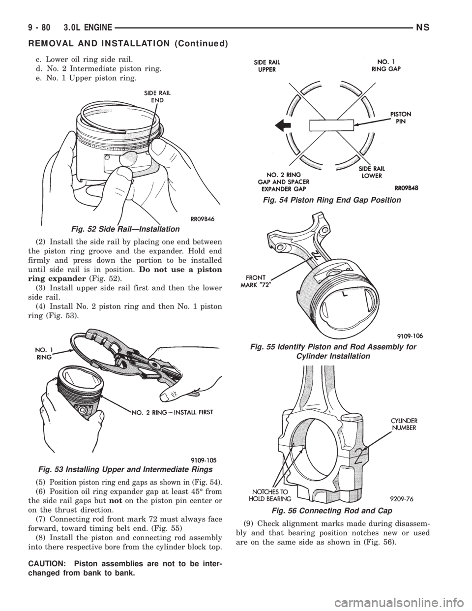
(2) Install the side rail by placing one end between
the piston ring groove and the expander. Hold end
firmly and press down the portion to be installed
until side rail is in position.Do not use a piston
ring expander(Fig. 52).
(3) Install upper side rail first and then the lower
side rail.
(4) Install No. 2 piston ring and then No. 1 piston
ring (Fig. 53).
(5)
Position piston ring end gaps as shown in (Fig. 54).
(6) Position oil ring expander gap at least 45É from
the side rail gaps butnoton the piston pin center or
on the thrust direction.
(7) Connecting rod front mark 72 must always face
forward, toward timing belt end. (Fig. 55)
(8) Install the piston and connecting rod assembly
into there respective bore from the cylinder block top.
CAUTION: Piston assemblies are not to be inter-
changed from bank to bank.(9) Check alignment marks made during disassem-
bly and that bearing position notches new or used
are on the same side as shown in (Fig. 56).
Fig. 52 Side RailÐInstallation
Fig. 53 Installing Upper and Intermediate Rings
Fig. 54 Piston Ring End Gap Position
Fig. 55 Identify Piston and Rod Assembly for
Cylinder Installation
Fig. 56 Connecting Rod and Cap
9 - 80 3.0L ENGINENS
REMOVAL AND INSTALLATION (Continued)
Page 1132 of 1938
CRANKSHAFT BEARINGSÐINSTALLATION
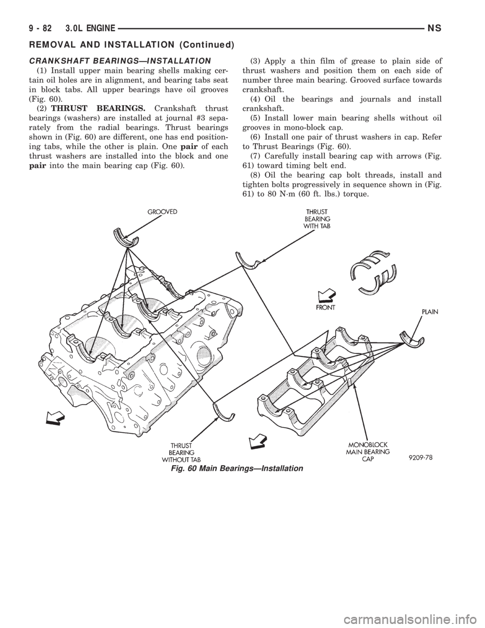
(1) Install upper main bearing shells making cer-
tain oil holes are in alignment, and bearing tabs seat
in block tabs. All upper bearings have oil grooves
(Fig. 60).
(2)THRUST BEARINGS.Crankshaft thrust
bearings (washers) are installed at journal #3 sepa-
rately from the radial bearings. Thrust bearings
shown in (Fig. 60) are different, one has end position-
ing tabs, while the other is plain. Onepairof each
thrust washers are installed into the block and one
pairinto the main bearing cap (Fig. 60).(3) Apply a thin film of grease to plain side of
thrust washers and position them on each side of
number three main bearing. Grooved surface towards
crankshaft.
(4) Oil the bearings and journals and install
crankshaft.
(5) Install lower main bearing shells without oil
grooves in mono-block cap.
(6) Install one pair of thrust washers in cap. Refer
to Thrust Bearings (Fig. 60).
(7) Carefully install bearing cap with arrows (Fig.
61) toward timing belt end.
(8) Oil the bearing cap bolt threads, install and
tighten bolts progressively in sequence shown in (Fig.
61) to 80 N´m (60 ft. lbs.) torque.
Fig. 60 Main BearingsÐInstallation
9 - 82 3.0L ENGINENS
REMOVAL AND INSTALLATION (Continued)
Page 1134 of 1938
OIL PUMP
REMOVAL
1. Remove accessory drive belts. Refer to Accessory
Drive Belts Group 7, Cooling System.
2. Remove Timing Belt. Refer to procedure in this
section.
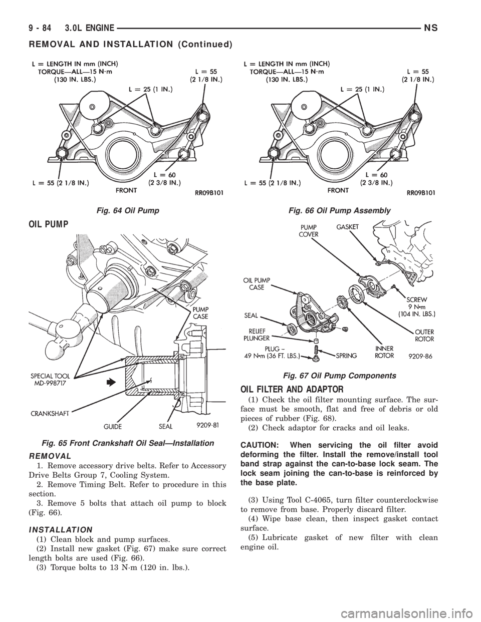
3. Remove 5 bolts that attach oil pump to block
(Fig. 66).
INSTALLATION
(1) Clean block and pump surfaces.
(2) Install new gasket (Fig. 67) make sure correct
length bolts are used (Fig. 66).
(3) Torque bolts to 13 N´m (120 in. lbs.).
OIL FILTER AND ADAPTOR
(1) Check the oil filter mounting surface. The sur-
face must be smooth, flat and free of debris or old
pieces of rubber (Fig. 68).
(2) Check adaptor for cracks and oil leaks.
CAUTION: When servicing the oil filter avoid
deforming the filter. Install the remove/install tool
band strap against the can-to-base lock seam. The
lock seam joining the can-to-base is reinforced by
the base plate.
(3) Using Tool C-4065, turn filter counterclockwise
to remove from base. Properly discard filter.
(4) Wipe base clean, then inspect gasket contact
surface.
(5) Lubricate gasket of new filter with clean
engine oil.
Fig. 64 Oil Pump
Fig. 65 Front Crankshaft Oil SealÐInstallation
Fig. 66 Oil Pump Assembly
Fig. 67 Oil Pump Components
9 - 84 3.0L ENGINENS
REMOVAL AND INSTALLATION (Continued)
Page 1136 of 1938
CLEANING AND INSPECTION
TIMING BELT
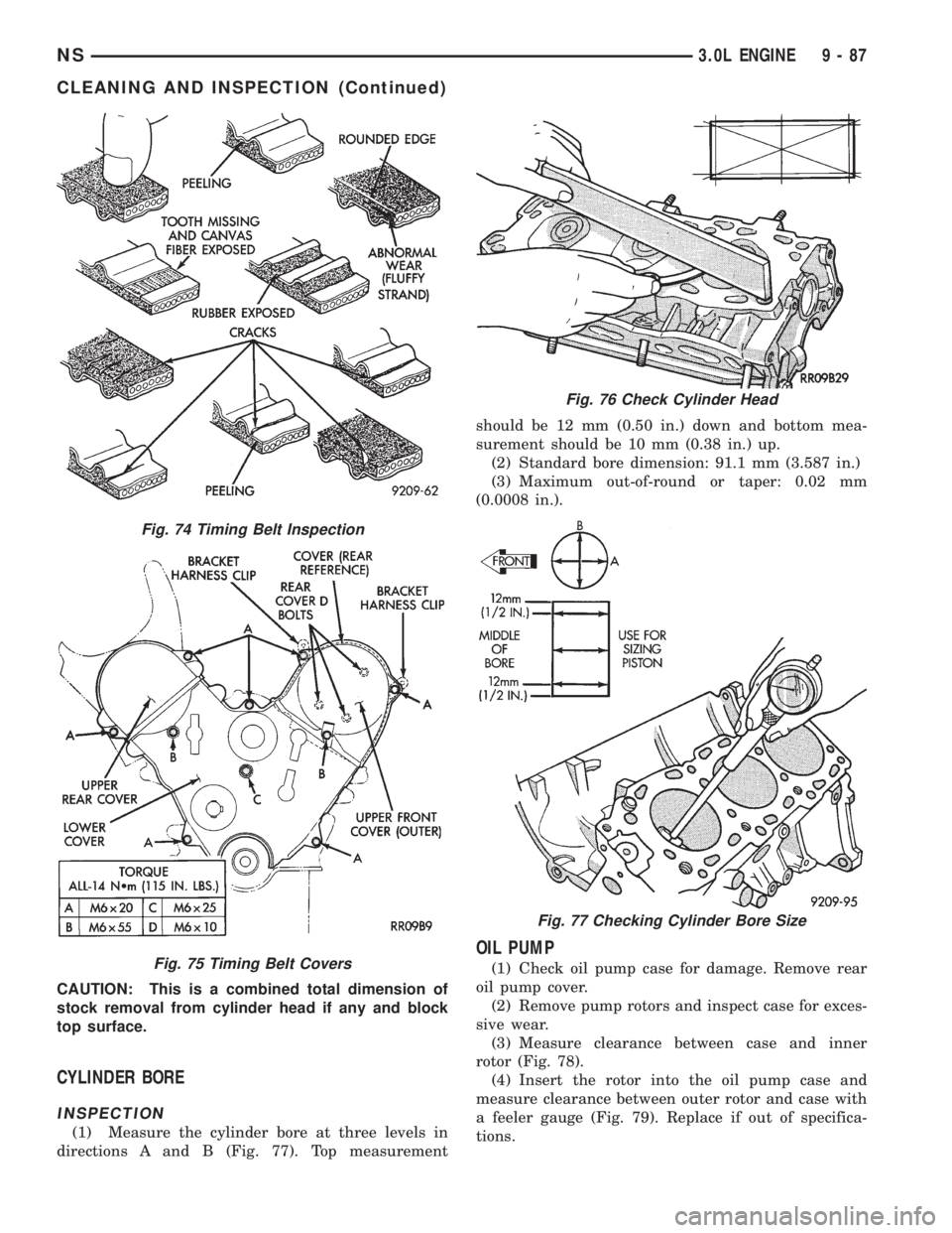
INSPECTION
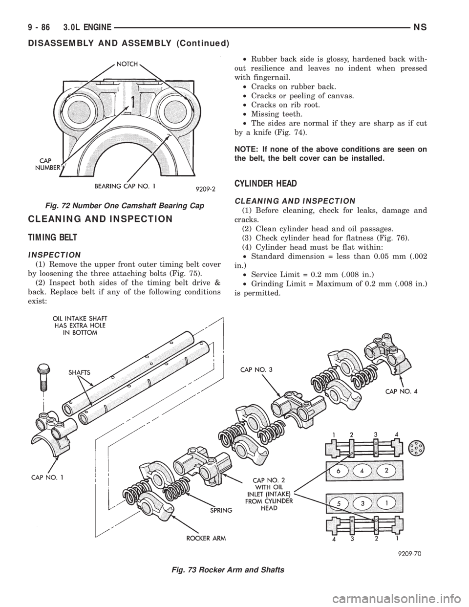
(1) Remove the upper front outer timing belt cover
by loosening the three attaching bolts (Fig. 75).
(2) Inspect both sides of the timing belt drive &
back. Replace belt if any of the following conditions
exist:²Rubber back side is glossy, hardened back with-
out resilience and leaves no indent when pressed
with fingernail.
²Cracks on rubber back.
²Cracks or peeling of canvas.
²Cracks on rib root.
²Missing teeth.
²The sides are normal if they are sharp as if cut
by a knife (Fig. 74).
NOTE: If none of the above conditions are seen on
the belt, the belt cover can be installed.
CYLINDER HEAD
CLEANING AND INSPECTION
(1) Before cleaning, check for leaks, damage and
cracks.
(2) Clean cylinder head and oil passages.
(3) Check cylinder head for flatness (Fig. 76).
(4) Cylinder head must be flat within:
²Standard dimension = less than 0.05 mm (.002
in.)
²Service Limit = 0.2 mm (.008 in.)
²Grinding Limit = Maximum of 0.2 mm (.008 in.)
is permitted.
Fig. 73 Rocker Arm and Shafts
Fig. 72 Number One Camshaft Bearing Cap
9 - 86 3.0L ENGINENS
DISASSEMBLY AND ASSEMBLY (Continued)
Page 1137 of 1938
CAUTION: This is a combined total dimension of
stock removal from cylinder head if any and block
top surface.
CYLINDER BORE
INSPECTION
(1) Measure the cylinder bore at three levels in
directions A and B (Fig. 77). Top measurementshould be 12 mm (0.50 in.) down and bottom mea-
surement should be 10 mm (0.38 in.) up.
(2) Standard bore dimension: 91.1 mm (3.587 in.)
(3) Maximum out-of-round or taper: 0.02 mm
(0.0008 in.).
OIL PUMP
(1) Check oil pump case for damage. Remove rear
oil pump cover.
(2) Remove pump rotors and inspect case for exces-
sive wear.
(3) Measure clearance between case and inner
rotor (Fig. 78).
(4) Insert the rotor into the oil pump case and
measure clearance between outer rotor and case with
a feeler gauge (Fig. 79). Replace if out of specifica-
tions.
Fig. 74 Timing Belt Inspection
Fig. 75 Timing Belt Covers
Fig. 76 Check Cylinder Head
Fig. 77 Checking Cylinder Bore Size
NS3.0L ENGINE 9 - 87
CLEANING AND INSPECTION (Continued)
Page 1140 of 1938
Service Limit.............0.15 mm (0.006 in.)
Valve Guide
Overall Length±Intake........44mm(1.732 in.)
Overall Length±Exhaust.......48mm(1.889 in.)
Outside Diameter...........13.055 - 13.065 mm
(0.514 - 0.5143 in.)
Inside Diameter..............8.000 - 8.018 mm
(0.314 - 315 in.)
Valve Springs
Free Length (Approx.).......49.8 mm (1.960 in.)
Service Limit............48.8 mm (1.9213 in.)
Loaded Height...............40.4 mm @ 33 kg
(1.59 in. @73 lbs.)
Perpendicularity±Intake and Exhaust . . .2É (Max.)
Service Limit.....................4É(Max.)
Oil Pump
Clearance Over Rotors (Max.) .0.077 mm (0.003 in.)
Cover Out-of-Flat (Max.).....0.076 mm (0.003 in.)
Inner Rotor Thickness (Min.) .18.92 mm (0.744 in.)
Outer Rotor (Oil Pump)
Clearance (Max.)...........0.19 mm (0.007 in.)
Diameter (Min.)...........82.45 mm (3.246 in.)
Thickness (Min.)...........18.92 mm (0.744 in.)
Tip Clearance Between Rotors (Max.) . . .0.150 mm
(0.0068 in.)
Oil Pressure
At Curb Idle Speed*...........68.9 kPa (10 psi)
At 3000 rpm.........310 - 517 kPa (45 - 75 psi)
CAUTION: * If pressure is ZERO at curb Idle, DO
NOT run engine at 3,000 rpm.
TORQUE CHART 3.0L
DESCRIPTION TORQUE
Camshaft Bearing Cap
Bolts. . .Refer to procedure outlined in this section.
Camshaft Sensor Pick Up
Bolts.....................27N´m(20ft.lbs.)
Timing Belt Cover
Outer to Inner Attaching Bolts..........4.5 N´m
(40 in. lbs.)
Inner Cover to Head/Oil Pump Bolts.....12N´m
(105 in. lbs.)
Camshaft Sprocket
Bolt......................95N´m(70ft.lbs.)
Connecting Rod Cap
Bolts..........27N´m(20ft.lbs.) Plus 1/4 Turn
Crankshaft Main Bearing Cap/Bedplate
M8 Bedplate Bolts.........34N´m(250 in. lbs.)
M11 Main Cap Bolts..................41N´m
(30 ft. lbs.) Plus 1/4 Turn
Crankshaft Vibration Damper
Bolt....................135 N´m (100 ft. lbs.)DESCRIPTION TORQUE
Cylinder Head
Bolts........Refer To Cylinder Head Installation
Cylinder Head Cover
Bolts....................12N´m(105 in. lbs.)
Engine Mount Bracket
Bolts.....................41N´m(30ft.lbs.)
Engine MountÐFront and Rear
Through Bolt...............61N´m(45ft.lbs.)
Exhaust Manifold to Cylinder Head
Bolts....................23N´m(200 in. lbs.)
Exhaust Manifold Heat Shield
Bolts....................12N´m(105 in. lbs.)
Intake Manifold
Bolts.....................27N´m(20ft.lbs.)
Oil Filter to Engine Block Adapter
Bolts.....................55N´m(40ft.lbs.)
Oil Filter
Filter.....................20N´m(15ft.lbs.)
Oil Pan
Oil Pan Bolts.............12N´m(105 in. lbs.)
Drain Plug.................39N´m(29ft.lbs.)
Oil Pump Attaching
Bolts....................15N´m(130 in. lbs.)
Oil Pump Cover Fastener.....9N´m(104 in. lbs.)
Oil Pump Pick-up Tube Bolt . .28 N´m (250 in. lbs.)
Oil Pump Relief Valve Cap. . . .49 N´m (36 ft. lbs.)
Spark Plugs
Plugs.....................28N´m(20ft.lbs.)
Thermostat Housing
Bolts....................23N´m(200 in lbs.)
Timing Belt Tensioner
Bolt......................28N´m(20ft.lbs.)
Timing Belt Tensioner Pulley Assembly
Bolt......................41N´m(30ft.lbs.)
Water Pump Mounting
Bolts....................12N´m(105 in. lbs.)
9 - 90 3.0L ENGINENS
SPECIFICATIONS (Continued)
Page 1161 of 1938
(6) Start and operate engine. Warm up to normal
operating temperature.
CAUTION: To prevent damage to valve mechanism,
engine must not be run above fast idle until all
hydraulic tappets have filled with oil and have
become quiet.
TIMING CHAIN COVER
REMOVAL
(1) Disconnect negative cable from battery.
(2) Drain cooling system. Refer to Cooling System
Group 7 for procedure.
(3) Support engine and remove right engine
mount.
(4) Raise vehicle on hoist. Drain engine oil.
(5) Remove oil pan and oil pump pick-up. It may
necessary to remove transaxle inspection cover.
(6) Remove right wheel and inner splash shield.
(7) Remove drive belt. Refer to Cooling System
Group 7 for procedure.
(8) Remove A/C compressor and set aside.
(9) Remove A/C compressor mounting bracket.
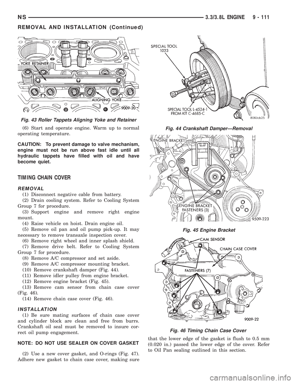
(10) Remove crankshaft damper (Fig. 44).
(11) Remove idler pulley from engine bracket.
(12) Remove engine bracket (Fig. 45).
(13) Remove cam sensor from chain case cover
(Fig. 46).
(14) Remove chain case cover (Fig. 46).
INSTALLATION
(1) Be sure mating surfaces of chain case cover
and cylinder block are clean and free from burrs.
Crankshaft oil seal must be removed to insure cor-
rect oil pump engagement.
NOTE: DO NOT USE SEALER ON COVER GASKET
(2) Use a new cover gasket, and O-rings (Fig. 47).
Adhere new gasket to chain case cover, making surethat the lower edge of the gasket is flush to 0.5 mm
(0.020 in.) passed the lower edge of the cover. Refer
to Oil Pan sealing outlined in this section.
Fig. 43 Roller Tappets Aligning Yoke and Retainer
Fig. 44 Crankshaft DamperÐRemoval
Fig. 45 Engine Bracket
Fig. 46 Timing Chain Case Cover
NS3.3/3.8L ENGINE 9 - 111
REMOVAL AND INSTALLATION (Continued)
Page 1162 of 1938
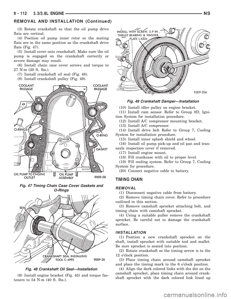
(3) Rotate crankshaft so that the oil pump drive
flats are vertical.
(4) Position oil pump inner rotor so the mating
flats are in the same position as the crankshaft drive
flats (Fig. 47).
(5) Install cover onto crankshaft. Make sure the oil
pump is engaged on the crankshaft correctly or
severe damage may result.
(6) Install chain case cover screws and torque to
27 N´m (20 ft. lbs.).
(7) Install crankshaft oil seal (Fig. 48).
(8) Install crankshaft pulley (Fig. 49).
(9) Install engine bracket (Fig. 45) and torque fas-
teners to 54 N´m (40 ft. lbs.).(10) Install idler pulley on engine bracket.
(11) Install cam sensor. Refer to Group 8D, Igni-
tion System for installation procedure.
(12) Install A/C compressor mounting bracket.
(13) Install A/C compressor.
(14) Install drive belt Refer to Group 7, Cooling
System for installation procedure.
(15) Install inner splash shield and wheel.
(16) Install oil pump pick-up and oil pan and tran-
saxle inspection cover if removed.
(17) Install engine mount.
(18) Fill crankcase with oil to proper level.
(19) Fill cooling system. Refer to Group 7, Cooling
System for procedure.
(20) Connect negative cable to battery.
TIMING CHAIN
REMOVAL
(1) Disconnect negative cable from battery.
(2) Remove timing chain cover. Refer to procedure
outlined in this section.
(3) Remove camshaft sprocket attaching bolt, and
timing chain with camshaft sprocket.
(4) Using a suitable puller remove the crankshaft
sprocket. Be careful not to damage the crankshaft
surface.
INSTALLATION
(1) Position a new crankshaft sprocket on the
shaft, install sprocket with suitable tool and mallet.
Be sure sprocket is seated into position.
(2) Rotate crankshaft so the timing arrow is to the
12 o'clock position.
(3) Place timing chain around camshaft sprocket
and place the timing mark to the 6 o'clock position.
(4) Align the dark colored links with the dot on the
camshaft sprocket, place timing chain around crank-
shaft sprocket with the dark colored link lined up
Fig. 47 Timing Chain Case Cover Gaskets and
O-Rings
Fig. 48 Crankshaft Oil SealÐInstallation
Fig. 49 Crankshaft DamperÐInstallation
9 - 112 3.3/3.8L ENGINENS
REMOVAL AND INSTALLATION (Continued)