1996 CHRYSLER VOYAGER timing belt
[x] Cancel search: timing beltPage 1087 of 1938
TIMING BELT COVER
FRONT COVER
REMOVAL
(1) Remove crankshaft damper. Refer to crank-
shaft damper removal for procedure.
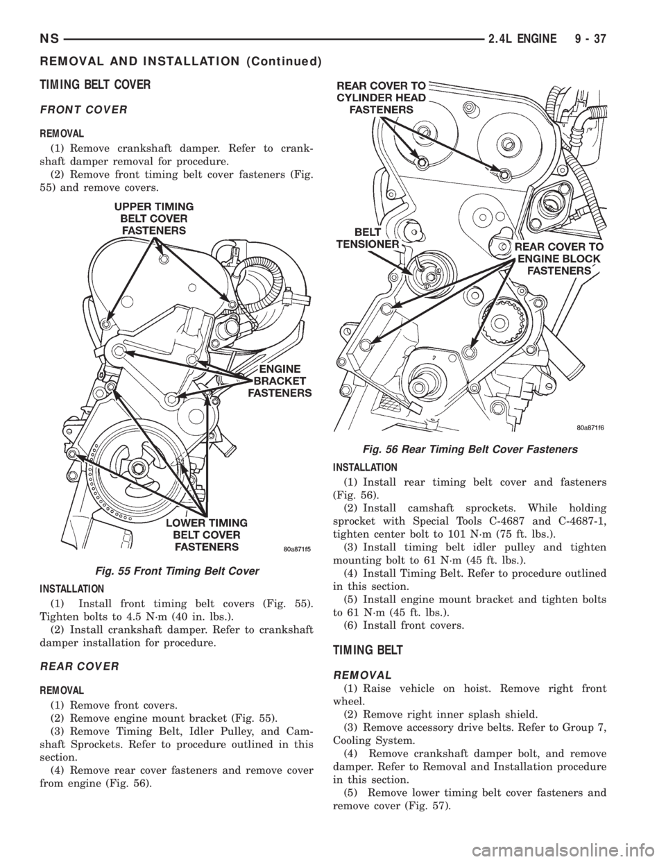
(2) Remove front timing belt cover fasteners (Fig.
55) and remove covers.
INSTALLATION
(1) Install front timing belt covers (Fig. 55).
Tighten bolts to 4.5 N´m (40 in. lbs.).
(2) Install crankshaft damper. Refer to crankshaft
damper installation for procedure.
REAR COVER
REMOVAL
(1) Remove front covers.
(2) Remove engine mount bracket (Fig. 55).
(3) Remove Timing Belt, Idler Pulley, and Cam-
shaft Sprockets. Refer to procedure outlined in this
section.
(4) Remove rear cover fasteners and remove cover
from engine (Fig. 56).INSTALLATION
(1) Install rear timing belt cover and fasteners
(Fig. 56).
(2) Install camshaft sprockets. While holding
sprocket with Special Tools C-4687 and C-4687-1,
tighten center bolt to 101 N´m (75 ft. lbs.).
(3) Install timing belt idler pulley and tighten
mounting bolt to 61 N´m (45 ft. lbs.).
(4) Install Timing Belt. Refer to procedure outlined
in this section.
(5) Install engine mount bracket and tighten bolts
to 61 N´m (45 ft. lbs.).
(6) Install front covers.
TIMING BELT
REMOVAL
(1) Raise vehicle on hoist. Remove right front
wheel.
(2) Remove right inner splash shield.
(3) Remove accessory drive belts. Refer to Group 7,
Cooling System.
(4) Remove crankshaft damper bolt, and remove
damper. Refer to Removal and Installation procedure
in this section.
(5) Remove lower timing belt cover fasteners and
remove cover (Fig. 57).
Fig. 55 Front Timing Belt Cover
Fig. 56 Rear Timing Belt Cover Fasteners
NS2.4L ENGINE 9 - 37
REMOVAL AND INSTALLATION (Continued)
Page 1088 of 1938
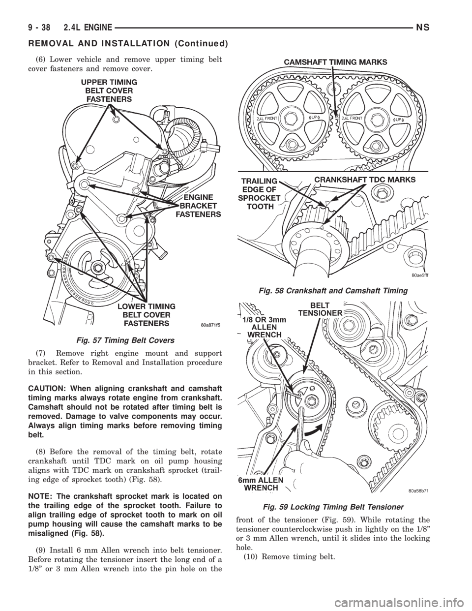
(6) Lower vehicle and remove upper timing belt
cover fasteners and remove cover.
(7) Remove right engine mount and support
bracket. Refer to Removal and Installation procedure
in this section.
CAUTION: When aligning crankshaft and camshaft
timing marks always rotate engine from crankshaft.
Camshaft should not be rotated after timing belt is
removed. Damage to valve components may occur.
Always align timing marks before removing timing
belt.
(8) Before the removal of the timing belt, rotate
crankshaft until TDC mark on oil pump housing
aligns with TDC mark on crankshaft sprocket (trail-
ing edge of sprocket tooth) (Fig. 58).
NOTE: The crankshaft sprocket mark is located on
the trailing edge of the sprocket tooth. Failure to
align trailing edge of sprocket tooth to mark on oil
pump housing will cause the camshaft marks to be
misaligned (Fig. 58).
(9) Install 6 mm Allen wrench into belt tensioner.
Before rotating the tensioner insert the long end of a
1/8º or 3 mm Allen wrench into the pin hole on thefront of the tensioner (Fig. 59). While rotating the
tensioner counterclockwise push in lightly on the 1/8º
or 3 mm Allen wrench, until it slides into the locking
hole.
(10) Remove timing belt.
Fig. 57 Timing Belt Covers
Fig. 58 Crankshaft and Camshaft Timing
Fig. 59 Locking Timing Belt Tensioner
9 - 38 2.4L ENGINENS
REMOVAL AND INSTALLATION (Continued)
Page 1089 of 1938
CAUTION: If timing belt was damaged due to incor-
rect tracking (alignment), the belt tensioner assem-
bly must be replace. Refer to Timing Belt Tensioner
Assembly Removal and Installation procedure out-
lined in this section.
INSTALLATION
(1) Set crankshaft sprocket to TDC by aligning
the sprocket with the arrow on the oil pump housing.
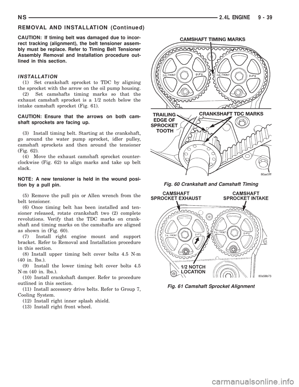
(2) Set camshafts timing marks so that the
exhaust camshaft sprocket is a 1/2 notch below the
intake camshaft sprocket (Fig. 61).
CAUTION: Ensure that the arrows on both cam-
shaft sprockets are facing up.
(3) Install timing belt. Starting at the crankshaft,
go around the water pump sprocket, idler pulley,
camshaft sprockets and then around the tensioner
(Fig. 62).
(4) Move the exhaust camshaft sprocket counter-
clockwise (Fig. 62) to align marks and take up belt
slack.
NOTE: A new tensioner is held in the wound posi-
tion by a pull pin.
(5) Remove the pull pin or Allen wrench from the
belt tensioner.
(6) Once timing belt has been installed and ten-
sioner released, rotate crankshaft two (2) complete
revolutions. Verify that the TDC marks on crank-
shaft and timing marks on the camshafts are aligned
as shown in (Fig. 60).
(7) Install right engine mount and support
bracket. Refer to Removal and Installation procedure
in this section.
(8) Install upper timing belt cover bolts 4.5 N´m
(40 in. lbs.).
(9) Install the lower timing belt cover bolts 4.5
N´m (40 in. lbs.).
(10) Install crankshaft damper. Refer to procedure
outlined in this section.
(11) Install accessory drive belts. Refer to Group 7,
Cooling System.
(12) Install right inner splash shield.
(13) Install right front wheel.
Fig. 60 Crankshaft and Camshaft Timing
Fig. 61 Camshaft Sprocket Alignment
NS2.4L ENGINE 9 - 39
REMOVAL AND INSTALLATION (Continued)
Page 1090 of 1938
TIMING BELT TENSIONER ASSEMBLY
REMOVAL
(1) Remove timing belt. Refer to Removal and
Installation procedure in this section.
(2) Remove timing belt idler pulley.
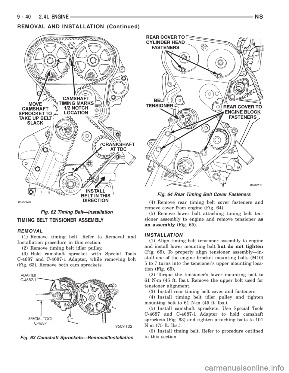
(3) Hold camshaft sprocket with Special Tools
C-4687 and C-4687-1 Adapter, while removing bolt
(Fig. 63). Remove both cam sprockets.(4) Remove rear timing belt cover fasteners and
remove cover from engine (Fig. 64).
(5) Remove lower bolt attaching timing belt ten-
sioner assembly to engine and remove tensioneras
an assembly(Fig. 65).INSTALLATION
(1) Align timing belt tensioner assembly to engine
and install lower mounting boltbut do not tighten
(Fig. 65). To properly align tensioner assemblyÐin-
stall one of the engine bracket mounting bolts (M10)
5 to 7 turns into the tensioner's upper mounting loca-
tion (Fig. 65).
(2) Torque the tensioner's lower mounting bolt to
61 N´m (45 ft. lbs.). Remove the upper bolt used for
tensioner alignment.
(3) Install rear timing belt cover and fasteners.
(4) Install timing belt idler pulley and tighten
mounting bolt to 61 N´m (45 ft. lbs.).
(5) Install camshaft sprockets. Use Special Tools
C-4687 and C-4687-1 Adapter to hold camshaft
sprockets (Fig. 63) and tighten attaching bolts to 101
N´m (75 ft. lbs.).
(6) Install timing belt. Refer to procedure outlined
in this section.
Fig. 62 Timing BeltÐInstallation
Fig. 63 Camshaft SprocketsÐRemoval/Installation
Fig. 64 Rear Timing Belt Cover Fasteners
9 - 40 2.4L ENGINENS
REMOVAL AND INSTALLATION (Continued)
Page 1091 of 1938
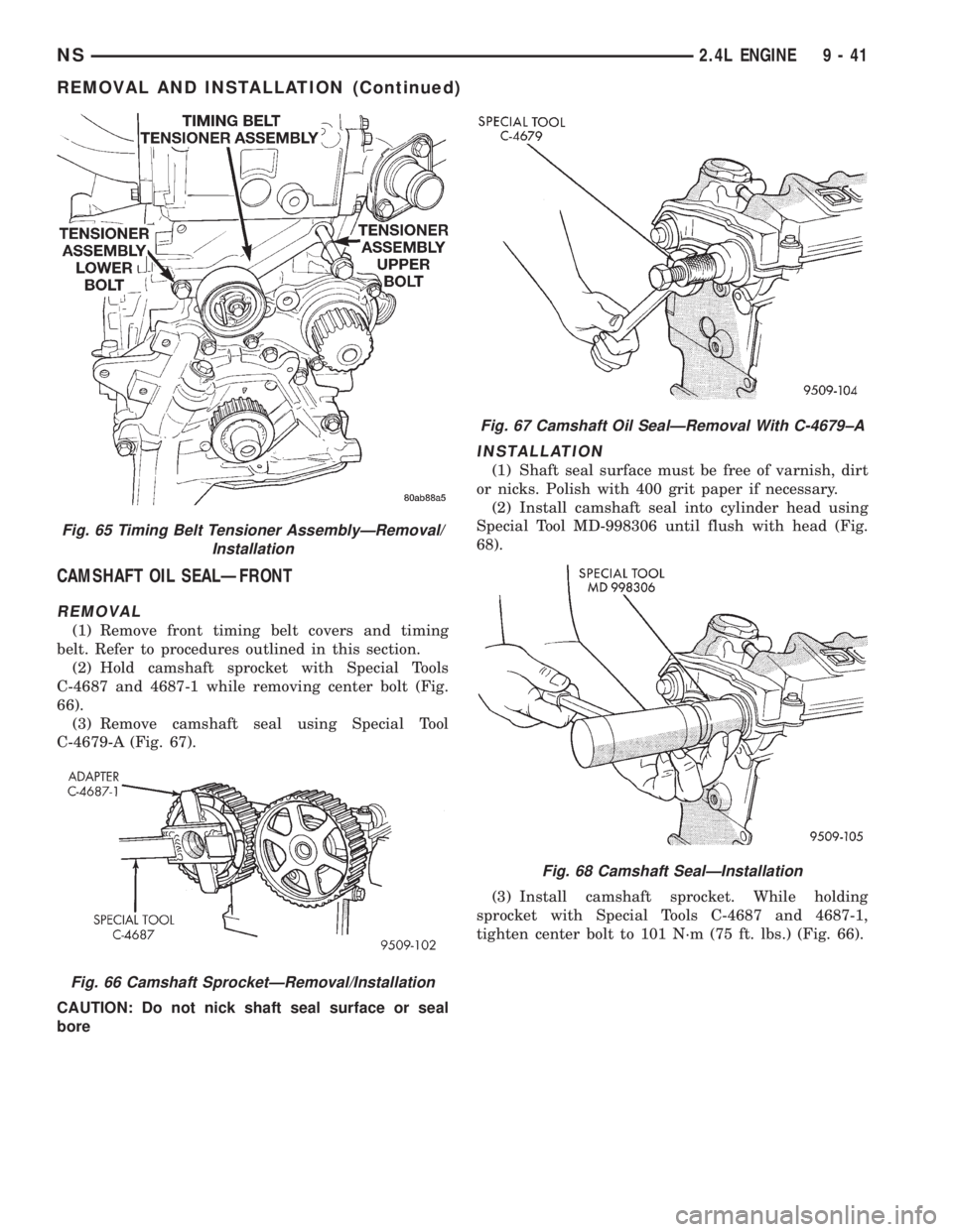
CAMSHAFT OIL SEALÐFRONT
REMOVAL
(1) Remove front timing belt covers and timing
belt. Refer to procedures outlined in this section.
(2) Hold camshaft sprocket with Special Tools
C-4687 and 4687-1 while removing center bolt (Fig.
66).
(3) Remove camshaft seal using Special Tool
C-4679-A (Fig. 67).
CAUTION: Do not nick shaft seal surface or seal
bore
INSTALLATION
(1) Shaft seal surface must be free of varnish, dirt
or nicks. Polish with 400 grit paper if necessary.
(2) Install camshaft seal into cylinder head using
Special Tool MD-998306 until flush with head (Fig.
68).
(3) Install camshaft sprocket. While holding
sprocket with Special Tools C-4687 and 4687-1,
tighten center bolt to 101 N´m (75 ft. lbs.) (Fig. 66).
Fig. 65 Timing Belt Tensioner AssemblyÐRemoval/
Installation
Fig. 66 Camshaft SprocketÐRemoval/Installation
Fig. 67 Camshaft Oil SealÐRemoval With C-4679±A
Fig. 68 Camshaft SealÐInstallation
NS2.4L ENGINE 9 - 41
REMOVAL AND INSTALLATION (Continued)
Page 1092 of 1938
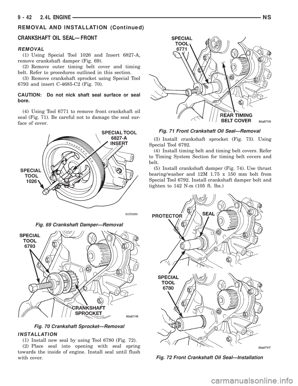
CRANKSHAFT OIL SEALÐFRONT
REMOVAL
(1) Using Special Tool 1026 and Insert 6827-A,
remove crankshaft damper (Fig. 69).
(2) Remove outer timing belt cover and timing
belt. Refer to procedures outlined in this section.
(3) Remove crankshaft sprocket using Special Tool
6793 and insert C-4685-C2 (Fig. 70).
CAUTION: Do not nick shaft seal surface or seal
bore.
(4) Using Tool 6771 to remove front crankshaft oil
seal (Fig. 71). Be careful not to damage the seal sur-
face of cover.
INSTALLATION
(1) Install new seal by using Tool 6780 (Fig. 72).
(2) Place seal into opening with seal spring
towards the inside of engine. Install seal until flush
with cover.(3) Install crankshaft sprocket (Fig. 73). Using
Special Tool 6792.
(4) Install timing belt and timing belt covers. Refer
to Timing System Section for timing belt covers and
belt.
(5) Install crankshaft damper (Fig. 74). Use thrust
bearing/washer and 12M 1.75 x 150 mm bolt from
Special Tool 6792. Install crankshaft damper bolt and
tighten to 142 N´m (105 ft. lbs.)
Fig. 69 Crankshaft DamperÐRemoval
Fig. 70 Crankshaft SprocketÐRemoval
Fig. 71 Front Crankshaft Oil SealÐRemoval
Fig. 72 Front Crankshaft Oil SealÐInstallation
9 - 42 2.4L ENGINENS
REMOVAL AND INSTALLATION (Continued)
Page 1096 of 1938
CRANKSHAFT
REMOVAL
NOTE: Crankshaft can not be removed when
engine is in vehicle.
(1) Remove oil filter and oil pan. Refer to proce-
dure outlined in this section.
(2) Remove Timing Belt Cover, Timing Belt and
Oil Pump. Refer to procedure outlined in this section.
(3) Remove Balance Shafts Assembly. Refer to pro-
cedure outlined in this section.
(4) Remove all main bearing cap bedplate bolts
from the engine block. Refer to procedure outlined in
this section.
(5) Using a mallet gently tap the bedplate loose
from the engine block dowel pins.
CAUTION: Do not pry up on one side of the bed-
plate. Damage may occur to cylinder block to bed-
plate alignment and thrust bearing.
(6) Bedplate should be removed evenly from the
cylinder block dowel pins to prevent damage to the
dowel pins and thrust bearing.
(7) Lift out crankshaft from cylinder block. Do not
damage the main bearings or journals when remov-
ing the crankshaft.
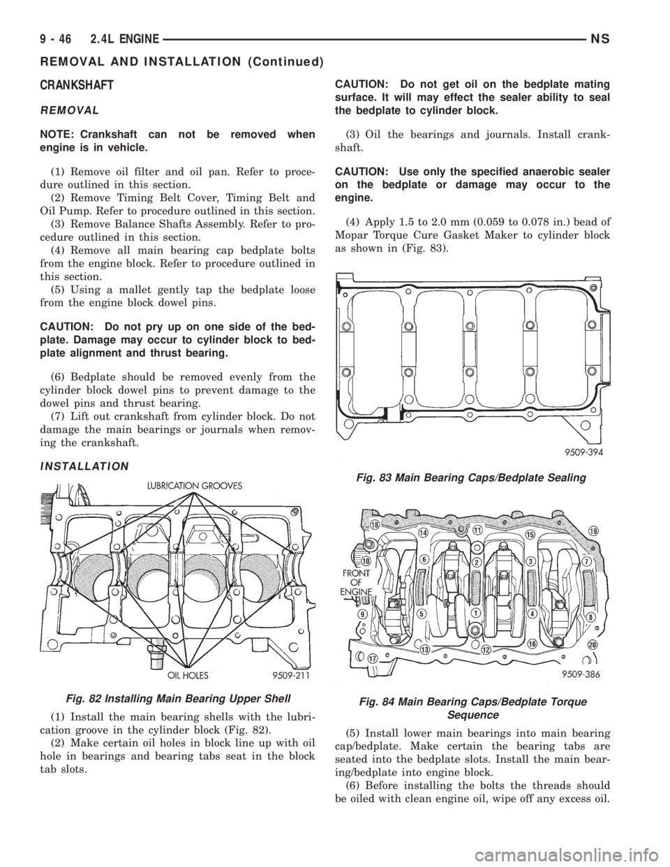
INSTALLATION
(1) Install the main bearing shells with the lubri-
cation groove in the cylinder block (Fig. 82).
(2) Make certain oil holes in block line up with oil
hole in bearings and bearing tabs seat in the block
tab slots.CAUTION: Do not get oil on the bedplate mating
surface. It will may effect the sealer ability to seal
the bedplate to cylinder block.
(3) Oil the bearings and journals. Install crank-
shaft.
CAUTION: Use only the specified anaerobic sealer
on the bedplate or damage may occur to the
engine.
(4) Apply 1.5 to 2.0 mm (0.059 to 0.078 in.) bead of
Mopar Torque Cure Gasket Maker to cylinder block
as shown in (Fig. 83).
(5) Install lower main bearings into main bearing
cap/bedplate. Make certain the bearing tabs are
seated into the bedplate slots. Install the main bear-
ing/bedplate into engine block.
(6) Before installing the bolts the threads should
be oiled with clean engine oil, wipe off any excess oil.
Fig. 82 Installing Main Bearing Upper Shell
Fig. 83 Main Bearing Caps/Bedplate Sealing
Fig. 84 Main Bearing Caps/Bedplate Torque
Sequence
9 - 46 2.4L ENGINENS
REMOVAL AND INSTALLATION (Continued)
Page 1097 of 1938
(7) Install main bearing bedplate to engine block
bolts 11, 17 and 20 finger tight. Tighten these bolts
down together until the bedplate contacts the cylin-
der block.
(8) To ensure correct thrust bearing alignment per-
form the following steps:
²Step 1: Rotate crankshaft until number 4 pis-
ton is at TDC.
²Step 2: Move crankshaft rearward to limits of
travel.
²Step 3: Then, move crankshaft forward to lim-
its of travel.
²Step 4: Wedge an appropraite tool between the
rear of the cylinder block(NOT BED PLATE)and
the rear crankshaft counterweight. This will hold the
crankshaft in it's furthest forward position.
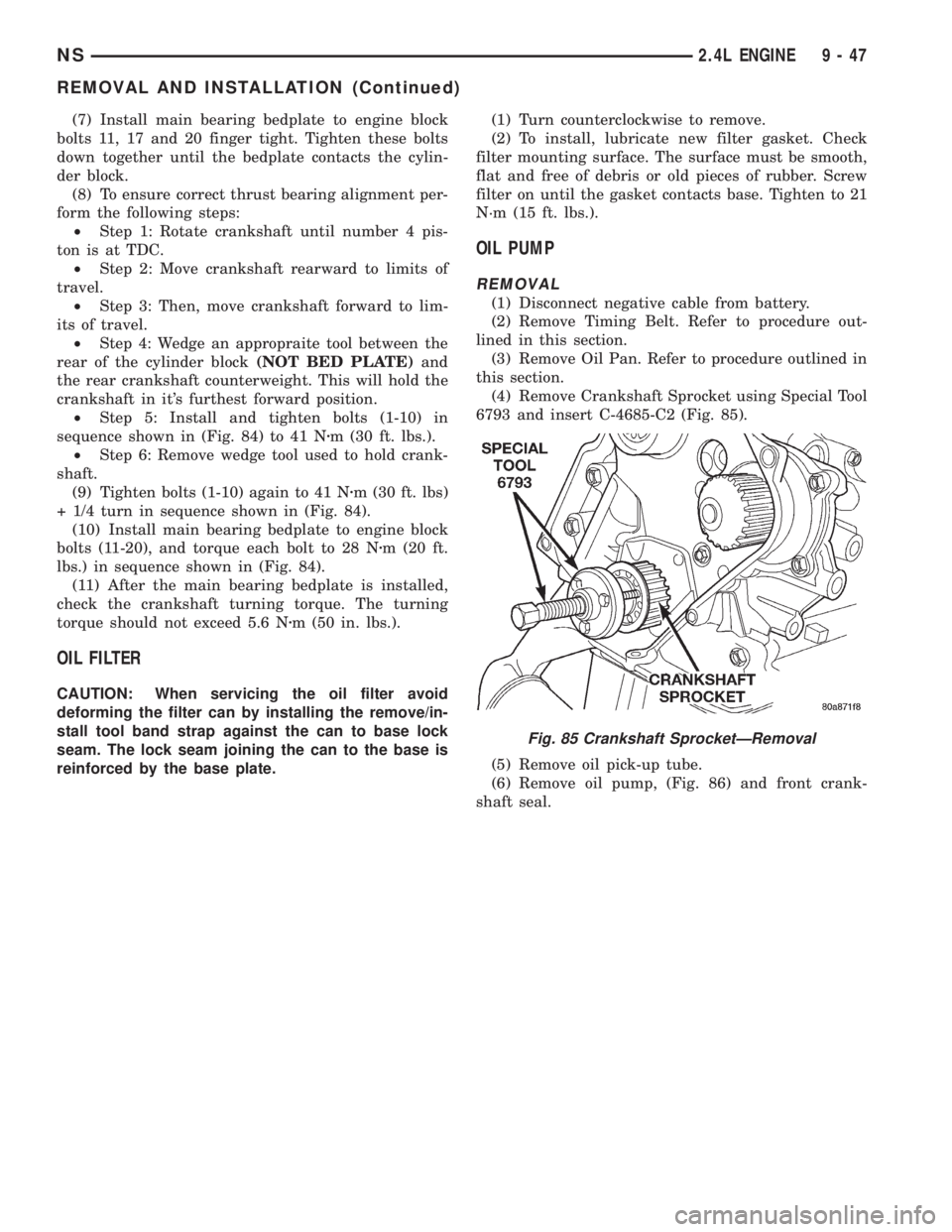
²Step 5: Install and tighten bolts (1-10) in
sequence shown in (Fig. 84) to 41 Nzm (30 ft. lbs.).
²Step 6: Remove wedge tool used to hold crank-
shaft.
(9) Tighten bolts (1-10) again to 41 Nzm (30 ft. lbs)
+ 1/4 turn in sequence shown in (Fig. 84).
(10) Install main bearing bedplate to engine block
bolts (11-20), and torque each bolt to 28 Nzm (20 ft.
lbs.) in sequence shown in (Fig. 84).
(11) After the main bearing bedplate is installed,
check the crankshaft turning torque. The turning
torque should not exceed 5.6 Nzm (50 in. lbs.).
OIL FILTER
CAUTION: When servicing the oil filter avoid
deforming the filter can by installing the remove/in-
stall tool band strap against the can to base lock
seam. The lock seam joining the can to the base is
reinforced by the base plate.(1) Turn counterclockwise to remove.
(2) To install, lubricate new filter gasket. Check
filter mounting surface. The surface must be smooth,
flat and free of debris or old pieces of rubber. Screw
filter on until the gasket contacts base. Tighten to 21
N´m (15 ft. lbs.).
OIL PUMP
REMOVAL
(1) Disconnect negative cable from battery.
(2) Remove Timing Belt. Refer to procedure out-
lined in this section.
(3) Remove Oil Pan. Refer to procedure outlined in
this section.
(4) Remove Crankshaft Sprocket using Special Tool
6793 and insert C-4685-C2 (Fig. 85).
(5) Remove oil pick-up tube.
(6) Remove oil pump, (Fig. 86) and front crank-
shaft seal.
Fig. 85 Crankshaft SprocketÐRemoval
NS2.4L ENGINE 9 - 47
REMOVAL AND INSTALLATION (Continued)