1996 CHRYSLER VOYAGER air condition
[x] Cancel search: air conditionPage 1433 of 1938
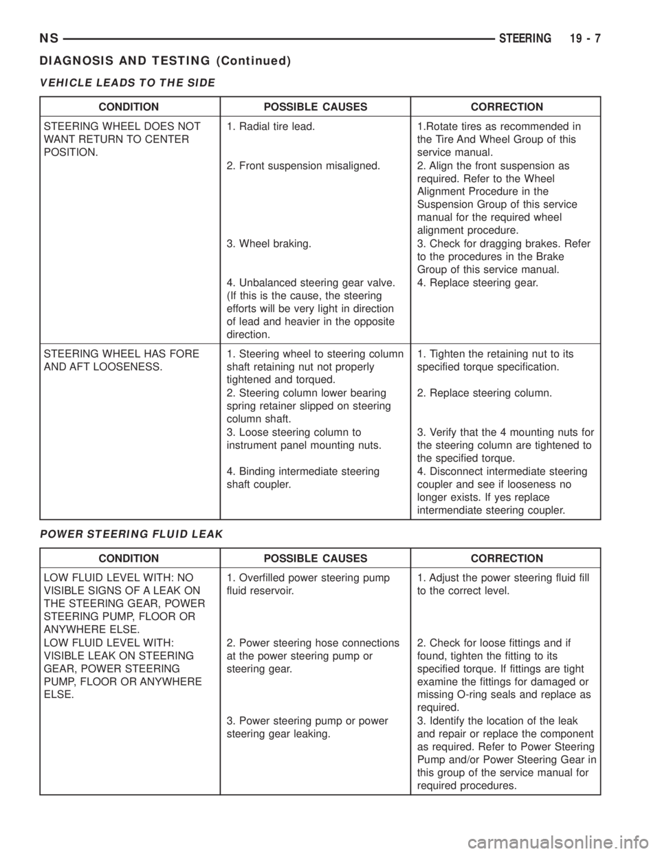
VEHICLE LEADS TO THE SIDE
POWER STEERING FLUID LEAK
CONDITION POSSIBLE CAUSES CORRECTION
STEERING WHEEL DOES NOT
WANT RETURN TO CENTER
POSITION.1. Radial tire lead. 1.Rotate tires as recommended in
the Tire And Wheel Group of this
service manual.
2. Front suspension misaligned. 2. Align the front suspension as
required. Refer to the Wheel
Alignment Procedure in the
Suspension Group of this service
manual for the required wheel
alignment procedure.
3. Wheel braking. 3. Check for dragging brakes. Refer
to the procedures in the Brake
Group of this service manual.
4. Unbalanced steering gear valve.
(If this is the cause, the steering
efforts will be very light in direction
of lead and heavier in the opposite
direction.4. Replace steering gear.
STEERING WHEEL HAS FORE
AND AFT LOOSENESS.1. Steering wheel to steering column
shaft retaining nut not properly
tightened and torqued.1. Tighten the retaining nut to its
specified torque specification.
2. Steering column lower bearing
spring retainer slipped on steering
column shaft.2. Replace steering column.
3. Loose steering column to
instrument panel mounting nuts.3. Verify that the 4 mounting nuts for
the steering column are tightened to
the specified torque.
4. Binding intermediate steering
shaft coupler.4. Disconnect intermediate steering
coupler and see if looseness no
longer exists. If yes replace
intermendiate steering coupler.
CONDITION POSSIBLE CAUSES CORRECTION
LOW FLUID LEVEL WITH: NO
VISIBLE SIGNS OF A LEAK ON
THE STEERING GEAR, POWER
STEERING PUMP, FLOOR OR
ANYWHERE ELSE.1. Overfilled power steering pump
fluid reservoir.1. Adjust the power steering fluid fill
to the correct level.
LOW FLUID LEVEL WITH:
VISIBLE LEAK ON STEERING
GEAR, POWER STEERING
PUMP, FLOOR OR ANYWHERE
ELSE.2. Power steering hose connections
at the power steering pump or
steering gear.2. Check for loose fittings and if
found, tighten the fitting to its
specified torque. If fittings are tight
examine the fittings for damaged or
missing O-ring seals and replace as
required.
3. Power steering pump or power
steering gear leaking.3. Identify the location of the leak
and repair or replace the component
as required. Refer to Power Steering
Pump and/or Power Steering Gear in
this group of the service manual for
required procedures.
NSSTEERING 19 - 7
DIAGNOSIS AND TESTING (Continued)
Page 1434 of 1938
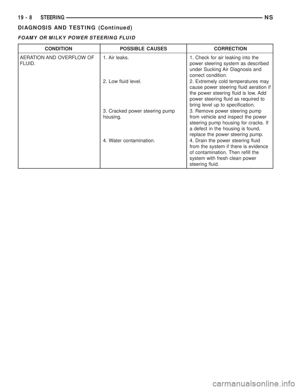
FOAMY OR MILKY POWER STEERING FLUID
CONDITION POSSIBLE CAUSES CORRECTION
AERATION AND OVERFLOW OF
FLUID.1. Air leaks. 1. Check for air leaking into the
power steering system as described
under Sucking Air Diagnosis and
correct condition.
2. Low fluid level. 2. Extremely cold temperatures may
cause power steering fluid aeration if
the power steering fluid is low. Add
power steering fluid as required to
bring level up to specification.
3. Cracked power steering pump
housing.3. Remove power steering pump
from vehicle and inspect the power
steering pump housing for cracks. If
a defect in the housing is found,
replace the power steering pump.
4. Water contamination. 4. Drain the power steering fluid
from the system if there is evidence
of contamination. Then refill the
system with fresh clean power
steering fluid.
19 - 8 STEERINGNS
DIAGNOSIS AND TESTING (Continued)
Page 1453 of 1938
The drive tangs on the pinion mate loosely with a
stub shaft to permit manual steering control to be
maintained if the drive belt on the power steering
pump should break. However, under these conditions,
steering effort will be increased.
DIAGNOSIS AND TESTING
POWER STEERING GEAR
The following procedure can be used to test the
operation of the power steering system on this vehi-
cle. This test will provide the flow rate for the power
steering system along with the maximum relief pres-
sure of the power steering pump. This test is to be
performed any time a power steering system problem
is present to determine if the power steering pump or
power steering gear is not functioning properly. The
following pressure and flow test is performed using
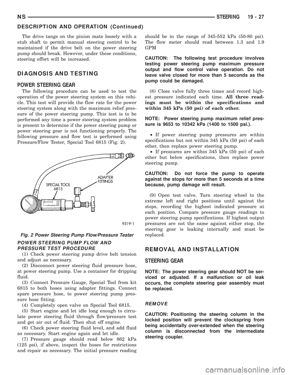
Pressure/Flow Tester, Special Tool 6815 (Fig. 2).
POWER STEERING PUMP FLOW AND
PRESSURE TEST PROCEDURE
(1) Check power steering pump drive belt tension
and adjust as necessary.
(2) Disconnect power steering fluid pressure hose,
at power steering pump. Use a container for dripping
fluid.
(3) Connect Pressure Gauge, Special Tool from kit
6815 to both hoses using adapter fittings. Connect
spare pressure hose, to power steering pump pres-
sure hose fitting.
(4) Completely open valve on Special Tool 6815.
(5) Start engine and let idle long enough to circu-
late power steering fluid through flow/pressure test
and get air out of fluid. Then shut off engine.
(6) Check power steering fluid level, and add fluid
as necessary. Start engine again and let idle.
(7) Pressure gauge should read below 862 kPa
(125 psi), if above, inspect the hoses for restrictions
and repair as necessary. The initial pressure readingshould be in the range of 345-552 kPa (50-80 psi).
The flow meter should read between 1.3 and 1.9
GPM
CAUTION: The following test procedure involves
testing power steering pump maximum pressure
output and flow control valve operation. Do not
leave valve closed for more than 5 seconds as the
pump could be damaged.
(8) Close valve fully three times and record high-
est pressure indicated each time.All three read-
ings must be within the specifications and
within 345 kPa (50 psi) of each other.
NOTE: Power steering pump maximum relief pres-
sure is 9653 to 10342 kPa (1400 to 1500 psi.).
²If power steering pump pressures are within
specifications but not within 345 kPa (50 psi) of each
other, then replace power steering pump.
²If pressures are within 345 kPa (50 psi) of each
other but below specifications, then replace power
steering pump.
CAUTION: Do not force the pump to operate
against the stops for more than 5 seconds at a time
because, pump damage will result.
(9) Open test valve. Turn steering wheel to the
extreme left and right positions until against the
stops, recording the highest indicated pressure at
each position. Compare pressure gauge readings to
power steering pump specifications. If highest output
pressures are not the same against either stop, the
steering gear is leaking internally and must be
replaced.REMOVAL AND INSTALLATION
STEERING GEAR
NOTE: The power steering gear should NOT be ser-
viced or adjusted. If a malfunction or oil leak
occurs, the complete steering gear assembly must
be replaced.
REMOVE
CAUTION: Positioning the steering column in the
locked position will prevent the clockspring from
being accidentally over-extended when the steering
column is disconnected from the intermediate
steering coupler.
Fig. 2 Power Steering Pump Flow/Pressure Tester
NSSTEERING 19 - 27
DESCRIPTION AND OPERATION (Continued)
Page 1464 of 1938
DIAGNOSIS AND TESTING
STEERING COLUMN
For diagnosis of conditions relating to the steering
column, refer to the steering system diagnosis charts,
in the diagnosis and testing section at the beginning
of this group.
SERVICE PROCEDURES
STEERING COLUMN SERVICE PROCEDURE
WARNINGS
WARNING: BEFORE BEGINNING ANY SERVICE
PROCEDURES THAT INVOLVES REMOVING THE
AIR BAG. REMOVE AND ISOLATE THE NEGATIVE
(-) BATTERY CABLE (GROUND) FROM THE VEHI-
CLE BATTERY. THIS IS THE ONLY SURE WAY TO
DISABLE THE AIR BAG SYSTEM. FAILURE TO DO
THIS COULD RESULT IN ACCIDENTAL AIR BAG
DEPLOYMENT AND POSSIBLE PERSONAL INJURY.
WARNING: THE AIR BAG SYSTEM IS A SENSITIVE,
COMPLEX ELECTRO-MECHANICAL UNIT. BEFORE
ATTEMPTING TO DIAGNOSE, REMOVE OR INSTALL
THE AIR BAG SYSTEM COMPONENTS YOU MUST
FIRST DISCONNECT AND ISOLATE THE BATTERY
NEGATIVE (GROUND) CABLE. FAILURE TO DO SO
COULD RESULT IN ACCIDENTAL DEPLOYMENT OF
THE AIR BAG AND POSSIBLE PERSONAL INJURY.
THE FASTENERS, SCREWS, AND BOLTS, ORIGI-
NALLY USED FOR THE AIR BAG COMPONENTS,
HAVE SPECIAL COATINGS AND ARE SPECIFI-
CALLY DESIGNED FOR THE AIR BAG SYSTEM.
THEY MUST NEVER BE REPLACED WITH ANY SUB-
STITUTES. ANYTIME A NEW FASTENER IS
NEEDED, REPLACE WITH THE CORRECT FASTEN-
ERS PROVIDED IN THE SERVICE PACKAGE OR
FASTENERS LISTED IN THE PARTS BOOKS.
BEFORE SERVICING A STEERING COLUMN
EQUIPPED WITH AN AIR BAG, REFER TO GROUP
8M, ELECTRICAL FOR PROPER AND SAFE SER-
VICE PROCEDURES.
NOTE: Safety goggles should be worn at all times
when working on steering columns.
CAUTION: Disconnect negative (ground) cable
from the battery, before servicing any column com-
ponent.CAUTION: Do not attempt to remove the pivot pins
to disassemble the tilting mechanism. Damage will
occur.
REMOVAL AND INSTALLATION
STEERING COLUMN ASSEMBLY
To service the steering wheel and its components
or the air bag, refer to Group 8M, Restraint Systems.
Follow all WARNINGS.
To service the switches, refer to the appropriate
section of Group 8, Electrical.
To replace the steering column assembly, refer to
the steering column removal procedure.
REMOVE
(1) Make sure the front wheels of the vehicle are
in thestraight aheadposition before beginning the
column removal procedure.
(2) Disconnect negative (ground) cable from the
battery and isolate cable from battery terminal.
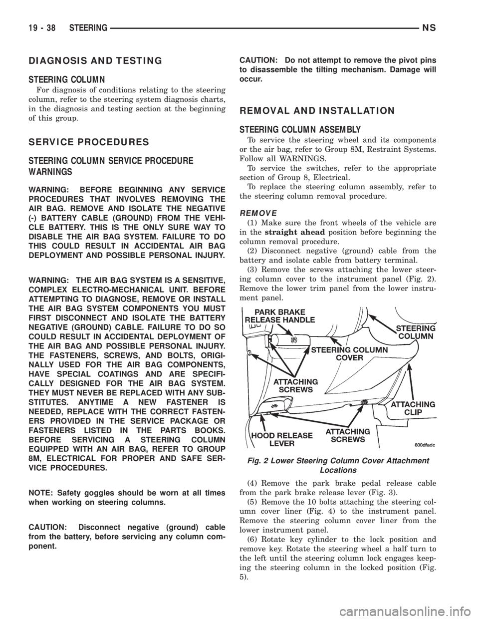
(3) Remove the screws attaching the lower steer-
ing column cover to the instrument panel (Fig. 2).
Remove the lower trim panel from the lower instru-
ment panel.
(4) Remove the park brake pedal release cable
from the park brake release lever (Fig. 3).
(5) Remove the 10 bolts attaching the steering col-
umn cover liner (Fig. 4) to the instrument panel.
Remove the steering column cover liner from the
lower instrument panel.
(6) Rotate key cylinder to the lock position and
remove key. Rotate the steering wheel a half turn to
the left until the steering column lock engages keep-
ing the steering column in the locked position (Fig.
5).
Fig. 2 Lower Steering Column Cover Attachment
Locations
19 - 38 STEERINGNS
Page 1470 of 1938
CAUTION: Before installing the steering wheel the
clockspring must be centered. If clockspring is not
centered, the wiring in the clockspring may be over-
extended and break when the steering wheel is
rotated. Use the following procedure to center the
clockspring.
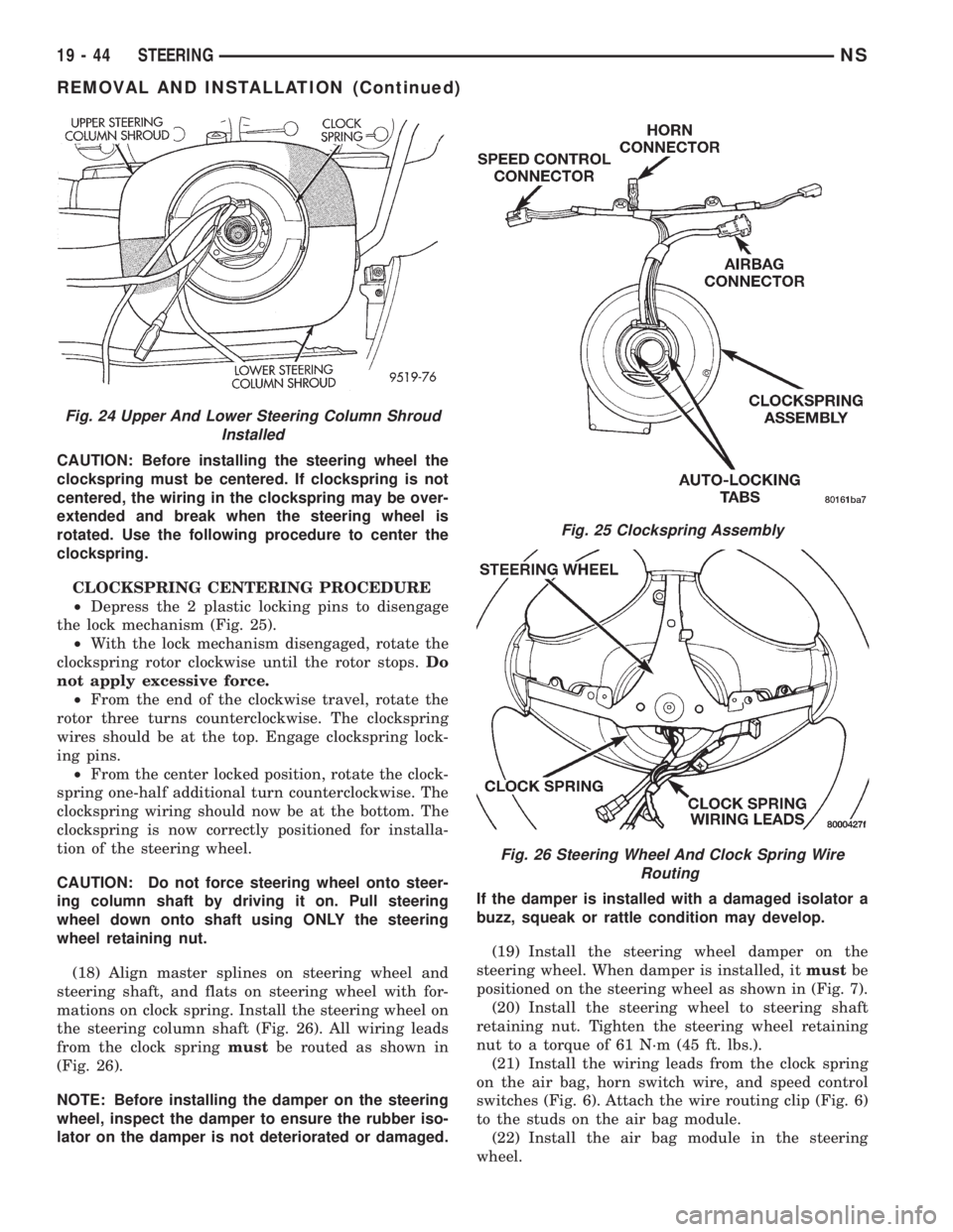
CLOCKSPRING CENTERING PROCEDURE
²Depress the 2 plastic locking pins to disengage
the lock mechanism (Fig. 25).
²With the lock mechanism disengaged, rotate the
clockspring rotor clockwise until the rotor stops.Do
not apply excessive force.
²From the end of the clockwise travel, rotate the
rotor three turns counterclockwise. The clockspring
wires should be at the top. Engage clockspring lock-
ing pins.
²From the center locked position, rotate the clock-
spring one-half additional turn counterclockwise. The
clockspring wiring should now be at the bottom. The
clockspring is now correctly positioned for installa-
tion of the steering wheel.
CAUTION: Do not force steering wheel onto steer-
ing column shaft by driving it on. Pull steering
wheel down onto shaft using ONLY the steering
wheel retaining nut.
(18) Align master splines on steering wheel and
steering shaft, and flats on steering wheel with for-
mations on clock spring. Install the steering wheel on
the steering column shaft (Fig. 26). All wiring leads
from the clock springmustbe routed as shown in
(Fig. 26).
NOTE: Before installing the damper on the steering
wheel, inspect the damper to ensure the rubber iso-
lator on the damper is not deteriorated or damaged.If the damper is installed with a damaged isolator a
buzz, squeak or rattle condition may develop.
(19) Install the steering wheel damper on the
steering wheel. When damper is installed, itmustbe
positioned on the steering wheel as shown in (Fig. 7).
(20) Install the steering wheel to steering shaft
retaining nut. Tighten the steering wheel retaining
nut to a torque of 61 N´m (45 ft. lbs.).
(21) Install the wiring leads from the clock spring
on the air bag, horn switch wire, and speed control
switches (Fig. 6). Attach the wire routing clip (Fig. 6)
to the studs on the air bag module.
(22) Install the air bag module in the steering
wheel.
Fig. 24 Upper And Lower Steering Column Shroud
Installed
Fig. 25 Clockspring Assembly
Fig. 26 Steering Wheel And Clock Spring Wire
Routing
19 - 44 STEERINGNS
REMOVAL AND INSTALLATION (Continued)
Page 1475 of 1938
TRANSAXLE AND POWER TRANSFER UNIT
CONTENTS
page page
31TH AUTOMATIC TRANSAXLE.............. 1
41TE AUTOMATIC TRANSAXLE............. 71POWER TRANSFER UNIT................. 165
31TH AUTOMATIC TRANSAXLE
INDEX
page page
GENERAL INFORMATION
31TH TRANSAXLE........................ 2
FLUID LEVEL AND CONDITION.............. 2
SELECTION OF LUBRICANT................ 3
SPECIAL ADDITIVES...................... 3
DESCRIPTION AND OPERATION
CLUTCHES, BAND SERVOS, AND
ACCUMULATOR
...................... 3
FLOW CONTROL VALVES.................. 3
GEARSHIFT AND PARKING LOCK CONTROLS . . 4
GOVERNOR............................. 4
HYDRAULIC CONTROL SYSTEM............. 3
PRESSURE REGULATING VALVES........... 3
PRESSURE SUPPLY SYSTEM............... 3
TORQUE CONVERTER CLUTCH SOLENOID
WIRING CONNECTOR................... 4
TORQUE CONVERTER CLUTCH............. 3
DIAGNOSIS AND TESTING
CLUTCH AND SERVO AIR PRESSURE TESTS . 15
FLUID LEAKAGE-TRANSAXLE TORQUE
CONVERTER HOUSING AREA............ 15
HYDRAULIC PRESSURE TESTS............ 13
ROAD TEST............................. 4
THREE SPEED TRANSAXLE DIAGNOSIS AND
TESTS............................... 4
SERVICE PROCEDURES
ALUMINUM THREAD REPAIR.............. 18
FLUID AND FILTER CHANGE............... 16
FLUID DRAIN AND REFILL................. 18
FLUSHING COOLERS AND TUBES.......... 18
OIL PUMP VOLUME CHECK............... 19
REMOVAL AND INSTALLATION
FRONT PUMP OIL SEAL.................. 21
PARK/NEUTRAL STARTING AND BACK-UP
LAMP SWITCH........................ 19
TRANSAXLE AND TORQUE CONVERTER
REMOVAL............................ 20
VEHICLE SPEED SENSOR PINION GEAR..... 19DISASSEMBLY AND ASSEMBLY
ACCUMULATOR-RECONDITION............ 36
DIFFERENTIAL REPAIR................... 46
FRONT CLUTCH-RECONDITION............ 32
FRONT PLANETARY & ANNULUS GEAR-
RECONDITION........................ 35
KICKDOWN SERVO (CONTROLLED LOAD)-
RECONDITION........................ 37
LOW/REVERSE (REAR)
SERVO-RECONDITION.................. 36
OIL PUMP-RECONDITION................. 31
OUTPUT SHAFT REPAIR.................. 43
PARKING PAWL......................... 42
REAR CLUTCH-RECONDITION............. 33
TRANSAXLE........................... 21
TRANSFER SHAFT REPAIR................ 38
VALVE BODY RECONDITION............... 27
CLEANING AND INSPECTION
VALVE BODY........................... 50
ADJUSTMENTS
BAND ADJUSTMENT..................... 51
BEARING ADJUSTMENT PROCEDURES...... 52
DIFFERENTIAL BEARING................. 53
GEARSHIFT CABLE ADJUSTMENT.......... 51
HYDRAULIC CONTROL PRESSURE
ADJUSTMENTS....................... 52
OUTPUT SHAFT BEARING................ 52
THROTTLE PRESSURE LINKAGE
ADJUSTMENT......................... 51
TRANSFER SHAFT BEARING.............. 54
SCHEMATICS AND DIAGRAMS
31TH TRANSAXLE HYDRAULIC SCHEMATIC . . 56
SPECIFICATIONS
31TH AUTOMATIC TRANSAXLE............. 64
31TH TORQUE SPECIFICATIONS........... 65
SPECIAL TOOLS
31TH AUTOMATIC TRANSAXLE............. 66
NSTRANSAXLE AND POWER TRANSFER UNIT 21 - 1
Page 1476 of 1938
GENERAL INFORMATION
31TH TRANSAXLE
NOTE: Safety goggles should be worn at all times
when working on these transaxles.
This transaxle combines torque converter, three
speed transmission, final drive gearing, and differen-
tial into a front wheel drive system. The identifica-
tion markings and usage of the transaxle are charted
in Diagnosis and Tests.
NOTE: Transaxle operation requirements are differ-
ent for each vehicle and engine combination. Some
internal parts will be different to provide for this.
Therefore, when replacing parts, refer to the seven
digit part number stamped on rear of the transaxle
oil pan flange.
Within this transaxle, there are three primary
areas:
(1) Main center line plus valve body.
(2) Transfer shaft center line (includes governor
and parking sprag).
(3) Differential center line.
(4) Center distances between the main rotating
parts in these three areas are held precise to main-
tain a low noise level.
(5) The torque converter, transaxle area, and dif-
ferential are housed in an integral aluminum die
casting.The differential oil sump is common
with the transaxle sump. Separate filling of the
differential is NOT necessary.
(6) The torque converter is attached to the crank-
shaft through a flexible driving plate. Cooling of the
converter is accomplished by circulating the tran-
saxle fluid through a remote cooler. There are two
types of coolers used. An oil-to-water type cooler
located in the radiator side tank and/or an oil-to air
heat exchanger. The torque converter assembly is a
sealed unit that cannot be disassembled.
(7) The transaxle fluid is filtered by an internal fil-
ter attached to the lower side of the valve body
assembly.
(8) Engine torque is transmitted to the torque con-
verter then, through the input shaft to multiple-disc
clutches in the transaxle. The power flow depends on
the application of the clutches and bands. Refer to
Elements in Use Chart in Diagnosis and Tests sec-
tion.
(9) The transaxle consists of:
²Two multiple-disc clutches
²An overrunning clutch
²Two servos
²A hydraulic accumulator
²Two bands²Two planetary gear sets
This provides three forward ratios and a reverse
ratio. The common sun gear of the planetary gear
sets is connected to the front clutch by a driving
shell. The drive shell is splined to the sun gear and
front clutch retainer. The hydraulic system consists
of an oil pump, and a single valve body which con-
tains all of the valves except the governor valves.
The transaxle sump and differential sump are both
vented through the dipstick. Output torque from the
main center line is delivered through helical gears to
the transfer shaft. This gear set is a factor of the
final drive (axle) ratio. The shaft also carries the gov-
ernor and parking sprag. An integral helical gear on
the transfer shaft drives the differential ring gear.
The final drive gearing is completed with one of two
gear ratios of 2.98 or 3.19 depending on model and
application.
FLUID LEVEL AND CONDITION
NOTE: The transmission and differential sump have
a common oil sump with a communicating opening
between the two.
The torque converter fills in both the P Park and N
Neutral positions. Place the selector lever in P Park
to be sure that the fluid level check is accurate.The
engine should be running at idle speed for at
least one minute, with the vehicle on level
ground. This will assure complete oil level sta-
bilization between differential and transmis-
sion.The fluid should be at normal operating
temperature (approximately 82 C. or 180 F.). The
fluid level is correct if it is in the HOT region (cross-
hatched area) on the dipstick.
Low fluid level can cause a variety of conditions
because it allows the pump to take in air along with
the fluid. As in any hydraulic system, air bubbles
make the fluid spongy, therefore, pressures will be
low and build up slowly.
Improper filling can also raise the fluid level too
high. When the transaxle has too much fluid, the
gears churn up foam and cause the same conditions
which occur with a low fluid level.
In either case, the air bubbles can cause overheat-
ing, fluid oxidation, and varnishing. This can inter-
fere with normal valve, clutch, and servo operation.
Foaming can also result in fluid escaping from the
transaxle dipstick where it may be mistaken for a
leak.
Along with fluid level, it is important to check the
condition of the fluid. When the fluid smells burned,
and is contaminated with metal or friction material
particles, a complete transaxle overhaul is needed.
Be sure to examine the fluid on the dipstick closely.
21 - 2 TRANSAXLE AND POWER TRANSFER UNITNS
Page 1489 of 1938
(4) Low pressure in R and 1 but correct pressure
in 2 indicates rear servo circuit leakage.
(5) Low line pressure in all positions indicates a
defective pump, a clogged filter, or a stuck pressure
regulator valve.
GOVERNOR PRESSURE
Test only if transaxle shifts at wrong vehicle
speeds when throttle cable is correctly adjusted.
(1) Connect a 0-150 psi pressure gauge to governor
pressure take-off point. It is located at lower right
side of case, below differential cover.
(2) Operate transaxle in third gear to read pres-
sures. The governor pressure should respond
smoothly to changes in mph and should return to 0
to 3 psi when vehicle is stopped. High pressure at
standstill (above 3 psi) will prevent the transaxle
from downshifting.
THROTTLE PRESSURE
No gauge port is provided for throttle pressure.
Incorrect throttle pressure should be suspected if
part throttle upshift speeds are either delayed or
occur too early in relation to vehicle speeds. Engine
runaway on shifts can also be an indicator of low
throttle pressure setting, or misadjusted throttle
cable.
In no case should throttle pressure be adjusted
until the transaxle throttle cable adjustment has
been verified to be correct.
CLUTCH AND SERVO AIR PRESSURE TESTS
A no drive condition might exist even with correct
fluid pressure, because of inoperative clutches or
bands. The inoperative units, clutches, bands, and
servos can be located through a series of tests. This
is done by substituting air pressure for fluid pressure
(Fig. 4) .
The front and rear clutches, kickdown servo, and
low-reverse servo may be tested by applying air pres-
sure to their respective passages. To make air pres-
sure tests, proceed as follows:
NOTE: Compressed air supply must be free of all
dirt or moisture. Use a pressure of 30 psi.
Remove oil pan and valve body. Refer to Valve
Body for removal procedure.
FRONT CLUTCH
Apply air pressure to front clutch apply passage
and listen for a dull thud which indicates that front
clutch is operating. Hold air pressure on for a few
seconds and inspect system for excessive oil leaks.
REAR CLUTCH
Apply air pressure to rear clutch apply passage
and listen for a dull thud which indicates that rear
clutch is operating. Also inspect for excessive oil
leaks. If a dull thud cannot be heard in the clutches,
place finger tips on clutch housing and again apply
air pressure. Movement of piston can be felt as the
clutch is applied.
KICKDOWN SERVO (FRONT)
Direct air pressure into KICKDOWN SERVO ON
passage. Operation of servo is indicated by a tighten-
ing of front band. Spring tension on servo piston
should release the band.
LOW AND REVERSE SERVO (REAR)
Direct air pressure into LOW-REVERSE SERVO
APPLY passage. Operation of servo is indicated by a
tightening of rear band. Spring tension on servo pis-
ton should release the band.
If clutches and servos operate properly, no upshift
indicates that a malfunction exists in the valve body.
FLUID LEAKAGE-TRANSAXLE TORQUE
CONVERTER HOUSING AREA
(1) Check for source of leakage.
(2) Since fluid leakage near the torque converter
area may be from an engine oil leak, the area should
be checked closely. Factory fill fluid is dyed red and,
therefore, can be distinguished from engine oil.
(3) Prior to removing the transaxle, perform the
following checks:
(4) When leakage is determined to originate from
the transaxle, check fluid level prior to removal of
the transaxle and torque converter.
(5) High oil level can result in oil leakage out the
vent in the dipstick. If the fluid level is high, adjust
to proper level.
(6) After performing this operation, inspect for
leakage. If a leak persists, perform the following
operation on the vehicle. This will determine if the
torque converter or transaxle is leaking.
TORQUE CONVERTER LEAKAGE
Possible sources of torque converter leakage are:
²Torque converter weld leaks at the outside diam-
eter (peripheral) weld.
²Torque converter hub weld.
²Torque converter impeller shell cracked adjacent
to hub.
²At drive lug welds.
NOTE: Hub weld is inside and not visible. Do not
attempt to repair. Replace torque converter.
NSTRANSAXLE AND POWER TRANSFER UNIT 21 - 15
DIAGNOSIS AND TESTING (Continued)