1996 CHRYSLER VOYAGER air condition
[x] Cancel search: air conditionPage 1222 of 1938
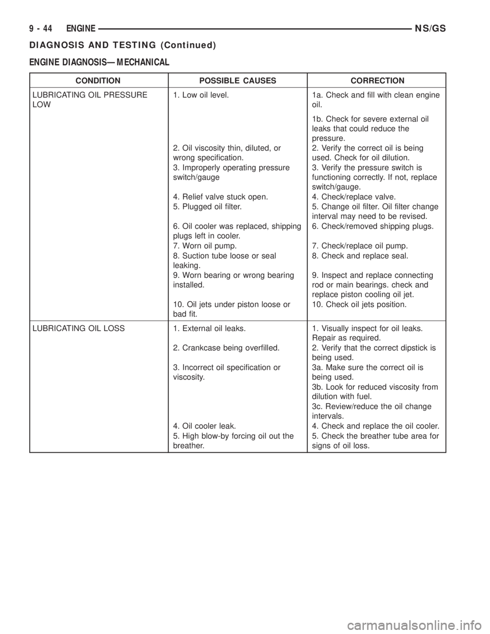
ENGINE DIAGNOSISÐMECHANICAL
CONDITION POSSIBLE CAUSES CORRECTION
LUBRICATING OIL PRESSURE
LOW1. Low oil level. 1a. Check and fill with clean engine
oil.
1b. Check for severe external oil
leaks that could reduce the
pressure.
2. Oil viscosity thin, diluted, or
wrong specification.2. Verify the correct oil is being
used. Check for oil dilution.
3. Improperly operating pressure
switch/gauge3. Verify the pressure switch is
functioning correctly. If not, replace
switch/gauge.
4. Relief valve stuck open. 4. Check/replace valve.
5. Plugged oil filter. 5. Change oil filter. Oil filter change
interval may need to be revised.
6. Oil cooler was replaced, shipping
plugs left in cooler.6. Check/removed shipping plugs.
7. Worn oil pump. 7. Check/replace oil pump.
8. Suction tube loose or seal
leaking.8. Check and replace seal.
9. Worn bearing or wrong bearing
installed.9. Inspect and replace connecting
rod or main bearings. check and
replace piston cooling oil jet.
10. Oil jets under piston loose or
bad fit.10. Check oil jets position.
LUBRICATING OIL LOSS 1. External oil leaks. 1. Visually inspect for oil leaks.
Repair as required.
2. Crankcase being overfilled. 2. Verify that the correct dipstick is
being used.
3. Incorrect oil specification or
viscosity.3a. Make sure the correct oil is
being used.
3b. Look for reduced viscosity from
dilution with fuel.
3c. Review/reduce the oil change
intervals.
4. Oil cooler leak. 4. Check and replace the oil cooler.
5. High blow-by forcing oil out the
breather.5. Check the breather tube area for
signs of oil loss.
9 - 44 ENGINENS/GS
DIAGNOSIS AND TESTING (Continued)
Page 1223 of 1938
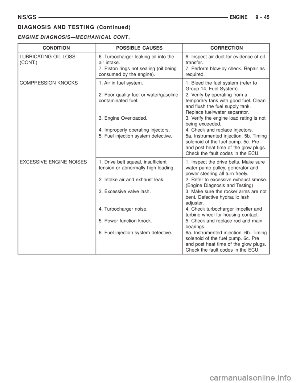
ENGINE DIAGNOSISÐMECHANICAL CONT.
CONDITION POSSIBLE CAUSES CORRECTION
LUBRICATING OIL LOSS
(CONT.)6. Turbocharger leaking oil into the
air intake.6. Inspect air duct for evidence of oil
transfer.
7. Piston rings not sealing (oil being
consumed by the engine).7. Perform blow-by check. Repair as
required.
COMPRESSION KNOCKS 1. Air in fuel system. 1. Bleed the fuel system (refer to
Group 14, Fuel System).
2. Poor quality fuel or water/gasoline
contaminated fuel.2. Verify by operating from a
temporary tank with good fuel. Clean
and flush the fuel supply tank.
Replace fuel/water separator.
3. Engine Overloaded. 3. Verify the engine load rating is not
being exceeded.
4. Improperly operating injectors. 4. Check and replace injectors.
5. Fuel injection system defective. 5a. Instrumented injection. 5b. Timing
solenoid of the fuel pump. 5c. Pre
and post heat time of the glow plugs.
Check the fault codes in the ECU.
EXCESSIVE ENGINE NOISES 1. Drive belt squeal, insufficient
tension or abnormally high loading.1. Inspect the drive belts. Make sure
water pump pulley, generator and
power steering all turn freely.
2. Intake air and exhaust leak. 2. Refer to excessive exhaust smoke.
(Engine Diagnosis and Testing)
3. Excessive valve lash. 3. Make sure the rocker arms are not
bent. Defective hydraulic lash
adjuster.
4. Turbocharger noise. 4. Check turbocharger impeller and
turbine wheel for housing contact.
5. Power function knock. 5. Check and replace rod and main
bearings.
6. Fuel injection system defective. 6a. Instrumented injection. 6b. Timing
solenoid of the fuel pump. 6c. Pre
and post heat time of the glow plugs.
Check the fault codes in the ECU.
NS/GSENGINE 9 - 45
DIAGNOSIS AND TESTING (Continued)
Page 1225 of 1938
HYDRAULIC TAPPETS
Before disassembling any part of the engine to cor-
rect tappet noise, check the oil pressure. If vehicle
has no oil pressure gauge, install a reliable gauge at
the pressure sending unit. The pressure should be
between 3.5 bars to 5.0 bars at 4000 RPM.
Check the oil level after the engine reaches normal
operating temperature. Allow 5 minutes to stabilize
oil level, check dipstick. The oil level in the pan
should never be above the FULL mark or below the
ADD OIL mark on dipstick. Either of these 2 condi-
tions could be responsible for noisy tappets.
OIL LEVEL HIGH
If oil level is above the FULL mark, it is possible
for the connecting rods to dip into the oil. With the
engine running, this condition could create foam in
the oil pan. Foam in oil pan would be fed to the
hydraulic tappets by the oil pump causing them to
lose length and allow valves to seat noisily.
OIL LEVEL LOW
Low oil level may allow oil pump to take in air.
When air is fed to the tappets, they lose length which
allows valves to seat noisily. Any leaks on intake side
of oil pump through which air can be drawn will cre-
ate the same tappet action. Check the lubrication
system from the intake strainer to the pump cover,
including the relief valve retainer cap. When tappet
noise is due to aeration, it may be intermittent or
constant, and usually more than 1 tappet will be
noisy. When oil level and leaks have been corrected,
operate the engine at fast idle. Run engine for a suf-
ficient time to allow all of the air inside the tappets
to be bled out.
TAPPET NOISE DIAGNOSIS
(1) To determine source of tappet noise, operate
engine at idle with cylinder head covers removed.
(2) Feel each valve spring or rocker arm to detect
noisy tappet. The noisy tappet will cause the affected
spring and/or rocker arm to vibrate or feel rough in
operation.
NOTE: Worn valve guides or cocked springs are
sometimes mistaken for noisy tappets. If such is
the case, noise may be dampened by applying side
thrust on the valve spring. If noise is not apprecia-
bly reduced, it can be assumed the noise is in the
tappet. Inspect the rocker arm push rod sockets
and push rod ends for wear.
(3) Valve tappet noise ranges from light noise to a
heavy click. A light noise is usually caused by exces-
sive leak down around the unit plunger or by the
plunger partially sticking in the tappet body cylinder.
The tappet should be replaced. A heavy click iscaused by a tappet check valve not seating or by for-
eign particles becoming wedged between the plunger
and the tappet body. This will cause the plunger to
stick in the down position. This heavy click will be
accompanied by excessive clearance between the
valve stem and rocker arm as valve closes. In either
case, tappet assembly should be removed for inspec-
tion and cleaning.
(4) The valve train generates a noise very much
like a light tappet noise during normal operation.
Care must be taken to ensure that tappets are mak-
ing the noise. In general, if more than one tappet
seems to be noisy, its probably not the tappets.
SERVICE PROCEDURES
CHECKING OIL LEVEL
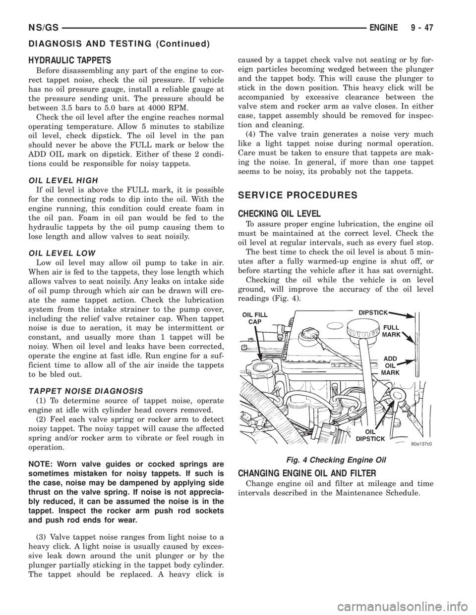
To assure proper engine lubrication, the engine oil
must be maintained at the correct level. Check the
oil level at regular intervals, such as every fuel stop.
The best time to check the oil level is about 5 min-
utes after a fully warmed-up engine is shut off, or
before starting the vehicle after it has sat overnight.
Checking the oil while the vehicle is on level
ground, will improve the accuracy of the oil level
readings (Fig. 4).
CHANGING ENGINE OIL AND FILTER
Change engine oil and filter at mileage and time
intervals described in the Maintenance Schedule.
Fig. 4 Checking Engine Oil
NS/GSENGINE 9 - 47
DIAGNOSIS AND TESTING (Continued)
Page 1233 of 1938
(3) Install cylinder head cover, torque nuts to 14.7
N´m (132 in. lbs.).
(4) Install coolant pressure tank.
(5) Install breather hose.
(6) Install generator bracket, tighten bolts to 7
N´m (4 ft. lbs.).
(7) Connect the service valves to the A/C compres-
sor ports, if equipped with air conditioning.
(8) Connect battery cable.
VALVE SPRINGSÐCYLINDER HEAD NOT
REMOVED
This procedure can be done with the engine cylin-
der head installed on the block.
REMOVAL
Each valve spring is held in place by a retainer
and a set of conical valve locks. The locks can be
removed only by compressing the valve spring.
(1) Remove the engine cylinder head cover, refer to
cylinder head cover removal in this section.
(2) Remove rocker arms assemblies for access to
each valve spring to be removed.
(3) Remove push rods. Retain the push rods, and
rocker arms assemblies in the same order and posi-
tion as removed.
(4) Inspect the springs and retainer for cracks and
possible signs of weakening.
(5) Install an air hose adaptor in the fuel injector
hole.
(6) Connect an air hose to the adapter and apply
air pressure slowly. Maintain at least 621 kPa (90psi) of air pressure in the cylinder to hold the valves
against their seats.
(7) Tap the retainer or tip with a rawhide hammer
to loosen the lock from the retainer. Use Valve Spring
Compressor Tool to compress the spring and remove
the locks.
(8) Remove valve spring and retainer.
Inspect the valve stems, especially the grooves. An
Arkansas smooth stone should be used to remove
nicks and high spots.
INSTALLATION
(1) Install valve spring and retainer.
(2) Compress the valve spring with Valve Spring
Compressor Tool and insert the valve locks. Release
the spring tension and remove the tool. Tap the
spring from side-to-side to ensure that the spring is
seated properly on the engine cylinder head.
(3) Disconnect the air hose. Remove the adaptor
from the fuel injector hole and install the fuel injec-
tor.
(4) Repeat the procedures for each remaining valve
spring to be removed.
(5) Install the push rods. Ensure the bottom end of
each rod is centered in the plunger cap seat of the
hydraulic valve tappet.
(6) Install the rocker arm assemblies, at their orig-
inal location.
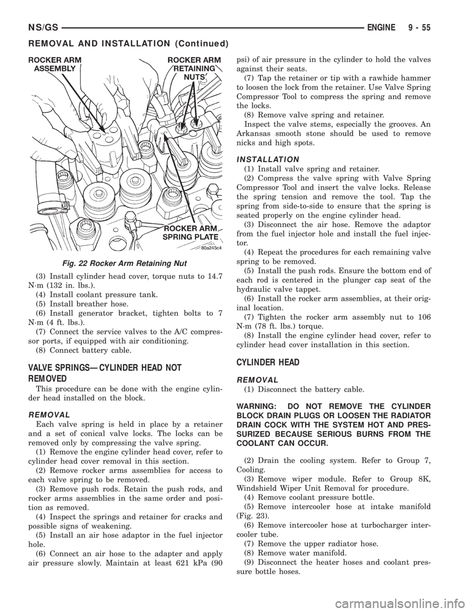
(7) Tighten the rocker arm assembly nut to 106
N´m (78 ft. lbs.) torque.
(8) Install the engine cylinder head cover, refer to
cylinder head cover installation in this section.
CYLINDER HEAD
REMOVAL
(1) Disconnect the battery cable.
WARNING: DO NOT REMOVE THE CYLINDER
BLOCK DRAIN PLUGS OR LOOSEN THE RADIATOR
DRAIN COCK WITH THE SYSTEM HOT AND PRES-
SURIZED BECAUSE SERIOUS BURNS FROM THE
COOLANT CAN OCCUR.
(2) Drain the cooling system. Refer to Group 7,
Cooling.
(3) Remove wiper module. Refer to Group 8K,
Windshield Wiper Unit Removal for procedure.
(4) Remove coolant pressure bottle.
(5) Remove intercooler hose at intake manifold
(Fig. 23).
(6) Remove intercooler hose at turbocharger inter-
cooler tube.
(7) Remove the upper radiator hose.
(8) Remove water manifold.
(9) Disconnect the heater hoses and coolant pres-
sure bottle hoses.
Fig. 22 Rocker Arm Retaining Nut
NS/GSENGINE 9 - 55
REMOVAL AND INSTALLATION (Continued)
Page 1240 of 1938
(7) Remove power steering/air conditioning pulley
nut. Remove pulley.
CAUTION: Remove old loctite from threads on
pump.
(8) Remove pump shaft support bracket assembly.
(9) Disconnect the water drain pipe hose at the
timing cover.
CAUTION: When separating the timing geat cover
from the block take care not to damage the mating
surface of the timing gear cover or block. Also take
care not to damage the timing gears or components
located inside the timing gear cover near the edge.
(10) Remove timing gear cover.
INSTALLATION
(1) Apply a continuous 3 mm bead of Silicone
Sealer to timing cover, install within 10 minutes,
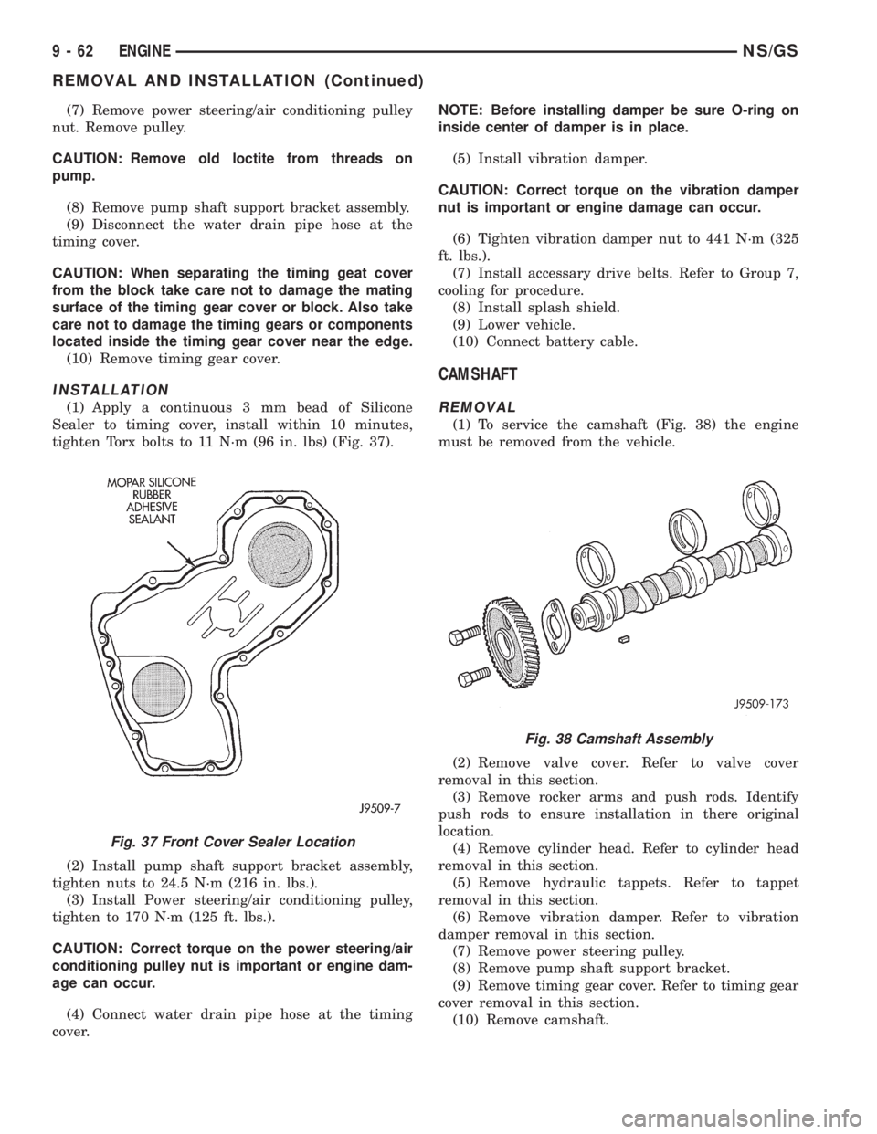
tighten Torx bolts to 11 N´m (96 in. lbs) (Fig. 37).
(2) Install pump shaft support bracket assembly,
tighten nuts to 24.5 N´m (216 in. lbs.).
(3) Install Power steering/air conditioning pulley,
tighten to 170 N´m (125 ft. lbs.).
CAUTION: Correct torque on the power steering/air
conditioning pulley nut is important or engine dam-
age can occur.
(4) Connect water drain pipe hose at the timing
cover.NOTE: Before installing damper be sure O-ring on
inside center of damper is in place.
(5) Install vibration damper.
CAUTION: Correct torque on the vibration damper
nut is important or engine damage can occur.
(6) Tighten vibration damper nut to 441 N´m (325
ft. lbs.).
(7) Install accessary drive belts. Refer to Group 7,
cooling for procedure.
(8) Install splash shield.
(9) Lower vehicle.
(10) Connect battery cable.
CAMSHAFT
REMOVAL
(1) To service the camshaft (Fig. 38) the engine
must be removed from the vehicle.
(2) Remove valve cover. Refer to valve cover
removal in this section.
(3) Remove rocker arms and push rods. Identify
push rods to ensure installation in there original
location.
(4) Remove cylinder head. Refer to cylinder head
removal in this section.
(5) Remove hydraulic tappets. Refer to tappet
removal in this section.
(6) Remove vibration damper. Refer to vibration
damper removal in this section.
(7) Remove power steering pulley.
(8) Remove pump shaft support bracket.
(9) Remove timing gear cover. Refer to timing gear
cover removal in this section.
(10) Remove camshaft.
Fig. 37 Front Cover Sealer Location
Fig. 38 Camshaft Assembly
9 - 62 ENGINENS/GS
REMOVAL AND INSTALLATION (Continued)
Page 1252 of 1938
retainer and plunger spring. Check valve could be
flat or ball.
Assemble tappets in reverse order.
CLEANING AND INSPECTION
CYLINDER HEAD COVERS
Remove any original sealer from the cover sealing
surface of the engine cylinder head.
Remove all residue from the sealing surface using
a clean, dry cloth.
ROCKER ARMS AND PUSH RODS
CLEANING
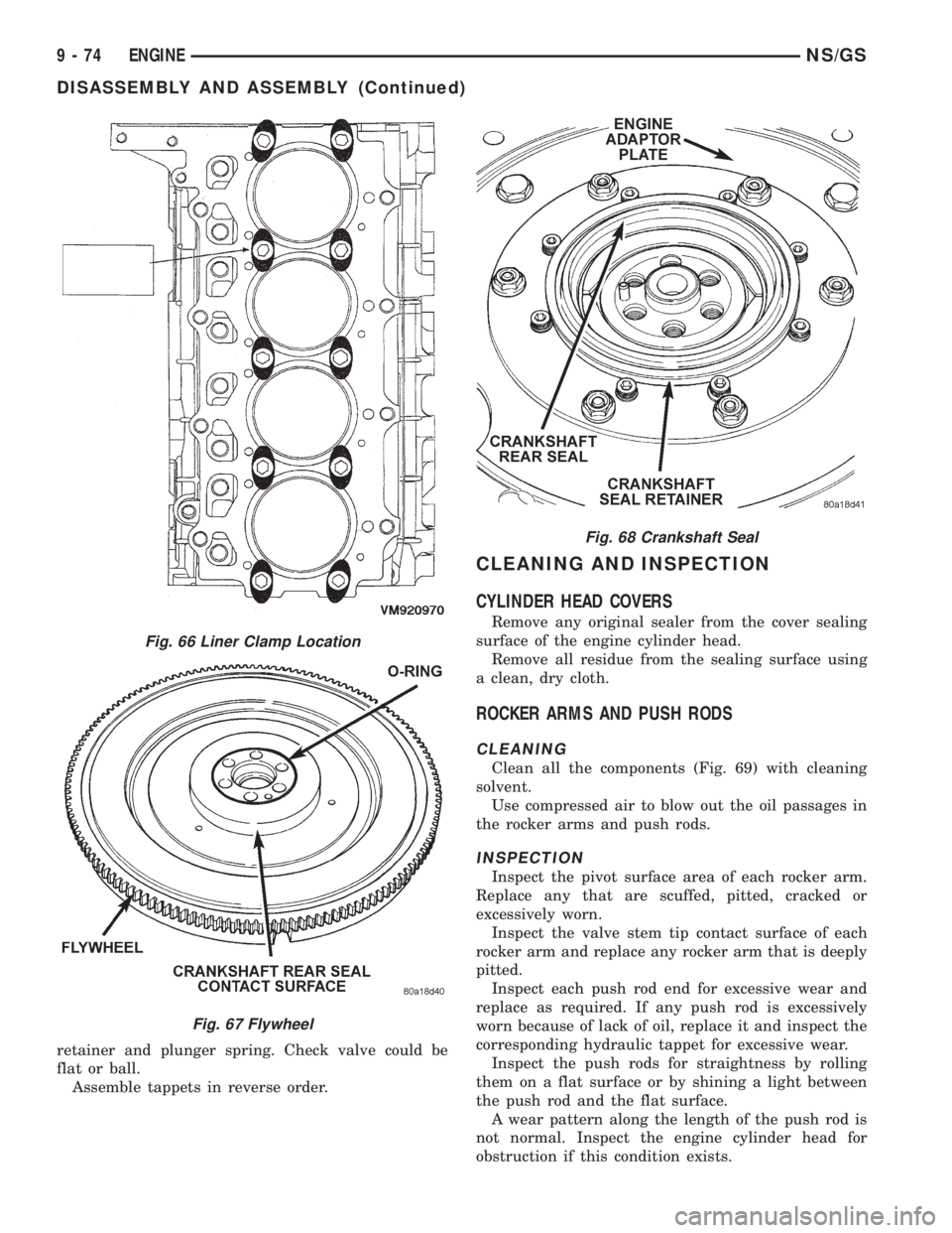
Clean all the components (Fig. 69) with cleaning
solvent.
Use compressed air to blow out the oil passages in
the rocker arms and push rods.
INSPECTION
Inspect the pivot surface area of each rocker arm.
Replace any that are scuffed, pitted, cracked or
excessively worn.
Inspect the valve stem tip contact surface of each
rocker arm and replace any rocker arm that is deeply
pitted.
Inspect each push rod end for excessive wear and
replace as required. If any push rod is excessively
worn because of lack of oil, replace it and inspect the
corresponding hydraulic tappet for excessive wear.
Inspect the push rods for straightness by rolling
them on a flat surface or by shining a light between
the push rod and the flat surface.
A wear pattern along the length of the push rod is
not normal. Inspect the engine cylinder head for
obstruction if this condition exists.
Fig. 66 Liner Clamp Location
Fig. 67 Flywheel
Fig. 68 Crankshaft Seal
9 - 74 ENGINENS/GS
DISASSEMBLY AND ASSEMBLY (Continued)
Page 1264 of 1938
a catalytic converter. Failure of the catalytic con-
verter can occur due to temperature increases caused
by unburned fuel igniting when passing through the
converter.
The use of the catalysts also involves some non-au-
tomotive problems. Unleaded gasoline must be used
to avoid poisoning the catalyst core. Do not allow
engine to operate at fast idle for extended periods
(over 5 minutes). This condition may result in exces-
sive exhaust system and floor pan temperatures.
EXHAUST GAS RECIRCULATION (EGR)
To assist in the control of oxides of nitrogen (NOx)
in engine exhaust, all engines are equipped with an
exhaust gas recirculation system. The use of exhaust
gas to dilute incoming air/fuel mixtures lowers peak
flame temperatures during combustion, thus limiting
the formation of NOx.
Exhaust gases are taken from opening in the
exhaust manifold passage to the intake manifold.
REFER TO SECTION 25 FOR A COMPLETE
DESCRIPTION, DIAGNOSIS AND SERVICE PRO-
CEDURES ON THE EXHAUST GAS RECIRCULA-
TION SYSTEM AND COMPONENTS.
HEAT SHIELDS
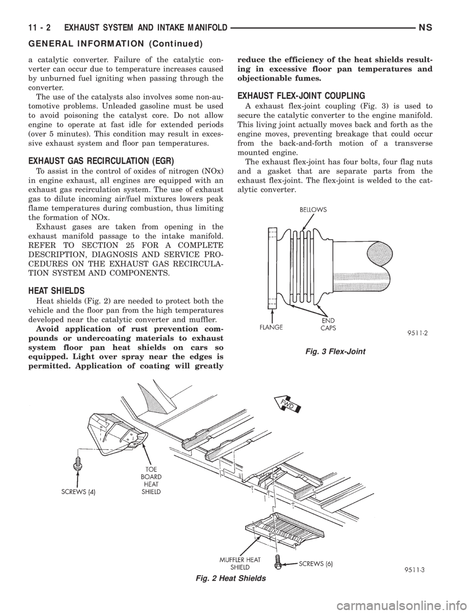
Heat shields (Fig. 2) are needed to protect both the
vehicle and the floor pan from the high temperatures
developed near the catalytic converter and muffler.
Avoid application of rust prevention com-
pounds or undercoating materials to exhaust
system floor pan heat shields on cars so
equipped. Light over spray near the edges is
permitted. Application of coating will greatlyreduce the efficiency of the heat shields result-
ing in excessive floor pan temperatures and
objectionable fumes.
EXHAUST FLEX-JOINT COUPLING
A exhaust flex-joint coupling (Fig. 3) is used to
secure the catalytic converter to the engine manifold.
This living joint actually moves back and forth as the
engine moves, preventing breakage that could occur
from the back-and-forth motion of a transverse
mounted engine.
The exhaust flex-joint has four bolts, four flag nuts
and a gasket that are separate parts from the
exhaust flex-joint. The flex-joint is welded to the cat-
alytic converter.
Fig. 2 Heat Shields
Fig. 3 Flex-Joint
11 - 2 EXHAUST SYSTEM AND INTAKE MANIFOLDNS
GENERAL INFORMATION (Continued)
Page 1265 of 1938
CAUTION: When servicing, care must be exercised
not to dent or bend the bellows of the flex-joint.
Should this occur, the flex-joint will eventually fail
and require the catalytic converter be replaced.
DESCRIPTION AND OPERATION
INTAKE/EXHAUST MANIFOLDÐ2.4L ENGINE
The intake manifold is a tuned two-piece alumi-
num casting with individual primary runners leading
from a plenum to the cylinders. The manifold is
designed to boost torque which is desired for excel-
lent engine response and usable power output.
The exhaust manifold is made of nodular cast iron
for strength and high temperatures.
INTAKE/EXHAUST MANIFOLDÐ3.0L ENGINE
The aluminum alloy manifold is a cross type with
long runners to improve air flow. The runners,
attaching below at the cylinder head, also attach
above and support an air plenum. The air plenum
chamber absorbs air pulsations created during the
suction phase of each cylinder.Both exhaust manifolds are a log style made of
ductile cast iron. Exhaust gasses, collected from the
front cylinder bank, leave the front manifold through
an end outlet and are fed through an upper crossover
tube to the rear manifold. The collected exhaust from
both manifolds are combined at the exhaust outlet, to
the exhaust pipe.
INTAKE/EXHAUST MANIFOLDÐ3.3/3.8L ENGINES
The intake manifold is a tuned two-piece semi-per-
manent mold aluminum casting with individual pri-
mary runners leading from a plenum to the
cylinders. The manifold is designed to boost torque in
the 3600 rpm range and contributes to the engine's
broad, flat torque curve, which was desired for excel-
lent engine tractability, response and usable power
output.
The intake manifold is also cored with upper level
EGR passages for balanced cylinder to cylinder EGR
distribution.
The exhaust manifolds are log type with a cross-
over and are attached directly to the cylinder heads.
They are made from nodular cast iron.
DIAGNOSIS AND TESTING
EXHAUST SYSTEM
CONDITION POSSIBLE CAUSES CORRECTION
EXCESSIVE EXHAUST
NOISE (UNDER HOOD)1. Exhaust manifold cracked or broken. 1. Replace manifold.
2. Manifold to cylinder head leak. 2. Tighten manifold and/or replace gasket.
3. EGR Valve to manifold gasket leakage. 3. Tighten fasteners or replace gasket.
4. EGR Valve to EGR tube gasket
leakage.4. Tighten fasteners or replace gasket.
5. EGR tube to manifold tube leakage. 5. Tighten tube nut.
6. Exhaust flex-joint to manifold leak. 6. Tighten joint fasteners and/or replace
gasket.
7. Exhaust flex-joint. 7. Replace catalytic converter assembly.
8. Pipe and shell noise from front exhaust
pipe.8. Characteristic of single wall pipe.
EXCESSIVE EXHAUST
NOISE1. Leak at exhaust pipe joints. 1. Tighten clamps at leaking joints.
2. Burned or rusted out muffler assembly
or exhaust pipe.2. Replace muffler resonator tailpipe
assembly or exhaust pipe with catalytic
converter assembly.
3. Burned or rusted out resonator. 3. Replace muffler resonator tailpipe
assembly.
4. Restriction in exhaust system. 4. Remove restriction, if possible, or
replace as necessary.
5. Converter material in muffler. 5. Replace muffler and converter
assemblies. Check fuel injection and
ignition systems for proper operation.
NSEXHAUST SYSTEM AND INTAKE MANIFOLD 11 - 3
GENERAL INFORMATION (Continued)