1996 CHRYSLER VOYAGER air condition
[x] Cancel search: air conditionPage 1411 of 1938
FUEL INJECTION SYSTEMÐ2.5L DIESEL ENGINE
INDEX
page page
GENERAL INFORMATION
INTRODUCTION....................... 43
DESCRIPTION AND OPERATION
AIR CONDITIONING (A/C) CONTROLSÐ
PCM INPUTS........................ 47
AIR CONDITIONING RELAYÐPCM OUTPUT . . 48
BATTERY VOLTAGEÐPCM INPUT.......... 45
BOOST PRESSURE SENSOR............. 45
BRAKE SWITCHÐPCM INPUT............. 47
DATA LINK CONNECTORÐ
PCM INPUT AND OUTPUT.............. 47
DIESEL PCM RELAYÐPCM INPUT......... 48
ENGINE COOLANT GAUGEÐPCM OUTPUT . . 48
ENGINE COOLANT TEMPERATURE SENSORÐ
PCM INPUT......................... 46
ENGINE OIL PRESSURE GAUGEÐ
PCM OUTPUT........................ 48
ENGINE SPEED SENSORÐPCM INPUT..... 46
EXHAUST GAS RECIRCULATION (EGR)
SOLENOIDÐPCM OUTPUT............. 50
FIVE VOLT POWERÐPCM OUTPUT........ 48
FUEL INJECTOR SENSORÐGROUND...... 46
FUEL TIMING SOLENOIDÐPCM OUTPUT.... 48
GLOW PLUG LAMPÐPCM OUTPUT........ 48
GLOW PLUG RELAYÐPCM OUTPUT....... 49
GLOW PLUGS......................... 49
IGNITION CIRCUIT SENSEÐPCM INPUT.... 45
NEEDLE MOVEMENT OR INSTRUMENTED
FIRST INJECTORÐPCM INPUT.......... 45
POWER GROUND...................... 45
POWERTRAIN CONTROL MODULE (PCM) . . . 44
SENSOR RETURNÐPCM INPUT (ANALOG
GROUND)........................... 45SIGNAL GROUNDÐPCM INPUT........... 45
SPEED CONTROLÐPCM INPUTS.......... 48
SPEED CONTROLÐPCM OUTPUTS........ 48
START SIGNALÐPCM INPUT............. 45
TACHOMETERÐPCM OUTPUT............ 49
VEHICLE SPEED SENSORÐPCM INPUT.... 47
VEHICLE THEFT ALARM................. 45
DIAGNOSIS AND TESTING
BOOST PRESSURE SENSOR............. 53
DIAGNOSTIC TROUBLE CODES........... 53
DIESEL DIAGNOSTICS.................. 50
DIESEL PCM RELAY TEST............... 50
ENGINE COOLANT TEMPERATURE
SENSOR TEST....................... 50
ENGINE SPEED SENSOR TEST........... 50
GLOW PLUG RELAY TEST............... 51
GLOW PLUG TEST..................... 51
RELAYSÐOPERATION/TESTING........... 52
VEHICLE SPEED SENSOR TEST........... 53
REMOVAL AND INSTALLATION
A/C CLUTCH RELAY.................... 53
DIESEL PCM RELAY.................... 53
ENGINE COOLANT TEMPERATURE
SENSOR............................ 54
ENGINE SPEED SENSOR................ 53
GLOW PLUG RELAY.................... 55
GLOW PLUGS......................... 54
POWERTRAIN CONTROL MODULE (PCM) . . . 55
VEHICLE SPEED SENSOR............... 55
SPECIFICATIONS
GLOW PLUG CURRENT DRAW............ 56
TORQUE CHARTÐ2.5L DIESEL............ 57
GENERAL INFORMATION
INTRODUCTION
This section will cover components either regulated
or controlled by the Powertrain Control Module
(PCM). The fuel heater relay, fuel heater and fuel
gauge are not operated by the PCM. These compo-
nents are controlled by the ignition (key) switch. All
other fuel system electrical components necessary to
operate the engine are controlled or regulated by the
PCM. Refer to the following PCM description for
more information.
Certain fuel system component failures may cause
a no start, or prevent the engine from running. It is
important to know that the PCM has a featurewhere, if possible, it will ignore the failed sensor, set
a code related to the sensor, and operate the engine
in a ªLimp Homeº mode. When the PCM is operating
in a ªLimp Homeº mode, the Diesel Glow Plug lamp
on the instrument panel will be constantly illumi-
nated, and the engine will most likely have a notice-
able loss of performance. An example of this would be
an Accelerator Pedal Position Sensor failure, and in
that situation, the engine would run at a constant
1100 RPM, regardless of the actual position of the
pedal. This is the most extreme of the three ªLimp
Homeº modes.
In addition to indicating that the glow plugs are
hot enough to start combustion, the Glow Plug Lamp
is also used in the diagnosis of the PCM, and when
NS/GSFUEL SYSTEMÐ2.5L DIESEL ENGINE/2.0L GAS ENGINE 14 - 43
Page 1412 of 1938
illuminated constantly, it usually indicates a problem
has been detected somewhere within the fuel system.
The DRBIII scan tool is the best method for commu-
nicating with the PCM to diagnose faults within the
system.
DESCRIPTION AND OPERATION
POWERTRAIN CONTROL MODULE (PCM)
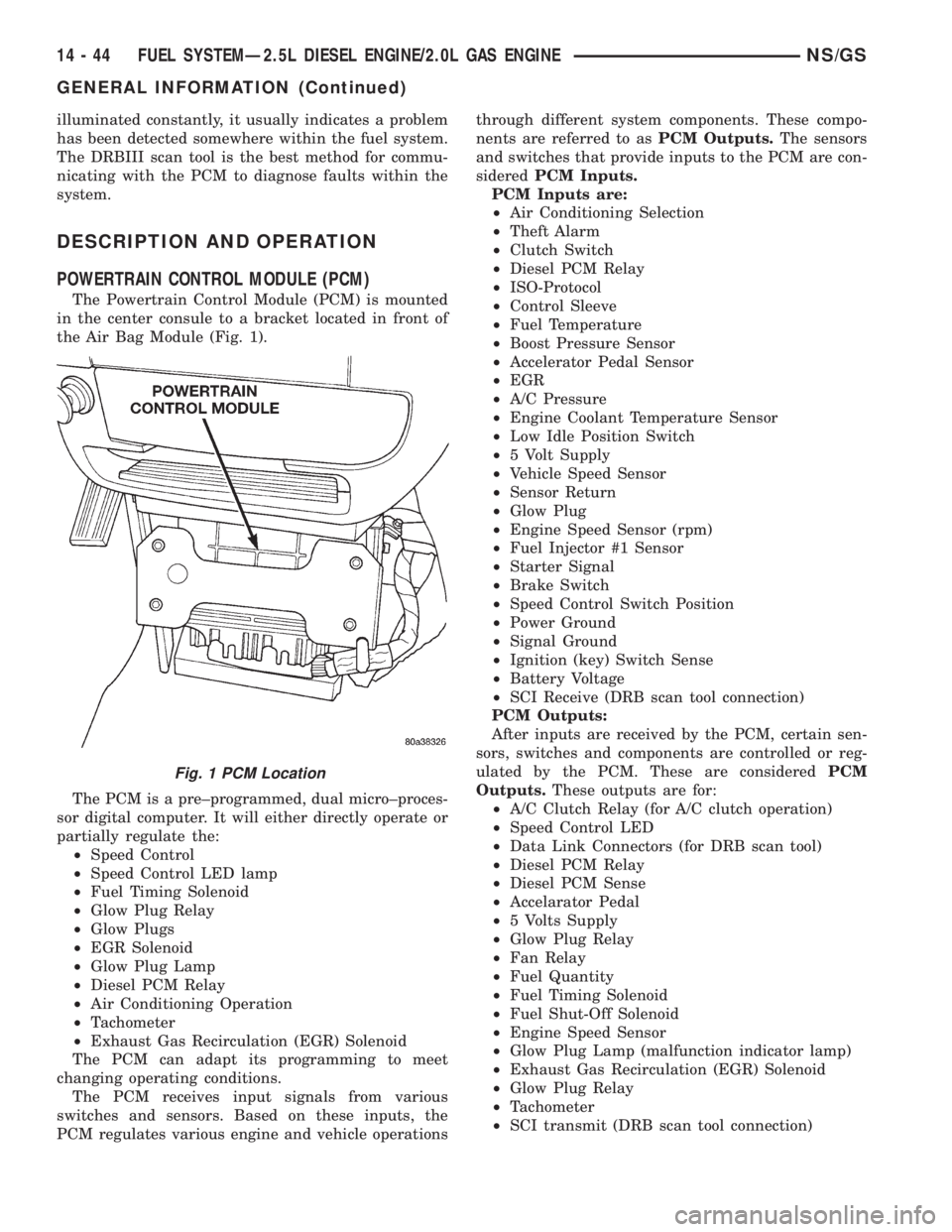
The Powertrain Control Module (PCM) is mounted
in the center consule to a bracket located in front of
the Air Bag Module (Fig. 1).
The PCM is a pre±programmed, dual micro±proces-
sor digital computer. It will either directly operate or
partially regulate the:
²Speed Control
²Speed Control LED lamp
²Fuel Timing Solenoid
²Glow Plug Relay
²Glow Plugs
²EGR Solenoid
²Glow Plug Lamp
²Diesel PCM Relay
²Air Conditioning Operation
²Tachometer
²Exhaust Gas Recirculation (EGR) Solenoid
The PCM can adapt its programming to meet
changing operating conditions.
The PCM receives input signals from various
switches and sensors. Based on these inputs, the
PCM regulates various engine and vehicle operationsthrough different system components. These compo-
nents are referred to asPCM Outputs.The sensors
and switches that provide inputs to the PCM are con-
sideredPCM Inputs.
PCM Inputs are:
²Air Conditioning Selection
²Theft Alarm
²Clutch Switch
²Diesel PCM Relay
²ISO-Protocol
²Control Sleeve
²Fuel Temperature
²Boost Pressure Sensor
²Accelerator Pedal Sensor
²EGR
²A/C Pressure
²Engine Coolant Temperature Sensor
²Low Idle Position Switch
²5 Volt Supply
²Vehicle Speed Sensor
²Sensor Return
²Glow Plug
²Engine Speed Sensor (rpm)
²Fuel Injector #1 Sensor
²Starter Signal
²Brake Switch
²Speed Control Switch Position
²Power Ground
²Signal Ground
²Ignition (key) Switch Sense
²Battery Voltage
²SCI Receive (DRB scan tool connection)
PCM Outputs:
After inputs are received by the PCM, certain sen-
sors, switches and components are controlled or reg-
ulated by the PCM. These are consideredPCM
Outputs.These outputs are for:
²A/C Clutch Relay (for A/C clutch operation)
²Speed Control LED
²Data Link Connectors (for DRB scan tool)
²Diesel PCM Relay
²Diesel PCM Sense
²Accelarator Pedal
²5 Volts Supply
²Glow Plug Relay
²Fan Relay
²Fuel Quantity
²Fuel Timing Solenoid
²Fuel Shut-Off Solenoid
²Engine Speed Sensor
²Glow Plug Lamp (malfunction indicator lamp)
²Exhaust Gas Recirculation (EGR) Solenoid
²Glow Plug Relay
²Tachometer
²SCI transmit (DRB scan tool connection)
Fig. 1 PCM Location
14 - 44 FUEL SYSTEMÐ2.5L DIESEL ENGINE/2.0L GAS ENGINENS/GS
GENERAL INFORMATION (Continued)
Page 1415 of 1938
AIR CONDITIONING (A/C) CONTROLSÐPCM
INPUTS
The A/C control system information applies to fac-
tory installed air conditioning units.
A/C REQUEST SIGNAL:When either the A/C or
Defrost mode has been selected and the A/C low and
high±pressure switches are closed, an input signal is
sent to the powertrain control module (PCM). The
PCM uses this input to cycle the A/C compressor
through the A/C relay.
If the A/C low or high±pressure switch opens, the
PCM will not receive an A/C request signal. The
PCM will then remove the ground from the A/C relay.
This will deactivate the A/C compressor clutch. Also,
if the engine coolant reaches a temperature outside
normal of its normal range, or it overheats, the PCM
will deactivate the A/C clutch.
BRAKE SWITCHÐPCM INPUT
When the brake light switch is activated, the PCM
receives an input indicating that the brakes are
being applied. After receiving this input, the PCM is
used to control the speed control system. There is a
Primary and a Secondary brake switch. The Second-
ary brake switch is closed until the brake pedal is
pressed.
DATA LINK CONNECTORÐPCM INPUT AND
OUTPUT
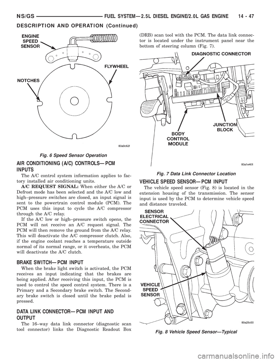
The 16±way data link connector (diagnostic scan
tool connector) links the Diagnostic Readout Box(DRB) scan tool with the PCM. The data link connec-
tor is located under the instrument panel near the
bottom of steering column (Fig. 7).
VEHICLE SPEED SENSORÐPCM INPUT
The vehicle speed sensor (Fig. 8) is located in the
extension housing of the transmission. The sensor
input is used by the PCM to determine vehicle speed
and distance traveled.
Fig. 6 Speed Sensor Operation
Fig. 7 Data Link Connector Location
Fig. 8 Vehicle Speed SensorÐTypical
NS/GSFUEL SYSTEMÐ2.5L DIESEL ENGINE/2.0L GAS ENGINE 14 - 47
DESCRIPTION AND OPERATION (Continued)
Page 1416 of 1938
The speed sensor generates 8 pulses per sensor
revolution. These signals, in conjunction with a
closed throttle signal from the throttle position sen-
sor, indicate a closed throttle deceleration to the
PCM. When the vehicle is stopped at idle, a closed
throttle signal is received by the PCM (but a speed
sensor signal is not received).
In addition to determining distance and vehicle
speed, the output from the sensor is used to control
speed control operation.
SPEED CONTROLÐPCM INPUTS
The speed control system provides five separate
inputs to the PCM; On/Off, Set, Resume/Accel, Cancel,
and Decel.. The On/Off input informs the PCM that
the speed control system has been activated. The Set
input informs the PCM that a fixed vehicle speed has
been selected. The Resume input indicates to the PCM
that the previous fixed speed is requested.
Speed control operation will start at 50 km/h±142
km/h (35±85 mph). The upper range of operation is
not restricted by vehicle speed. Inputs that affect
speed control operation are vehicle speed sensor and
throttle position sensor.
Refer to Group 8H for further speed control infor-
mation.
DIESEL PCM RELAYÐPCM INPUT
A 12 volt signal at this input indicates to the PCM
that the Diesel relay has been activated. The Diesel
relay is located in the PDC. The PDC is located next
to the battery in the engine compartment. For the
location of the relay within the PDC, refer to label on
PDC cover.
This input is used only to sense that the Diesel
relay is energized. If the PCM does not see 12 volts +
at this input when the Diesel relay should be acti-
vated, it will set a Diagnostic Trouble Code (DTC).
FIVE VOLT POWERÐPCM OUTPUT
This circuit supplies approximately 5 volts to
power the Accelerator Pedal Postion Sensor, Mass Air
Flow Sensor, and A/C Pressure Sensor.
ENGINE COOLANT GAUGEÐPCM OUTPUT
Refer to the Instrument Panel and Gauges group
for additional information.
ENGINE OIL PRESSURE GAUGEÐPCM OUTPUT
Refer to the Instrument Panel and Gauges group
for additional information.
GLOW PLUG LAMPÐPCM OUTPUT
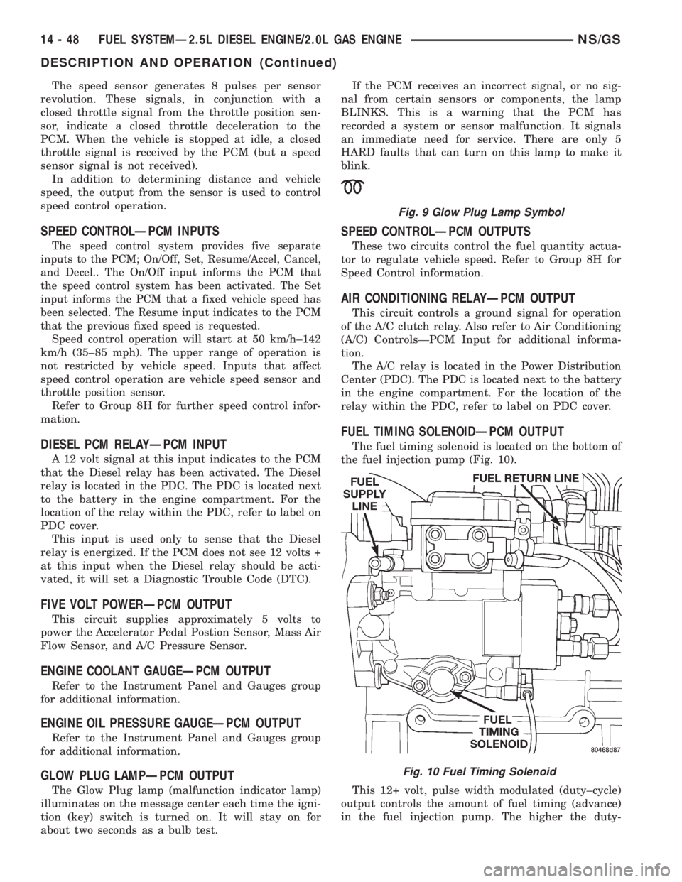
The Glow Plug lamp (malfunction indicator lamp)
illuminates on the message center each time the igni-
tion (key) switch is turned on. It will stay on for
about two seconds as a bulb test.If the PCM receives an incorrect signal, or no sig-
nal from certain sensors or components, the lamp
BLINKS. This is a warning that the PCM has
recorded a system or sensor malfunction. It signals
an immediate need for service. There are only 5
HARD faults that can turn on this lamp to make it
blink.
SPEED CONTROLÐPCM OUTPUTS
These two circuits control the fuel quantity actua-
tor to regulate vehicle speed. Refer to Group 8H for
Speed Control information.
AIR CONDITIONING RELAYÐPCM OUTPUT
This circuit controls a ground signal for operation
of the A/C clutch relay. Also refer to Air Conditioning
(A/C) ControlsÐPCM Input for additional informa-
tion.
The A/C relay is located in the Power Distribution
Center (PDC). The PDC is located next to the battery
in the engine compartment. For the location of the
relay within the PDC, refer to label on PDC cover.
FUEL TIMING SOLENOIDÐPCM OUTPUT
The fuel timing solenoid is located on the bottom of
the fuel injection pump (Fig. 10).
This 12+ volt, pulse width modulated (duty±cycle)
output controls the amount of fuel timing (advance)
in the fuel injection pump. The higher the duty-
Fig. 9 Glow Plug Lamp Symbol
Fig. 10 Fuel Timing Solenoid
14 - 48 FUEL SYSTEMÐ2.5L DIESEL ENGINE/2.0L GAS ENGINENS/GS
DESCRIPTION AND OPERATION (Continued)
Page 1423 of 1938
INSTALLATION
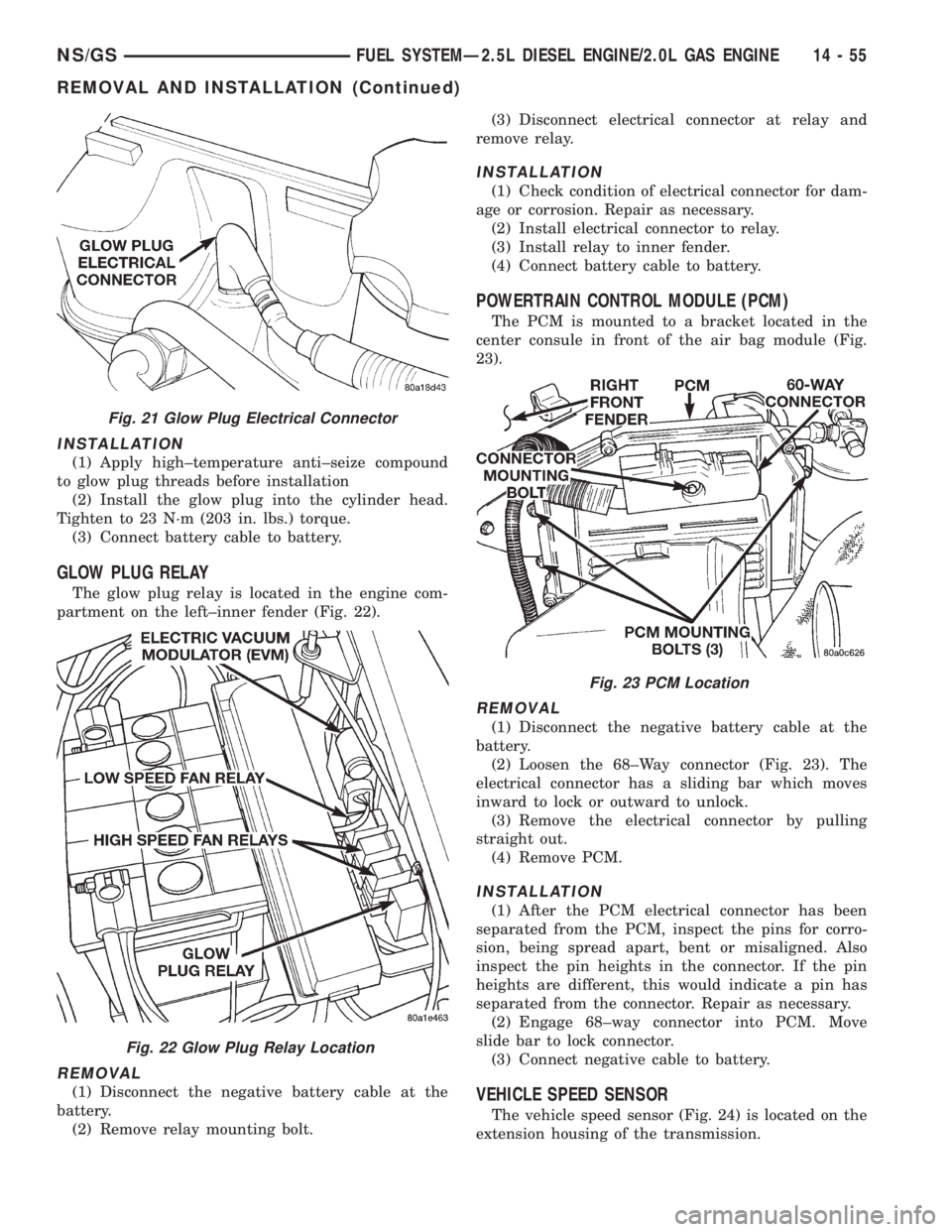
(1) Apply high±temperature anti±seize compound
to glow plug threads before installation
(2) Install the glow plug into the cylinder head.
Tighten to 23 N´m (203 in. lbs.) torque.
(3) Connect battery cable to battery.
GLOW PLUG RELAY
The glow plug relay is located in the engine com-
partment on the left±inner fender (Fig. 22).
REMOVAL
(1) Disconnect the negative battery cable at the
battery.
(2) Remove relay mounting bolt.(3) Disconnect electrical connector at relay and
remove relay.
INSTALLATION
(1) Check condition of electrical connector for dam-
age or corrosion. Repair as necessary.
(2) Install electrical connector to relay.
(3) Install relay to inner fender.
(4) Connect battery cable to battery.
POWERTRAIN CONTROL MODULE (PCM)
The PCM is mounted to a bracket located in the
center consule in front of the air bag module (Fig.
23).
REMOVAL
(1) Disconnect the negative battery cable at the
battery.
(2) Loosen the 68±Way connector (Fig. 23). The
electrical connector has a sliding bar which moves
inward to lock or outward to unlock.
(3) Remove the electrical connector by pulling
straight out.
(4) Remove PCM.
INSTALLATION
(1) After the PCM electrical connector has been
separated from the PCM, inspect the pins for corro-
sion, being spread apart, bent or misaligned. Also
inspect the pin heights in the connector. If the pin
heights are different, this would indicate a pin has
separated from the connector. Repair as necessary.
(2) Engage 68±way connector into PCM. Move
slide bar to lock connector.
(3) Connect negative cable to battery.
VEHICLE SPEED SENSOR
The vehicle speed sensor (Fig. 24) is located on the
extension housing of the transmission.
Fig. 21 Glow Plug Electrical Connector
Fig. 22 Glow Plug Relay Location
Fig. 23 PCM Location
NS/GSFUEL SYSTEMÐ2.5L DIESEL ENGINE/2.0L GAS ENGINE 14 - 55
REMOVAL AND INSTALLATION (Continued)
Page 1429 of 1938
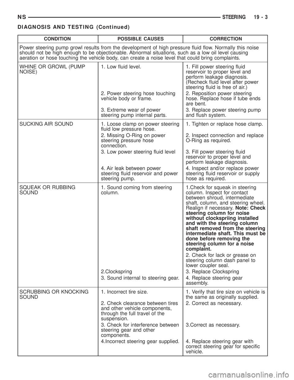
CONDITION POSSIBLE CAUSES CORRECTION
Power steering pump growl results from the development of high pressure fluid flow. Normally this noise
should not be high enough to be objectionable. Abnormal situations, such as a low oil level causing
aeration or hose touching the vehicle body, can create a noise level that could bring complaints.
WHINE OR GROWL (PUMP
NOISE)1. Low fluid level. 1. Fill power steering fluid
reservoir to proper level and
perform leakage diagnosis.
(Recheck fluid level after power
steering fluid is free of air.)
2. Power steering hose touching
vehicle body or frame.2. Reposition power steering
hose. Replace hose if tube ends
are bent.
3. Extreme wear of power
steering pump internal parts.3. Replace power steering pump
and flush system.
SUCKING AIR SOUND 1. Loose clamp on power steering
fluid low pressure hose.1. Tighten or replace hose clamp.
2. Missing O-Ring on power
steering pressure hose
connection.2. Inspect connection and replace
O-Ring as required.
3. Low power steering fluid level 3. Fill power steering fluid
reservoir to proper level and
perform leakage diagnosis.
4. Air leak between power
steering fluid reservoir and power
steering pump.4. Inspect and/or replace power
steering fluid reservoir or supply
hose as required.
SQUEAK OR RUBBING
SOUND1. Sound coming from steering
column.1.Check for squeak in steering
column. Inspect for contact
between shroud, intermediate
shaft, column, and steering wheel.
Realign if necessary.Note: Check
steering column for noise
without clockspriing installed
and with the steering column
shaft removed from the steering
intermediate shaft. This must be
done before removing the
steering column for a noise
complaint.
2. Check for lack or grease on
steering column dash panel to
lower coupler seal.
2.Clockspring 3. Replace Clockspring
3. Sound internal to steering gear. 4. Replace steering gear
assembly.
SCRUBBING OR KNOCKING
SOUND1. Incorrect tire size. 1. Verify that tire size on vehicle is
the same as originally supplied.
2. Check clearance between tires
and other vehicle components,
through the full travel of the
suspension.2. Correct as necessary.
3. Check for interference between
steering gear and other
components.3.Correct as necessary.
4.Incorrect steering gear supplied. 4. Replace steering gear with
correct steering gear for specific
vehicle.
NSSTEERING 19 - 3
DIAGNOSIS AND TESTING (Continued)
Page 1430 of 1938
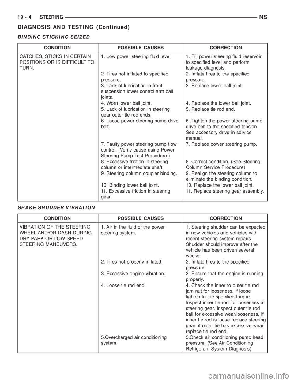
BINDING STICKING SEIZED
SHAKE SHUDDER VIBRATION
CONDITION POSSIBLE CAUSES CORRECTION
CATCHES, STICKS IN CERTAIN
POSITIONS OR IS DIFFICULT TO
TURN.1. Low power steering fluid level. 1. Fill power steering fluid reservoir
to specified level and perform
leakage diagnosis.
2. Tires not inflated to specified
pressure.2. Inflate tires to the specified
pressure.
3. Lack of lubrication in front
suspension lower control arm ball
joints.3. Replace lower ball joint.
4. Worn lower ball joint. 4. Replace the lower ball joint.
5. Lack of lubrication in steering
gear outer tie rod ends.5. Replace tie rod end.
6. Loose power steering pump drive
belt.6. Tighten the power steering pump
drive belt to the specified tension.
See accessory drive in service
manual.
7. Faulty power steering pump flow
control. (Verify cause using Power
Steering Pump Test Procedure.)7. Replace power steering pump.
8. Excessive friction in steering
column or intermediate shaft.8. Correct condition. (See Steering
Column Service Procedure)
9. Steering column coupler binding. 9. Realign the steering column to
eliminate the binding condition.
10. Binding lower ball joint. 10. Replace the lower ball joint.
11. Excessive friction in steering
gear.11. Replace steering gear assembly.
CONDITION POSSIBLE CAUSES CORRECTION
VIBRATION OF THE STEERING
WHEEL AND/OR DASH DURING
DRY PARK OR LOW SPEED
STEERING MANEUVERS.1. Air in the fluid of the power
steering system.1. Steering shudder can be expected
in new vehicles and vehicles with
recent steering system repairs.
Shudder should improve after the
vehicle has been driven several
weeks.
2. Tires not properly inflated. 2. Inflate tires to the specified
pressure.
3. Excessive engine vibration. 3. Ensure that the engine is running
properly.
4. Loose tie rod end. 4. Check the inner to outer tie rod
jam nut for looseness. If loose
tighten to the specified torque.
Inspect inner tie rod for looseness at
steering gear. Inspect outer tie rod
ball for excessive wear/looseness. If
inner tie rod is loose replace steering
gear, if outer tie has excessive wear
replace tie rod end.
5.Overcharged air conditioning
system.5.Check air conditioning pump head
pressure. (See Air Conditioning
Refrigerant System Diagnosis)
19 - 4 STEERINGNS
DIAGNOSIS AND TESTING (Continued)
Page 1432 of 1938
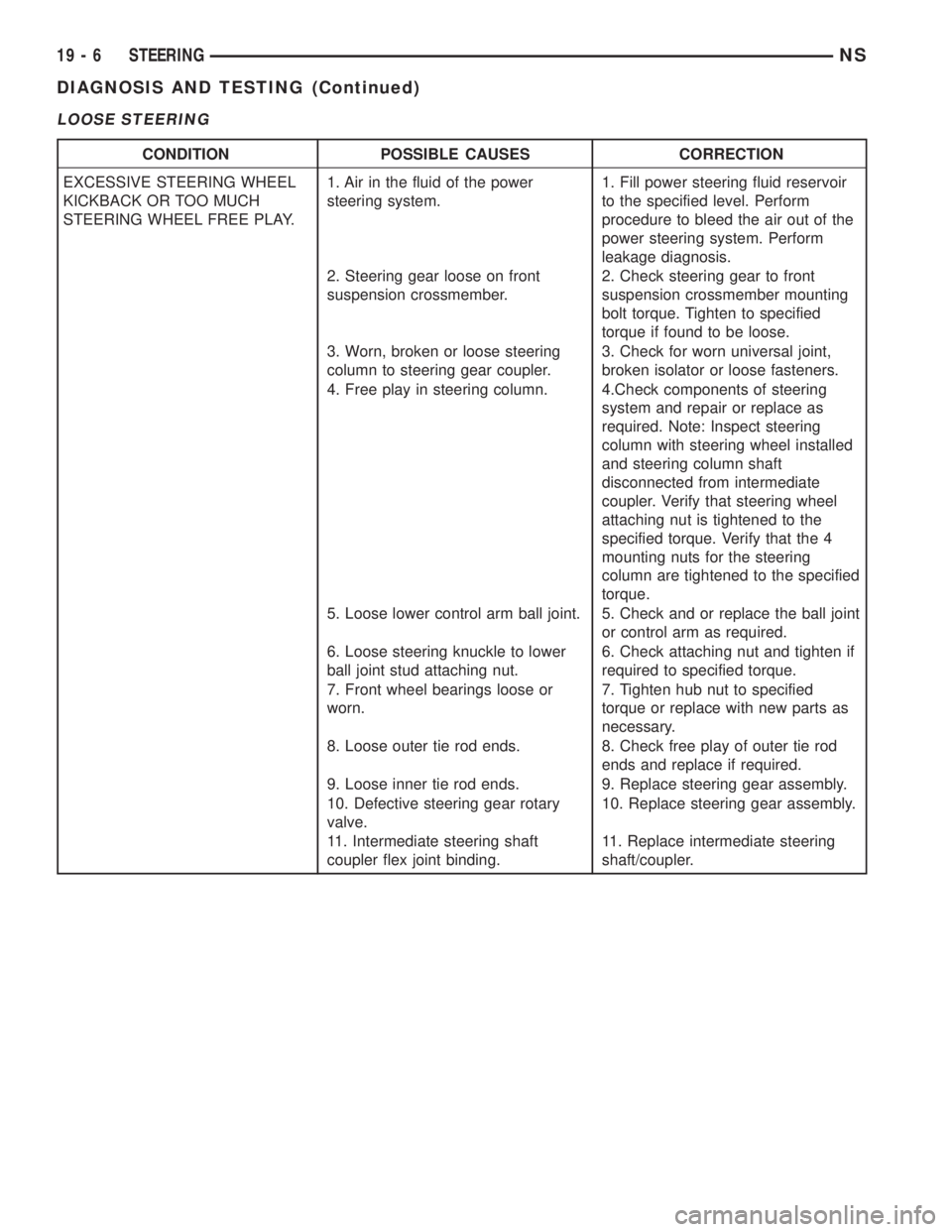
LOOSE STEERING
CONDITION POSSIBLE CAUSES CORRECTION
EXCESSIVE STEERING WHEEL
KICKBACK OR TOO MUCH
STEERING WHEEL FREE PLAY.1. Air in the fluid of the power
steering system.1. Fill power steering fluid reservoir
to the specified level. Perform
procedure to bleed the air out of the
power steering system. Perform
leakage diagnosis.
2. Steering gear loose on front
suspension crossmember.2. Check steering gear to front
suspension crossmember mounting
bolt torque. Tighten to specified
torque if found to be loose.
3. Worn, broken or loose steering
column to steering gear coupler.3. Check for worn universal joint,
broken isolator or loose fasteners.
4. Free play in steering column. 4.Check components of steering
system and repair or replace as
required. Note: Inspect steering
column with steering wheel installed
and steering column shaft
disconnected from intermediate
coupler. Verify that steering wheel
attaching nut is tightened to the
specified torque. Verify that the 4
mounting nuts for the steering
column are tightened to the specified
torque.
5. Loose lower control arm ball joint. 5. Check and or replace the ball joint
or control arm as required.
6. Loose steering knuckle to lower
ball joint stud attaching nut.6. Check attaching nut and tighten if
required to specified torque.
7. Front wheel bearings loose or
worn.7. Tighten hub nut to specified
torque or replace with new parts as
necessary.
8. Loose outer tie rod ends. 8. Check free play of outer tie rod
ends and replace if required.
9. Loose inner tie rod ends. 9. Replace steering gear assembly.
10. Defective steering gear rotary
valve.10. Replace steering gear assembly.
11. Intermediate steering shaft
coupler flex joint binding.11. Replace intermediate steering
shaft/coupler.
19 - 6 STEERINGNS
DIAGNOSIS AND TESTING (Continued)