1996 CHRYSLER VOYAGER door lock
[x] Cancel search: door lockPage 1768 of 1938
FUEL FILL DOOR BLOCKER LATCH
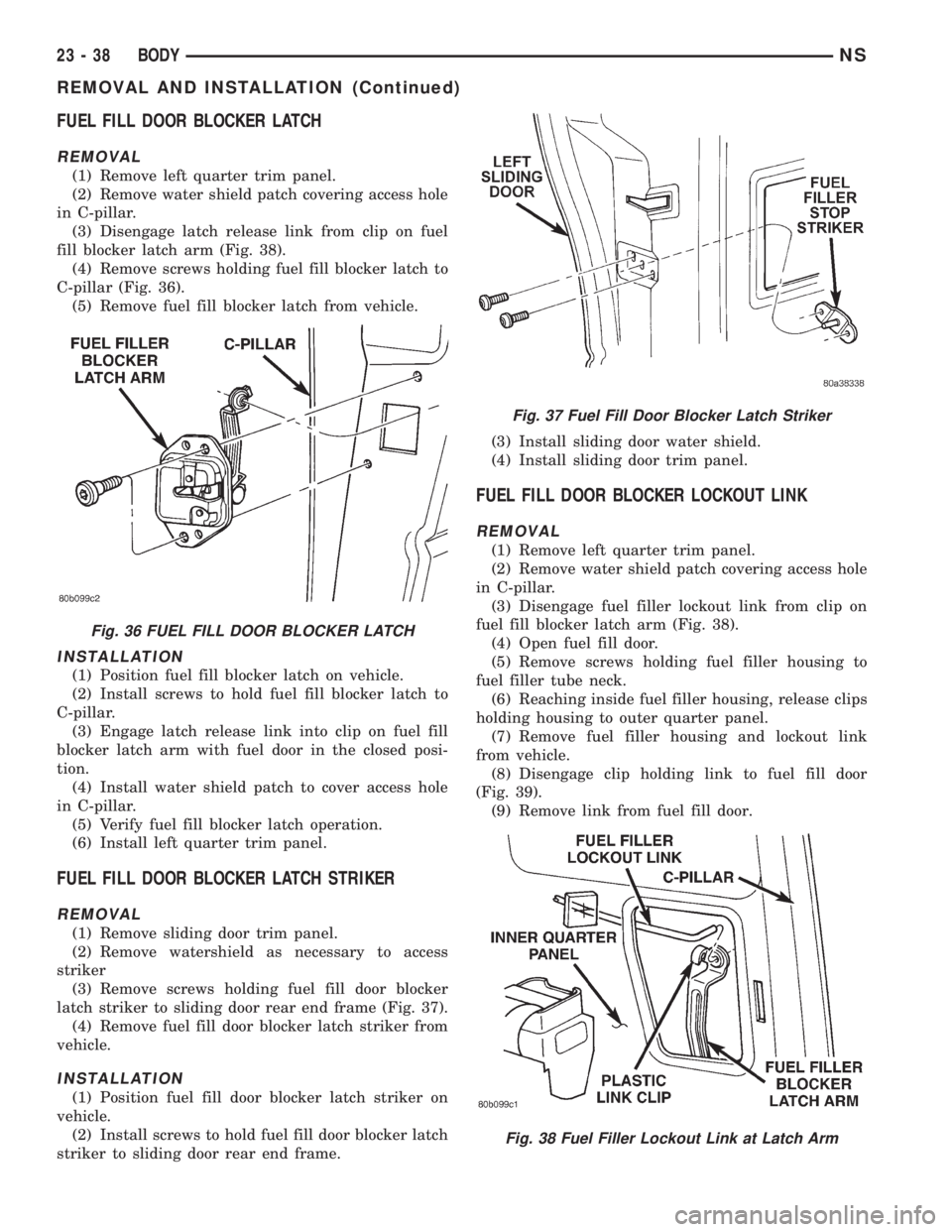
REMOVAL
(1) Remove left quarter trim panel.
(2) Remove water shield patch covering access hole
in C-pillar.
(3) Disengage latch release link from clip on fuel
fill blocker latch arm (Fig. 38).
(4) Remove screws holding fuel fill blocker latch to
C-pillar (Fig. 36).
(5) Remove fuel fill blocker latch from vehicle.
INSTALLATION
(1) Position fuel fill blocker latch on vehicle.
(2) Install screws to hold fuel fill blocker latch to
C-pillar.
(3) Engage latch release link into clip on fuel fill
blocker latch arm with fuel door in the closed posi-
tion.
(4) Install water shield patch to cover access hole
in C-pillar.
(5) Verify fuel fill blocker latch operation.
(6) Install left quarter trim panel.
FUEL FILL DOOR BLOCKER LATCH STRIKER
REMOVAL
(1) Remove sliding door trim panel.
(2) Remove watershield as necessary to access
striker
(3) Remove screws holding fuel fill door blocker
latch striker to sliding door rear end frame (Fig. 37).
(4) Remove fuel fill door blocker latch striker from
vehicle.
INSTALLATION
(1) Position fuel fill door blocker latch striker on
vehicle.
(2) Install screws to hold fuel fill door blocker latch
striker to sliding door rear end frame.(3) Install sliding door water shield.
(4) Install sliding door trim panel.
FUEL FILL DOOR BLOCKER LOCKOUT LINK
REMOVAL
(1) Remove left quarter trim panel.
(2) Remove water shield patch covering access hole
in C-pillar.
(3) Disengage fuel filler lockout link from clip on
fuel fill blocker latch arm (Fig. 38).
(4) Open fuel fill door.
(5) Remove screws holding fuel filler housing to
fuel filler tube neck.
(6) Reaching inside fuel filler housing, release clips
holding housing to outer quarter panel.
(7) Remove fuel filler housing and lockout link
from vehicle.
(8) Disengage clip holding link to fuel fill door
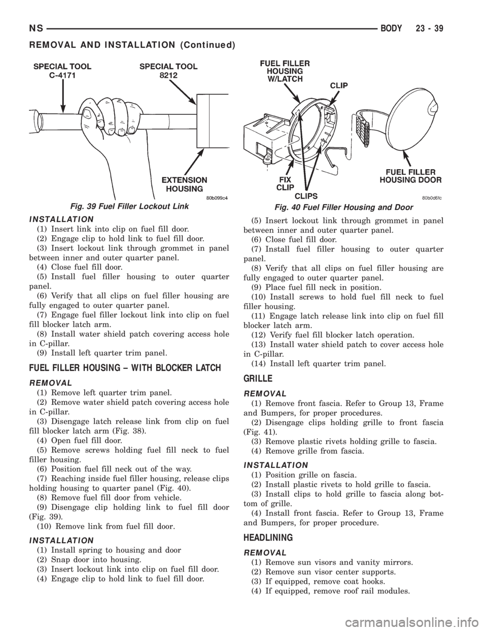
(Fig. 39).
(9) Remove link from fuel fill door.
Fig. 36 FUEL FILL DOOR BLOCKER LATCH
Fig. 37 Fuel Fill Door Blocker Latch Striker
Fig. 38 Fuel Filler Lockout Link at Latch Arm
23 - 38 BODYNS
REMOVAL AND INSTALLATION (Continued)
Page 1769 of 1938
INSTALLATION
(1) Insert link into clip on fuel fill door.
(2) Engage clip to hold link to fuel fill door.
(3) Insert lockout link through grommet in panel
between inner and outer quarter panel.
(4) Close fuel fill door.
(5) Install fuel filler housing to outer quarter
panel.
(6) Verify that all clips on fuel filler housing are
fully engaged to outer quarter panel.
(7) Engage fuel filler lockout link into clip on fuel
fill blocker latch arm.
(8) Install water shield patch covering access hole
in C-pillar.
(9) Install left quarter trim panel.
FUEL FILLER HOUSING ± WITH BLOCKER LATCH
REMOVAL
(1) Remove left quarter trim panel.
(2) Remove water shield patch covering access hole
in C-pillar.
(3) Disengage latch release link from clip on fuel
fill blocker latch arm (Fig. 38).
(4) Open fuel fill door.
(5) Remove screws holding fuel fill neck to fuel
filler housing.
(6) Position fuel fill neck out of the way.
(7) Reaching inside fuel filler housing, release clips
holding housing to quarter panel (Fig. 40).
(8) Remove fuel fill door from vehicle.
(9) Disengage clip holding link to fuel fill door
(Fig. 39).
(10) Remove link from fuel fill door.
INSTALLATION
(1) Install spring to housing and door
(2) Snap door into housing.
(3) Insert lockout link into clip on fuel fill door.
(4) Engage clip to hold link to fuel fill door.(5) Insert lockout link through grommet in panel
between inner and outer quarter panel.
(6) Close fuel fill door.
(7) Install fuel filler housing to outer quarter
panel.
(8) Verify that all clips on fuel filler housing are
fully engaged to outer quarter panel.
(9) Place fuel fill neck in position.
(10) Install screws to hold fuel fill neck to fuel
filler housing.
(11) Engage latch release link into clip on fuel fill
blocker latch arm.
(12) Verify fuel fill blocker latch operation.
(13) Install water shield patch to cover access hole
in C-pillar.
(14) Install left quarter trim panel.
GRILLE
REMOVAL
(1) Remove front fascia. Refer to Group 13, Frame
and Bumpers, for proper procedures.
(2) Disengage clips holding grille to front fascia
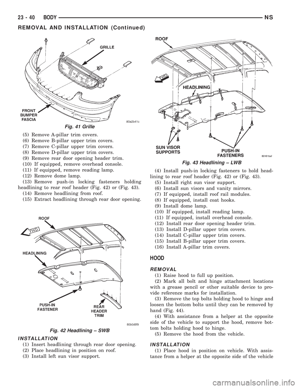
(Fig. 41).
(3) Remove plastic rivets holding grille to fascia.
(4) Remove grille from fascia.
INSTALLATION
(1) Position grille on fascia.
(2) Install plastic rivets to hold grille to fascia.
(3) Install clips to hold grille to fascia along bot-
tom of grille.
(4) Install front fascia. Refer to Group 13, Frame
and Bumpers, for proper procedure.
HEADLINING
REMOVAL
(1) Remove sun visors and vanity mirrors.
(2) Remove sun visor center supports.
(3) If equipped, remove coat hooks.
(4) If equipped, remove roof rail modules.
Fig. 39 Fuel Filler Lockout LinkFig. 40 Fuel Filler Housing and Door
NSBODY 23 - 39
REMOVAL AND INSTALLATION (Continued)
Page 1770 of 1938
(5) Remove A-pillar trim covers.
(6) Remove B-pillar upper trim covers.
(7) Remove C-pillar upper trim covers.
(8) Remove D-pillar upper trim covers.
(9) Remove rear door opening header trim.
(10) If equipped, remove overhead console.
(11) If equipped, remove reading lamp.
(12) Remove dome lamp.
(13) Remove push-in locking fasteners holding
headlining to rear roof header (Fig. 42) or (Fig. 43).
(14) Remove headlining from roof.
(15) Extract headlining through rear door opening.
INSTALLATION
(1) Insert headlining through rear door opening.
(2) Place headlining in position on roof.
(3) Install left sun visor support.(4) Install push-in locking fasteners to hold head-
lining to rear roof header (Fig. 42) or (Fig. 43).
(5) Install right sun visor support.
(6) Install sun visors and vanity mirrors.
(7) If equipped, install roof rail modules.
(8) If equipped, install coat hooks.
(9) Install dome lamp.
(10) If equipped, install reading lamp.
(11) If equipped, install overhead console.
(12) Install rear door opening header trim.
(13) Install D-pillar upper trim covers.
(14) Install C-pillar upper trim covers.
(15) Install B-pillar upper trim covers.
(16) Install A-pillar trim covers.
HOOD
REMOVAL
(1) Raise hood to full up position.
(2) Mark all bolt and hinge attachment locations
with a grease pencil or other suitable device to pro-
vide reference marks for installation.
(3) Remove the top bolts holding hood to hinge and
loosen the bottom bolts until they can be removed by
hand (Fig. 44).
(4) With assistance from a helper at the opposite
side of the vehicle to support the hood, remove bot-
tom bolts holding hood to hinge.
(5) Remove the hood from the vehicle.
INSTALLATION
(1) Place hood in position on vehicle. With assis-
tance from a helper at the opposite side of the vehicle
Fig. 41 Grille
Fig. 42 Headlining ± SWB
Fig. 43 Headlining ± LWB
23 - 40 BODYNS
REMOVAL AND INSTALLATION (Continued)
Page 1779 of 1938
(4) Connect VTSS switch from back of lock cylin-
der, if equipped.
(5) Engage outside handle link to clip on liftgate
latch.
(6) Install lock link, if equipped.
(7) Install power lock motor.
(8) Verify liftgate operation. Adjust as necessary.
(9) Install liftgate trim panel.
LIFTGATE PROP ASSEMBLY
REMOVAL
(1) Release liftgate latch and open liftgate.
(2) Support liftgate on a suitable lifting device.
(3) Pull liftgate opening weatherstrip from D-pillar
flange next to prop assembly end pivot.
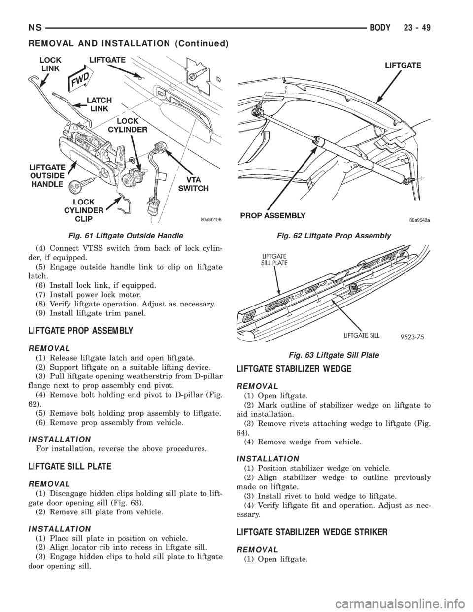
(4) Remove bolt holding end pivot to D-pillar (Fig.
62).
(5) Remove bolt holding prop assembly to liftgate.
(6) Remove prop assembly from vehicle.
INSTALLATION
For installation, reverse the above procedures.
LIFTGATE SILL PLATE
REMOVAL
(1) Disengage hidden clips holding sill plate to lift-
gate door opening sill (Fig. 63).
(2) Remove sill plate from vehicle.
INSTALLATION
(1) Place sill plate in position on vehicle.
(2) Align locator rib into recess in liftgate sill.
(3) Engage hidden clips to hold sill plate to liftgate
door opening sill.
LIFTGATE STABILIZER WEDGE
REMOVAL
(1) Open liftgate.
(2) Mark outline of stabilizer wedge on liftgate to
aid installation.
(3) Remove rivets attaching wedge to liftgate (Fig.
64).
(4) Remove wedge from vehicle.
INSTALLATION
(1) Position stabilizer wedge on vehicle.
(2) Align stabilizer wedge to outline previously
made on liftgate.
(3) Install rivet to hold wedge to liftgate.
(4) Verify liftgate fit and operation. Adjust as nec-
essary.
LIFTGATE STABILIZER WEDGE STRIKER
REMOVAL
(1) Open liftgate.
Fig. 61 Liftgate Outside HandleFig. 62 Liftgate Prop Assembly
Fig. 63 Liftgate Sill Plate
NSBODY 23 - 49
REMOVAL AND INSTALLATION (Continued)
Page 1798 of 1938
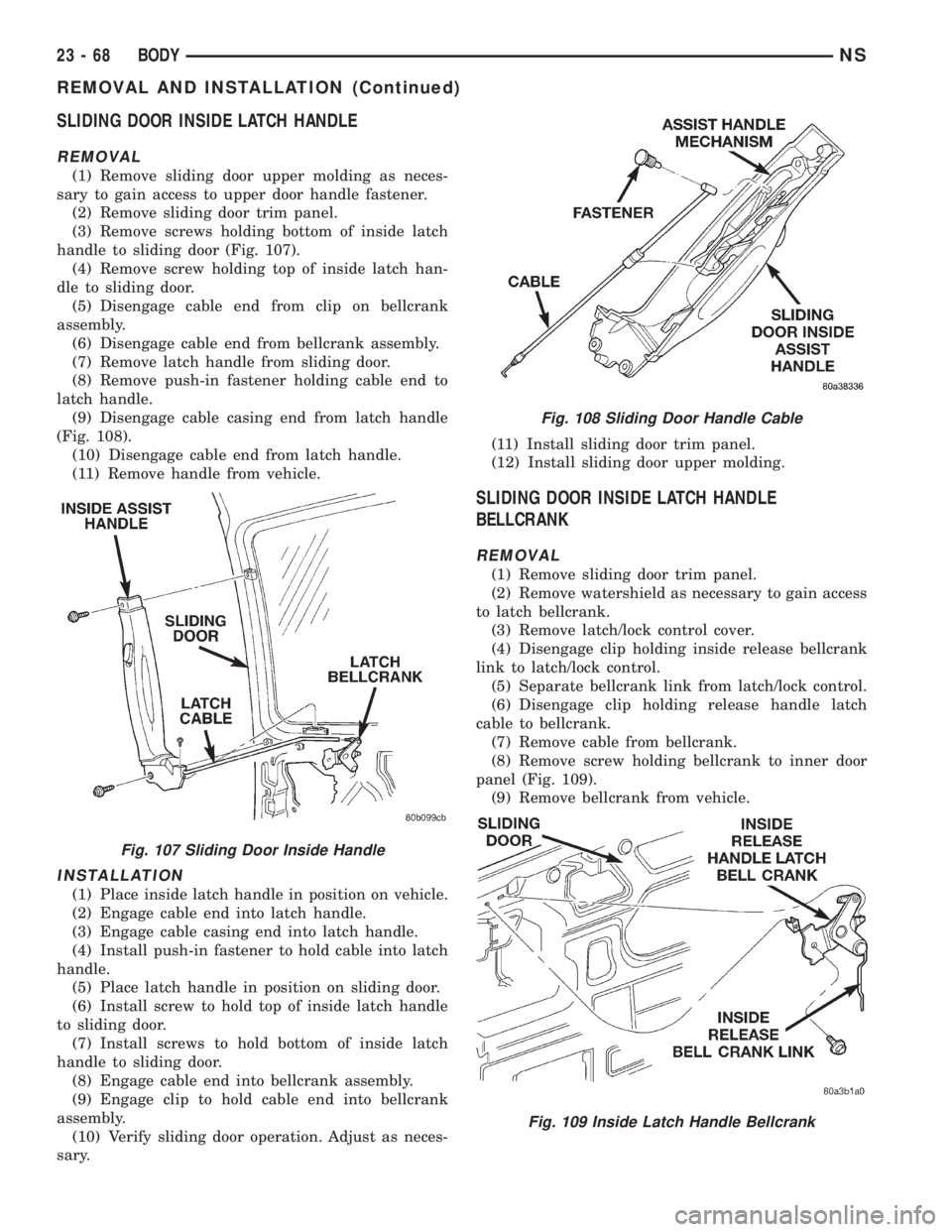
SLIDING DOOR INSIDE LATCH HANDLE
REMOVAL
(1) Remove sliding door upper molding as neces-
sary to gain access to upper door handle fastener.
(2) Remove sliding door trim panel.
(3) Remove screws holding bottom of inside latch
handle to sliding door (Fig. 107).
(4) Remove screw holding top of inside latch han-
dle to sliding door.
(5) Disengage cable end from clip on bellcrank
assembly.
(6) Disengage cable end from bellcrank assembly.
(7) Remove latch handle from sliding door.
(8) Remove push-in fastener holding cable end to
latch handle.
(9) Disengage cable casing end from latch handle
(Fig. 108).
(10) Disengage cable end from latch handle.
(11) Remove handle from vehicle.
INSTALLATION
(1) Place inside latch handle in position on vehicle.
(2) Engage cable end into latch handle.
(3) Engage cable casing end into latch handle.
(4) Install push-in fastener to hold cable into latch
handle.
(5) Place latch handle in position on sliding door.
(6) Install screw to hold top of inside latch handle
to sliding door.
(7) Install screws to hold bottom of inside latch
handle to sliding door.
(8) Engage cable end into bellcrank assembly.
(9) Engage clip to hold cable end into bellcrank
assembly.
(10) Verify sliding door operation. Adjust as neces-
sary.(11) Install sliding door trim panel.
(12) Install sliding door upper molding.
SLIDING DOOR INSIDE LATCH HANDLE
BELLCRANK
REMOVAL
(1) Remove sliding door trim panel.
(2) Remove watershield as necessary to gain access
to latch bellcrank.
(3) Remove latch/lock control cover.
(4) Disengage clip holding inside release bellcrank
link to latch/lock control.
(5) Separate bellcrank link from latch/lock control.
(6) Disengage clip holding release handle latch
cable to bellcrank.
(7) Remove cable from bellcrank.
(8) Remove screw holding bellcrank to inner door
panel (Fig. 109).
(9) Remove bellcrank from vehicle.
Fig. 107 Sliding Door Inside Handle
Fig. 108 Sliding Door Handle Cable
Fig. 109 Inside Latch Handle Bellcrank
23 - 68 BODYNS
REMOVAL AND INSTALLATION (Continued)
Page 1799 of 1938
INSTALLATION
(1) Position bellcrank on vehicle.
(2) Install screw holding bellcrank to inner door
panel.
(3) Position cable from bellcrank.
(4) Engage clip to hold release handle latch cable
to bellcrank.
(5) Position bellcrank link on latch/lock control.
(6) Engage clip to hold inside release bellcrank
link to latch/lock control.
(7) Install latch/lock control cover.
(8) Install watershield.
(9) Install sliding door trim panel.
SLIDING DOOR INSIDE LATCH RELEASE
MECHANISM
REMOVAL
(1) Remove sliding door inside latch handle.
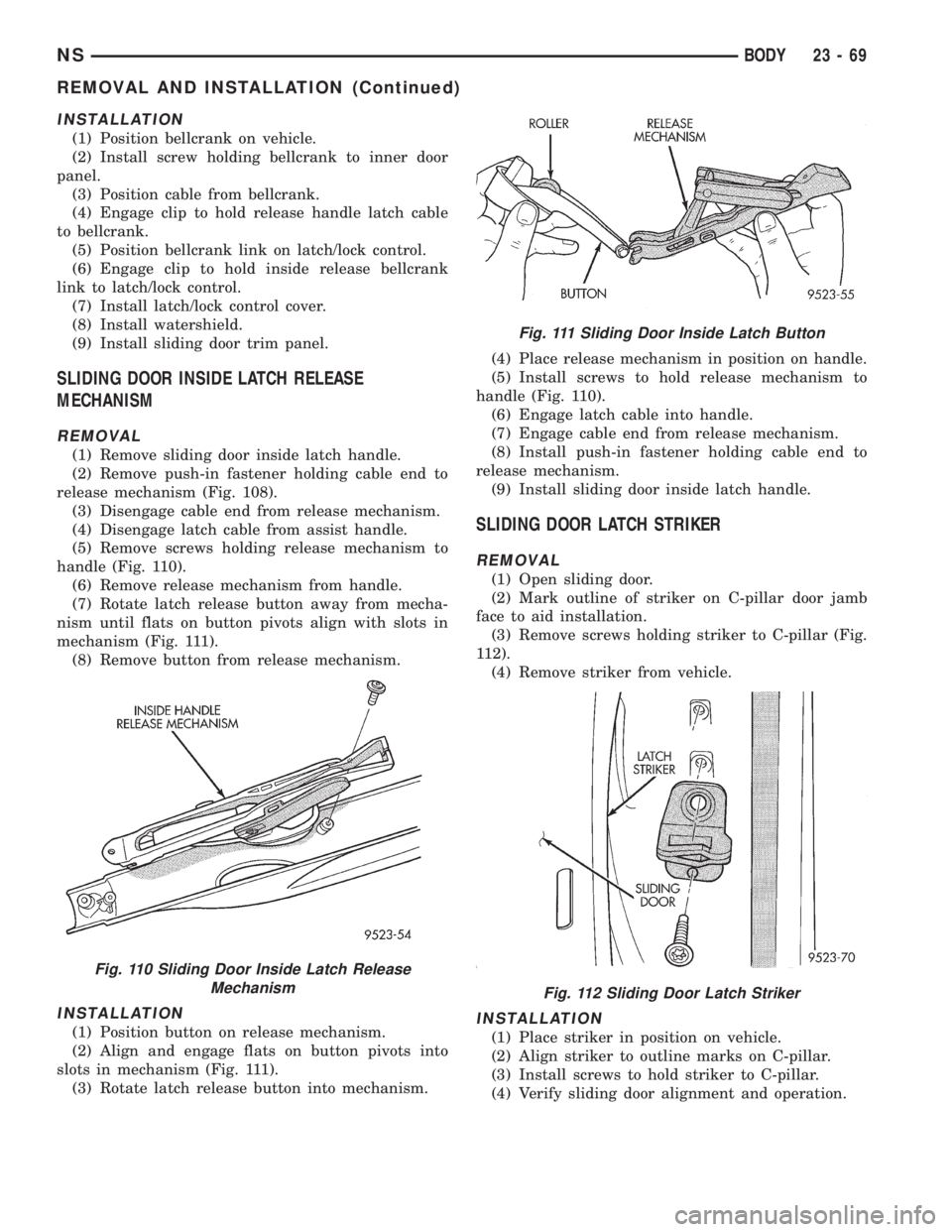
(2) Remove push-in fastener holding cable end to
release mechanism (Fig. 108).
(3) Disengage cable end from release mechanism.
(4) Disengage latch cable from assist handle.
(5) Remove screws holding release mechanism to
handle (Fig. 110).
(6) Remove release mechanism from handle.
(7) Rotate latch release button away from mecha-
nism until flats on button pivots align with slots in
mechanism (Fig. 111).
(8) Remove button from release mechanism.
INSTALLATION
(1) Position button on release mechanism.
(2) Align and engage flats on button pivots into
slots in mechanism (Fig. 111).
(3) Rotate latch release button into mechanism.(4) Place release mechanism in position on handle.
(5) Install screws to hold release mechanism to
handle (Fig. 110).
(6) Engage latch cable into handle.
(7) Engage cable end from release mechanism.
(8) Install push-in fastener holding cable end to
release mechanism.
(9) Install sliding door inside latch handle.
SLIDING DOOR LATCH STRIKER
REMOVAL
(1) Open sliding door.
(2) Mark outline of striker on C-pillar door jamb
face to aid installation.
(3) Remove screws holding striker to C-pillar (Fig.
112).
(4) Remove striker from vehicle.
INSTALLATION
(1) Place striker in position on vehicle.
(2) Align striker to outline marks on C-pillar.
(3) Install screws to hold striker to C-pillar.
(4) Verify sliding door alignment and operation.
Fig. 110 Sliding Door Inside Latch Release
Mechanism
Fig. 111 Sliding Door Inside Latch Button
Fig. 112 Sliding Door Latch Striker
NSBODY 23 - 69
REMOVAL AND INSTALLATION (Continued)
Page 1800 of 1938
SLIDING DOOR LATCH/LOCK CONTROL
REMOVAL
(1) Remove sliding door trim panel.
(2) Remove sliding door stop bumper.
(3) Remove sound pad, if equipped.
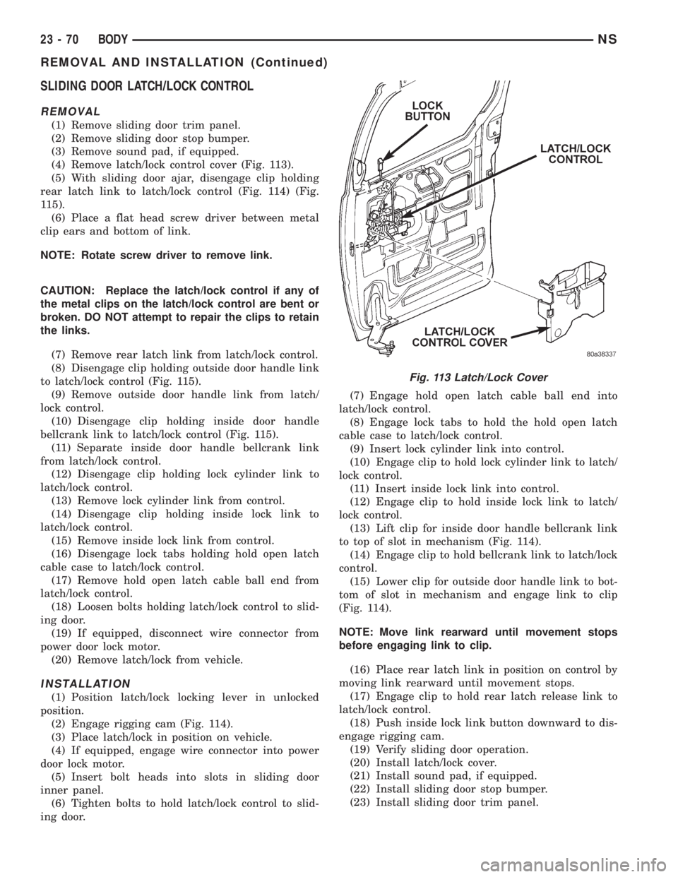
(4) Remove latch/lock control cover (Fig. 113).
(5) With sliding door ajar, disengage clip holding
rear latch link to latch/lock control (Fig. 114) (Fig.
115).
(6) Place a flat head screw driver between metal
clip ears and bottom of link.
NOTE: Rotate screw driver to remove link.
CAUTION: Replace the latch/lock control if any of
the metal clips on the latch/lock control are bent or
broken. DO NOT attempt to repair the clips to retain
the links.
(7) Remove rear latch link from latch/lock control.
(8) Disengage clip holding outside door handle link
to latch/lock control (Fig. 115).
(9) Remove outside door handle link from latch/
lock control.
(10) Disengage clip holding inside door handle
bellcrank link to latch/lock control (Fig. 115).
(11) Separate inside door handle bellcrank link
from latch/lock control.
(12) Disengage clip holding lock cylinder link to
latch/lock control.
(13) Remove lock cylinder link from control.
(14) Disengage clip holding inside lock link to
latch/lock control.
(15) Remove inside lock link from control.
(16) Disengage lock tabs holding hold open latch
cable case to latch/lock control.
(17) Remove hold open latch cable ball end from
latch/lock control.
(18) Loosen bolts holding latch/lock control to slid-
ing door.
(19) If equipped, disconnect wire connector from
power door lock motor.
(20) Remove latch/lock from vehicle.
INSTALLATION
(1) Position latch/lock locking lever in unlocked
position.
(2) Engage rigging cam (Fig. 114).
(3) Place latch/lock in position on vehicle.
(4) If equipped, engage wire connector into power
door lock motor.
(5) Insert bolt heads into slots in sliding door
inner panel.
(6) Tighten bolts to hold latch/lock control to slid-
ing door.(7) Engage hold open latch cable ball end into
latch/lock control.
(8) Engage lock tabs to hold the hold open latch
cable case to latch/lock control.
(9) Insert lock cylinder link into control.
(10) Engage clip to hold lock cylinder link to latch/
lock control.
(11) Insert inside lock link into control.
(12) Engage clip to hold inside lock link to latch/
lock control.
(13) Lift clip for inside door handle bellcrank link
to top of slot in mechanism (Fig. 114).
(14) Engage clip to hold bellcrank link to latch/lock
control.
(15) Lower clip for outside door handle link to bot-
tom of slot in mechanism and engage link to clip
(Fig. 114).
NOTE: Move link rearward until movement stops
before engaging link to clip.
(16) Place rear latch link in position on control by
moving link rearward until movement stops.
(17) Engage clip to hold rear latch release link to
latch/lock control.
(18) Push inside lock link button downward to dis-
engage rigging cam.
(19) Verify sliding door operation.
(20) Install latch/lock cover.
(21) Install sound pad, if equipped.
(22) Install sliding door stop bumper.
(23) Install sliding door trim panel.
Fig. 113 Latch/Lock Cover
23 - 70 BODYNS
REMOVAL AND INSTALLATION (Continued)
Page 1801 of 1938
SLIDING DOOR LOWER ROLLER ARM
REMOVAL
(1) Open sliding door.
(2) Mark outline of roller arm on sliding door
bracket to aid installation.
(3) Remove sliding door sill plate.
(4) Remove screws holding hold open latch to
lower roller arm.
(5) Separate hold open latch from lower arm.(6) Support sliding door on a suitable lifting device
with a padded upper surface. The door must be
moveable with lifting device in place.
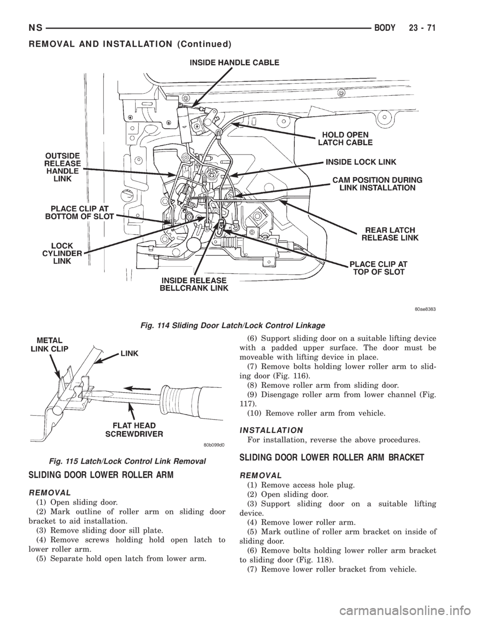
(7) Remove bolts holding lower roller arm to slid-
ing door (Fig. 116).
(8) Remove roller arm from sliding door.
(9) Disengage roller arm from lower channel (Fig.
117).
(10) Remove roller arm from vehicle.
INSTALLATION
For installation, reverse the above procedures.
SLIDING DOOR LOWER ROLLER ARM BRACKET
REMOVAL
(1) Remove access hole plug.
(2) Open sliding door.
(3) Support sliding door on a suitable lifting
device.
(4) Remove lower roller arm.
(5) Mark outline of roller arm bracket on inside of
sliding door.
(6) Remove bolts holding lower roller arm bracket
to sliding door (Fig. 118).
(7) Remove lower roller bracket from vehicle.
Fig. 114 Sliding Door Latch/Lock Control Linkage
Fig. 115 Latch/Lock Control Link Removal
NSBODY 23 - 71
REMOVAL AND INSTALLATION (Continued)