1996 CHRYSLER VOYAGER door lock
[x] Cancel search: door lockPage 1802 of 1938
INSTALLATION
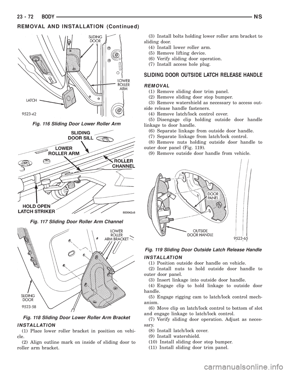
(1) Place lower roller bracket in position on vehi-
cle.
(2) Align outline mark on inside of sliding door to
roller arm bracket.(3) Install bolts holding lower roller arm bracket to
sliding door.
(4) Install lower roller arm.
(5) Remove lifting device.
(6) Verify sliding door operation.
(7) Install access hole plug.
SLIDING DOOR OUTSIDE LATCH RELEASE HANDLE
REMOVAL
(1) Remove sliding door trim panel.
(2) Remove sliding door stop bumper.
(3) Remove watershield as necessary to access out-
side release handle fasteners.
(4) Remove latch/lock control cover.
(5) Disengage clip holding outside door handle
linkage to door handle.
(6) Separate linkage from outside door handle.
(7) Separate linkage from latch/lock control.
(8) Remove nuts holding outside door handle to
outer door panel (Fig. 119).
(9) Remove outside door handle from vehicle.
INSTALLATION
(1) Position outside door handle on vehicle.
(2) Install nuts to hold outside door handle to
outer door panel.
(3) Insert linkage into outside door handle.
(4) Engage clip to hold linkage to outside door
handle.
(5) Engage rigging cam to latch/lock control mech-
anism.
(6) Move clip on latch/lock control to bottom of slot
and engage linkage to latch/lock control.
(7) Verify sliding door operation. Adjust as neces-
sary.
(8) Install latch/lock cover.
(9) Install watershield.
(10) Install sliding door stop bumper.
(11) Install sliding door trim panel.
Fig. 116 Sliding Door Lower Roller Arm
Fig. 117 Sliding Door Roller Arm Channel
Fig. 118 Sliding Door Lower Roller Arm Bracket
Fig. 119 Sliding Door Outside Latch Release Handle
23 - 72 BODYNS
REMOVAL AND INSTALLATION (Continued)
Page 1803 of 1938
SLIDING DOOR REAR LATCH
REMOVAL
(1) Remove sliding door trim panel.
(2) Remove water shield as necessary.
(3) Open sliding door to the ajar position.
(4) Disengage clip holding linkage to rear latch.
(5) Remove screws holding rear latch to sliding
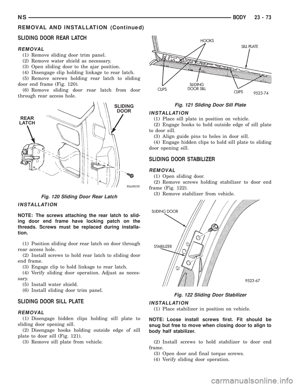
door end frame (Fig. 120).
(6) Remove sliding door rear latch from door
through rear access hole.
INSTALLATION
NOTE: The screws attaching the rear latch to slid-
ing door end frame have locking patch on the
threads. Screws must be replaced during installa-
tion.
(1) Position sliding door rear latch on door through
rear access hole.
(2) Install screws to hold rear latch to sliding door
end frame.
(3) Engage clip to hold linkage to rear latch.
(4) Verify sliding door operation. Adjust as neces-
sary.
(5) Install water shield.
(6) Install sliding door trim panel.
SLIDING DOOR SILL PLATE
REMOVAL
(1) Disengage hidden clips holding sill plate to
sliding door opening sill.
(2) Disengage hooks holding outside edge of sill
plate to door sill (Fig. 121).
(3) Remove sill plate from vehicle.
INSTALLATION
(1) Place sill plate in position on vehicle.
(2) Engage hooks to hold outside edge of sill plate
to door sill.
(3) Align guide pins to holes in door sill.
(4) Engage hidden clips to hold sill plate to sliding
door opening sill.
SLIDING DOOR STABILIZER
REMOVAL
(1) Open sliding door.
(2) Remove screws holding stabilizer to door end
frame (Fig. 122).
(3) Remove stabilizer from vehicle.
INSTALLATION
(1) Place stabilizer in position on vehicle.
NOTE: Loose install screws first. Fit should be
snug but free to move when closing door to align to
body half stabilizer.
(2) Install screws to hold stabilizer to door end
frame.
(3) Open door and final torque screws.
(4) Verify sliding door operation.
Fig. 120 Sliding Door Rear Latch
Fig. 121 Sliding Door Sill Plate
Fig. 122 Sliding Door Stabilizer
NSBODY 23 - 73
REMOVAL AND INSTALLATION (Continued)
Page 1805 of 1938
(5) If necessary, install screw from inside ash
receiver bezel on left sliding door trim panel.
(6) Install sliding door upper frame molding.
SLIDING DOOR UPPER ROLLER
REMOVAL
(1) Open sliding door, do not latch open.
(2) Remove screw holding upper stop bracket to
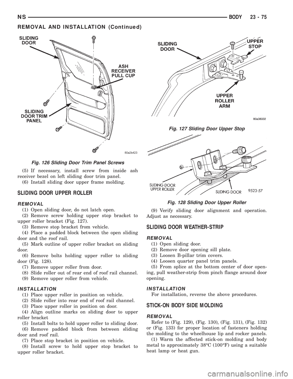
upper roller bracket (Fig. 127).
(3) Remove stop bracket from vehicle.
(4) Place a padded block between the open sliding
door and the roof rail.
(5) Mark outline of upper roller bracket on sliding
door.
(6) Remove bolts holding upper roller to sliding
door (Fig. 128).
(7) Remove upper roller from door.
(8) Slide roller out of rear end of roof rail channel.
(9) Remove upper roller from vehicle.
INSTALLATION
(1) Place upper roller in position on vehicle.
(2) Slide roller into rear end of roof rail channel.
(3) Place upper roller in position on door.
(4) Align outline marks on sliding door to upper
roller bracket
(5) Install bolts to hold upper roller to sliding door.
(6) Remove padded block from between sliding
door and roof rail.
(7) Place stop bracket in position on vehicle.
(8) Install screw to hold upper stop bracket to
upper roller bracket.(9) Verify sliding door alignment and operation.
Adjust as necessary.
SLIDING DOOR WEATHER-STRIP
REMOVAL
(1) Open sliding door.
(2) Remove door opening sill plate.
(3) Loosen B-pillar trim covers.
(4) Loosen quarter panel trim panels.
(5) From splice at the bottom center of door open-
ing, pull weather-strip from pinch flange around door
opening.
INSTALLATION
For installation, reverse the above procedures.
STICK-ON BODY SIDE MOLDING
REMOVAL
Refer to (Fig. 129), (Fig. 130), (Fig. 131), (Fig. 132)
or (Fig. 133) for proper location of fasteners holding
the molding to the wheelhouse lip and rocker panels.
(1) Warm the affected stick-on molding and body
metal to approximately 38ÉC (100ÉF) using a suitable
heat lamp or heat gun.
Fig. 126 Sliding Door Trim Panel Screws
Fig. 127 Sliding Door Upper Stop
Fig. 128 Sliding Door Upper Roller
NSBODY 23 - 75
REMOVAL AND INSTALLATION (Continued)
Page 1810 of 1938
UPPER C-PILLAR TRIM
REMOVAL
(1) Remove quarter trim bolster.
(2) Remove seat belt turning loop from height
adjuster.
(3) Remove screw holding C-pillar trim panel to
C-pillar on right side of SWB vehicle.
(4) Disengage hidden clips holding trim to upper
C-pillar.
(5) Remove upper C-pillar trim from vehicle.
INSTALLATION
(1) Place upper C-pillar trim in position on vehicle.
(2) Engage hidden clips to hold trim to upper
C-pillar.
(3) Install screw to hold C-pillar trim panel to
C-pillar on right side of SWB vehicle.
(4) Install seat belt turning loop onto height
adjuster. Tighten all seat belt bolts to 39 N´m (29 in.
lbs.) torque.
(5) Install quarter trim bolster.
ADJUSTMENTS
SLIDING DOOR ADJUSTMENTS
PRELIMINARY CHECKS
(1) Close sliding door, visually checking C-post
striker alignment entry into latch. Striker at this
point must not affect alignment.(2) On vehicles with left sliding doors, check the
fuel door blocker striker entry into latch. Striker at
this point must not affect alignment.
(3) Check C-post and B-post for door to aperture
gaps and door to door gaps. All gaps should be 5 mm
61 mm.
(4) C
heck door for height using character lines as a
reference. Also check roof contour as a controlling factor.
UP/DOWN ADJUSTMENT
(1) Visually inspect the sliding door for fitting low
at the rear of the door by checking the alignment of
the belt line of the door to quarter panel.
(2) Fully open the sliding door.
(3) Verify that all center hinge bolts are tight.
(4) Adjust the rear of the sliding door up by turn-
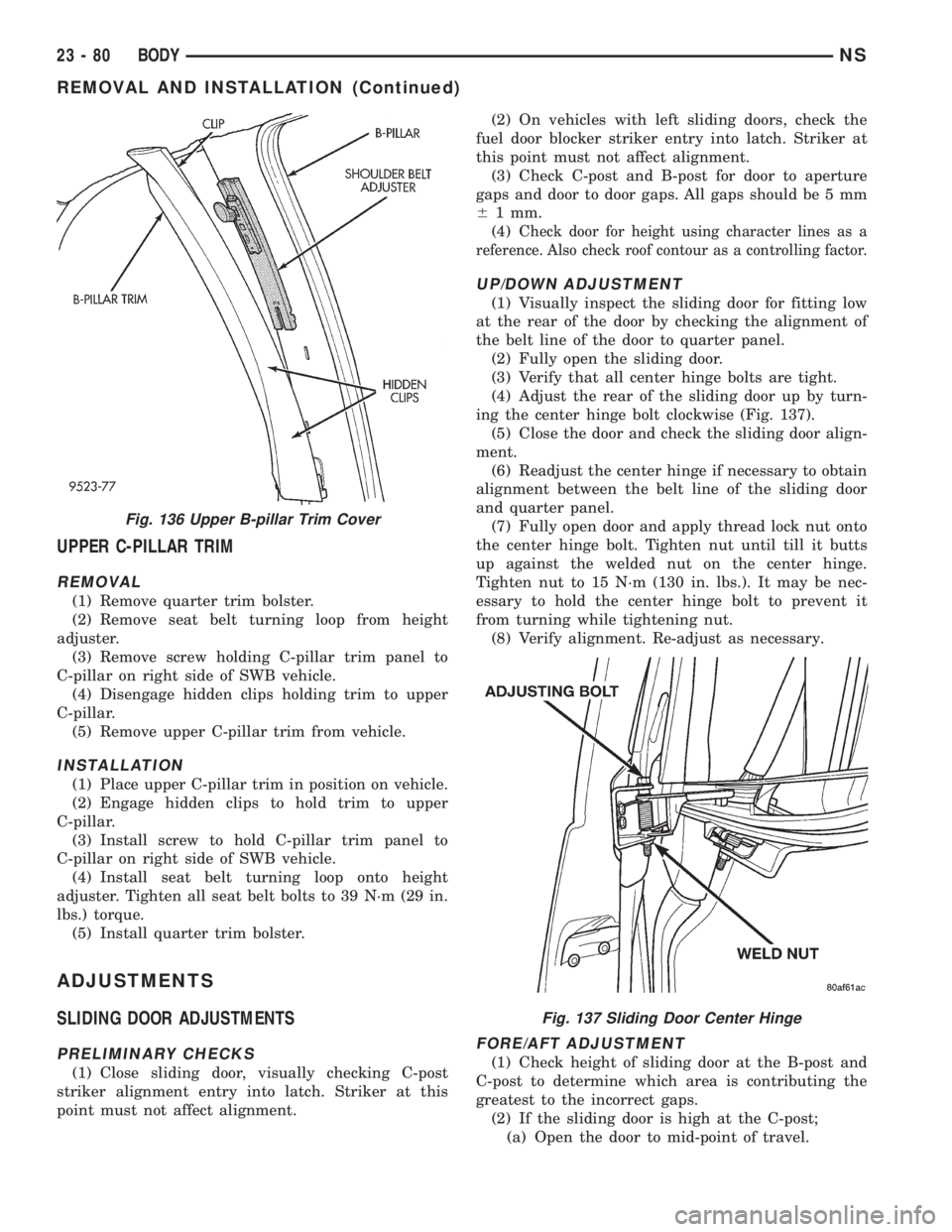
ing the center hinge bolt clockwise (Fig. 137).
(5) Close the door and check the sliding door align-
ment.
(6) Readjust the center hinge if necessary to obtain
alignment between the belt line of the sliding door
and quarter panel.
(7) Fully open door and apply thread lock nut onto
the center hinge bolt. Tighten nut until till it butts
up against the welded nut on the center hinge.
Tighten nut to 15 N´m (130 in. lbs.). It may be nec-
essary to hold the center hinge bolt to prevent it
from turning while tightening nut.
(8) Verify alignment. Re-adjust as necessary.
FORE/AFT ADJUSTMENT
(1) Check height of sliding door at the B-post and
C-post to determine which area is contributing the
greatest to the incorrect gaps.
(2) If the sliding door is high at the C-post;
(a) Open the door to mid-point of travel.
Fig. 136 Upper B-pillar Trim Cover
Fig. 137 Sliding Door Center Hinge
23 - 80 BODYNS
REMOVAL AND INSTALLATION (Continued)
Page 1817 of 1938
HEATING AND AIR CONDITIONING
CONTENTS
page page
FRONT HEATING AND AIR CONDITIONING
SYSTEM............................... 1REAR HEATING AND AIR CONDITIONING
SYSTEM.............................. 41
FRONT HEATING AND AIR CONDITIONING SYSTEM
INDEX
page page
GENERAL INFORMATION
INTRODUCTION......................... 2
SAFETY PRECAUTIONS AND WARNINGS...... 2
DESCRIPTION AND OPERATION
A/C PRESSURE TRANSDUCER.............. 2
A/C SERVICE PORTS..................... 2
AIR DISTRIBUTION DUCTS................. 2
COMPRESSOR HIGH-PRESSURE RELIEF
VALVE................................ 3
CONDENSATE DRAIN..................... 3
ENGINE COOLING SYSTEM REQUIREMENTS . . 3
EVAPORATOR PROBE..................... 3
HANDLING TUBING AND FITTINGS........... 3
HVAC CONTROL MODULE................. 4
REAR BLOWER SPEED SWITCH............ 3
SIDE DOOR HEATER A/C OUTLETS.......... 4
SIDE WINDOW DEMISTER................. 4
SYSTEM AIRFLOW....................... 4
SYSTEM OIL LEVEL...................... 5
DIAGNOSIS AND TESTING
A/C PERFORMANCE TEST................ 12
A/C PRESSURE TRANSDUCER............. 12
ACTUATOR CALIBRATION/DIAGNOSTICS AND
COOLDOWN TEST...................... 6
BLOWER MOTOR AND WHEEL ASSEMBLY.... 13
COMPRESSOR CLUTCH/COIL.............. 13
COMPRESSOR NOISE DIAGNOSIS.......... 13
EXPANSION VALVE...................... 13
HEATER PERFORMANCE TEST............ 15
HVAC CONTROL DIAGNOSTIC CONDITIONS . . . 9
SYSTEM CHARGE LEVEL TEST............ 16SERVICE PROCEDURES
CHARGING REFRIGERANT SYSTEM........ 17
EVACUATING REFRIGERANT SYSTEM....... 18
R-134a REFRIGERANT................... 16
STICKING HVAC CONTROL MODULE PUSH
BUTTONS............................ 19
SYSTEM LEAK CHECKING................ 19
THERMOCOUPLE PROBE................. 19
REMOVAL AND INSTALLATION
A/C PRESSURE TRANSDUCER............. 20
A/C SERVICE PORTS.................... 20
BLEND-AIR DOOR ACTUATOR............. 20
BLOWER MOTOR AND WHEEL ASSEMBLY.... 21
BLOWER MOTOR RESISTOR BLOCK........ 21
BLOWER MOTOR WHEEL................. 22
COMPRESSOR CLUTCH/COIL.............. 23
COMPRESSOR......................... 23
CONDENSER ASSEMBLY................. 25
DISCHARGE LINE....................... 26
EVAPORATOR PROBE.................... 27
EXPANSION VALVE...................... 28
FILTER-DRIER ASSEMBLY................. 28
HEATER A/C UNIT HOUSING............... 29
HEATER CORE......................... 30
HEATER HOSES........................ 31
LIQUID LINE........................... 32
MODE DOOR ACTUATOR................. 32
RECIRC DOOR ACTUATOR................ 34
SIDE WINDOW DEMISTER DUCTS.......... 33
SUCTION LINE.......................... 33
DISASSEMBLY AND ASSEMBLY
HEATER A/C UNIT RECONDITION........... 34
NSHEATING AND AIR CONDITIONING 24 - 1
Page 1831 of 1938
be 21ÉC to 27ÉC (70ÉF to 85ÉF). To test the expansion
valve:
NOTE: Liquid CO2 is required to test the expansion
valve. It is available from most welding supply facil-
ities. CO2 is also available from companies which
service and sell fire extinguishers.
(1) Connect a charging station or manifold gauge
set to the refrigerant system service ports. Verify the
refrigerant charge level.
(2) Close all doors, windows and vents to the pas-
senger compartment.
(3) Set heater A/C control to A/C, full heat,
FLOOR, and high blower.
(4) Start the engine and allow to idle (1000 rpm).
After the engine has reached running temperature,
allow the passenger compartment to heat up. This
will create the need for maximum refrigerant flow
into the evaporator.
(5) If the refrigerant charge is sufficient, discharge
(high pressure) gauge should read 965 to 1655 kPa
(140 to 240 psi). Suction (low pressure) gauge should
read 140 kPa to 207 kPa (20 psi to 30 psig). If system
cannot achieve proper pressure readings, replace the
expansion valve. If pressure is correct, proceed with
test.
WARNING: PROTECT SKIN AND EYES FROM CON-
TACTING CO2 PERSONAL INJURY CAN RESULT.
(6) If suction side low pressure is within specified
range, freeze the expansion valve control head for 30
seconds. Use a super cold substance (liquid CO2).Do
not spray R-134a or R-12 Refrigerant on the
expansion valve for this test.Suction side low
pressure should drop by 10 psi. If not, replace expan-
sion valve.
(7) Allow expansion valve to thaw. The low pres-
sure gauge reading should stabilize at 140 kPa to
240 kPa (20 psi to 30 psig). If not, replace expansion
valve.
(8) When expansion valve test is complete, test
A/C overall performance. Remove all test equipment
before returning vehicle to use.
HEATER PERFORMANCE TEST
PRE-DIAGNOSTIC PREPARATIONS
Review Safety Precautions and Warnings in this
group before performing the following procedures.
Check the coolant level, drive belt tension, vacuum
line connections, radiator air flow and fan operation.
Start engine and allow to warm up to normal tem-
perature.WARNING: DO NOT REMOVE RADIATOR CAP
WHEN ENGINE IS HOT, PERSONAL INJURY CAN
RESULT.
If vehicle has been run recently, wait 15 minutes
before removing cap. Place a rag over the cap and
turn it to the first safety stop. Allow pressure to
escape through the overflow tube. When the system
stabilizes, remove the cap completely.
MAXIMUM HEATER OUTPUT: TEST AND
ACTION
Engine coolant is provided to the heater system by
two 16 mm (5/8 inch inside diameter) heater hoses.
With engine idling at normal running temperature,
set the control to maximum heat, floor, and high
blower setting. Using a test thermometer, check the
air temperature coming from the floor outlets, refer
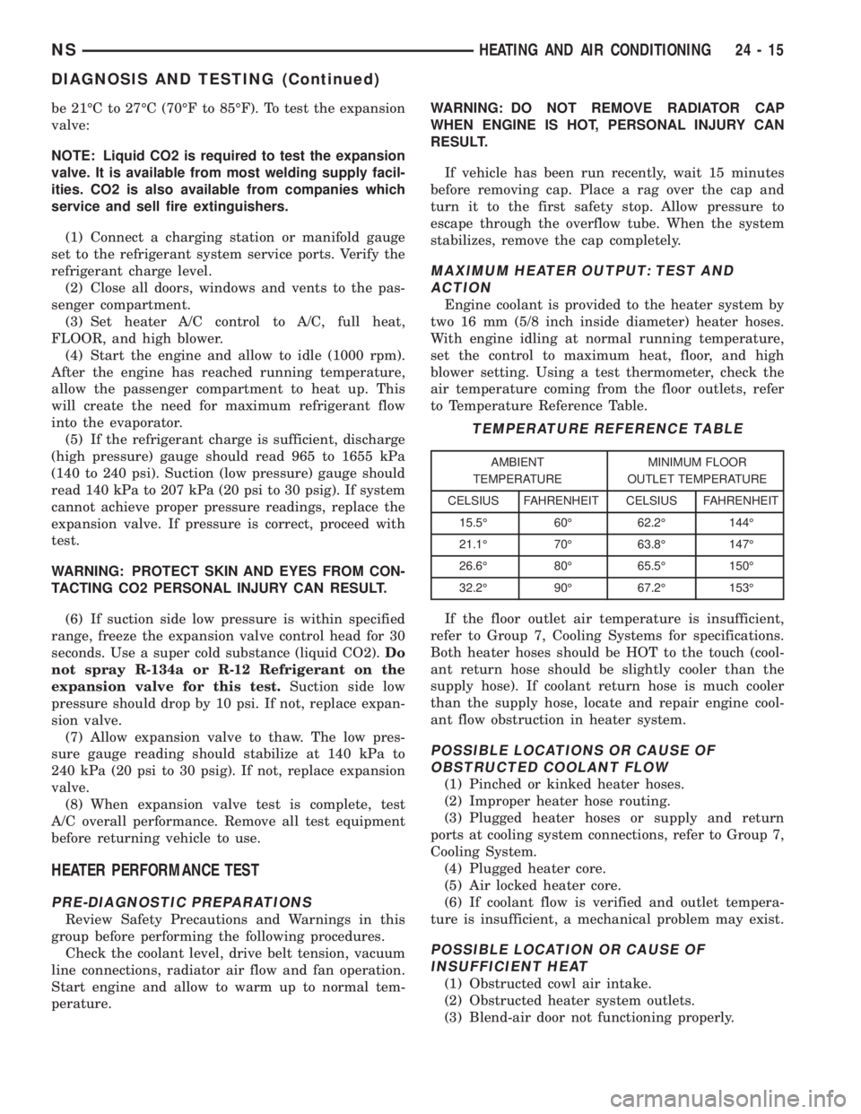
to Temperature Reference Table.
If the floor outlet air temperature is insufficient,
refer to Group 7, Cooling Systems for specifications.
Both heater hoses should be HOT to the touch (cool-
ant return hose should be slightly cooler than the
supply hose). If coolant return hose is much cooler
than the supply hose, locate and repair engine cool-
ant flow obstruction in heater system.
POSSIBLE LOCATIONS OR CAUSE OF
OBSTRUCTED COOLANT FLOW
(1) Pinched or kinked heater hoses.
(2) Improper heater hose routing.
(3) Plugged heater hoses or supply and return
ports at cooling system connections, refer to Group 7,
Cooling System.
(4) Plugged heater core.
(5) Air locked heater core.
(6) If coolant flow is verified and outlet tempera-
ture is insufficient, a mechanical problem may exist.
POSSIBLE LOCATION OR CAUSE OF
INSUFFICIENT HEAT
(1) Obstructed cowl air intake.
(2) Obstructed heater system outlets.
(3) Blend-air door not functioning properly.
TEMPERATURE REFERENCE TABLE
AMBIENT
TEMPERATUREMINIMUM FLOOR
OUTLET TEMPERATURE
CELSIUS FAHRENHEIT CELSIUS FAHRENHEIT
15.5É 60É 62.2É 144É
21.1É 70É 63.8É 147É
26.6É 80É 65.5É 150É
32.2É 90É 67.2É 153É
NSHEATING AND AIR CONDITIONING 24 - 15
DIAGNOSIS AND TESTING (Continued)
Page 1857 of 1938
REAR HEATING AND AIR CONDITIONING SYSTEM
INDEX
page page
GENERAL INFORMATION
INTRODUCTION......................... 41
DESCRIPTION AND OPERATION
REAR BLOWER RESISTOR BLOCK.......... 41
REAR HEATER AND A/C LINES............. 41
SYSTEM OPERATION.................... 41
DIAGNOSIS AND TESTING
DIAGNOSTIC PROCEDURES............... 43
REMOVAL AND INSTALLATION
AIR DISTRIBUTION DUCT-A/C.............. 43
AIR DISTRIBUTION DUCT-HEATER.......... 43
EVAPORATOR AND EXPANSION VALVE...... 44MODE DOOR ACTUATOR................. 49
MODE DOOR........................... 49
REAR AIR CONDITIONING LINES........... 45
REAR HEATER A/C AIR OUTLETS........... 45
REAR HEATER A/C BLOWER MOTOR........ 46
REAR HEATER A/C UNIT.................. 46
REAR HEATER CORE.................... 48
REAR HEATER LINES.................... 49
REAR HEATER-A/C AUXILIARY CONDENSER . . 45
REAR HEATER-A/C CONTROL ILLUMINATION
BULB............................... 46
GENERAL INFORMATION
INTRODUCTION
For proper operation of the rear heating A/C sys-
tem, refer to Owner's Manual supplied with the vehi-
cle.
DESCRIPTION AND OPERATION
REAR BLOWER RESISTOR BLOCK
The rear blower motor resistor is not serviceable
separately. The resistor is integral to the blower
motor. If resistor is faulty, it is necessary to replace
the complete blower motor.
REAR HEATER AND A/C LINES
The rear heater and A/C lines are all serviced as
individual pieces. When disconnecting any line orblock ensure that the area around it is clean of any
contaminations that can get in to the system (Fig. 1),
(Fig. 2), (Fig. 4), (Fig. 3) and (Fig. 5).
SYSTEM OPERATION
The auxiliary rear heating-air/conditioning unit is
located in the right rear quarter panel. The rear
heater A/C control operates in conjunction with the
front heater A/C control. A four position two speed
blower (override) switch is located on the front
Heater A/C control panel (Fig. 6). The operator can
use the rear heater A/C blower switch to operate the
blower, regardless of the rear control setting. In the
OFF position, the rear control will not function. In
the ON (RR) position, the rear control will function
normally providing three speeds (Fig. 7). The mode
setting is controlled by the front A/C control panel.
Fig. 1 Rear Heater and A/C Lines
NSHEATING AND AIR CONDITIONING 24 - 41
Page 1867 of 1938
HEATING AND AIR CONDITIONING
CONTENTS
page page
GENERAL INFORMATION
INTRODUCTION........................ 1
SAFETY PRECAUTIONS AND WARNINGS.... 2
DESCRIPTION AND OPERATION
A/C PRESSURE TRANSDUCER............ 2
A/C SERVICE PORTS.................... 2
AIR DISTRIBUTION DUCTS............... 2
COMPRESSOR......................... 2
COMPRESSOR HIGH-PRESSURE RELIEF
VALVE .............................. 3
CONDENSATE DRAIN.................... 3
ENGINE COOLING SYSTEM REQUIREMENTS . 3
EVAPORATOR PROBE................... 3
HANDLING TUBING AND FITTINGS........ 3
HVAC CONTROL MODULE................ 3
SIDE DOOR HEATER A/C OUTLETS........ 4
SIDE WINDOW DEMISTER............... 4
SYSTEM AIRFLOW..................... 4
SYSTEM OIL LEVEL..................... 4
DIAGNOSIS AND TESTING
A/C PERFORMANCE TEST............... 11
A/C PRESSURE TRANSDUCER........... 11
ACTUATOR CALIBRATION/DIAGNOSTICS AND
COOLDOWN TEST..................... 5
BLOWER MOTOR AND WHEEL ASSEMBLY . 12
COMPRESSOR CLUTCH/COIL............ 12
COMPRESSOR NOISE DIAGNOSIS........ 12
EXPANSION VALVE.................... 14
HEATER PERFORMANCE TEST........... 14
HVAC CONTROL DIAGNOSTIC CONDITIONS . 9
SYSTEM CHARGE LEVEL TEST........... 15SERVICE PROCEDURES
CHARGING REFRIGERANT SYSTEM....... 17
EVACUATING REFRIGERANT SYSTEM..... 17
R-134a REFRIGERANT.................. 16
STICKING HVAC CONTROL MODULE PUSH
BUTTONS.......................... 18
SYSTEM LEAK CHECKING............... 19
THERMOCOUPLE PROBE............... 18
REMOVAL AND INSTALLATION
A/C PRESSURE TRANSDUCER........... 19
A/C SERVICE PORTS................... 19
BLEND-AIR DOOR ACTUATOR........... 20
BLOWER MOTOR AND WHEEL ASSEMBLY . 20
BLOWER MOTOR RESISTOR BLOCK...... 21
BLOWER MOTOR WHEEL............... 22
COMPRESSOR (2.5L TURBO DIESEL)..... 22
CONDENSER ASSEMBLY................ 23
DISCHARGE LINE..................... 23
EVAPORATOR PROBE.................. 24
EXPANSION VALVE.................... 25
FILTER-DRIER ASSEMBLY............... 26
HEATER A/C UNIT HOUSING............. 26
HEATER CORE........................ 26
HEATER HOSES....................... 28
LIQUID LINE......................... 28
MODE DOOR ACTUATOR................ 29
RECIRC DOOR ACTUATOR.............. 30
SIDE WINDOW DEMISTER DUCTS........ 29
SUCTION LINE........................ 29
DISASSEMBLY AND ASSEMBLY
HEATER A/C UNIT RECONDITION......... 30
GENERAL INFORMATION
INTRODUCTION
The Heater, or Heater and Air Conditioning sys-
tems share many of the same components. This
group will deal with both systems together when
component function is common, and separately when
they are not.
For proper operation of the instrument panel con-
trols, refer to the Owner's Manual provided with the
vehicle.All vehicles are equipped with a common Heater
A/C unit housing assembly. When the vehicle has
only a heater system, the evaporator and recirculat-
ing air door are omitted.
An optional zone control HVAC unit is available.
This unit has dual blend-air doors that can be regu-
lated independently of each other. The temperature
setting can be different from driver's side to passen-
ger side.
NS/GSHEATING AND AIR CONDITIONING 24 - 1