1996 CHRYSLER VOYAGER door lock
[x] Cancel search: door lockPage 1752 of 1938
BODY COMPONENT SERVICE
INDEX
page page
DIAGNOSIS AND TESTING
WATER LEAKS.......................... 23
WIND NOISE........................... 24
SERVICE PROCEDURES
HEAT STAKING......................... 24
REMOVAL AND INSTALLATION
A-PILLAR LOWER EXTENSION TRIM........ 25
A-PILLAR TRIM PANEL................... 25
COWL COVER.......................... 25
COWL TRIM............................ 25
FLOOR CARPET........................ 26
FRONT DOOR APPLIQUE................. 28
FRONT DOOR CHECK STRAP.............. 28
FRONT DOOR FRAME CLOSEOUT MOLDINGS . 29
FRONT DOOR GLASS RUN WEATHER-STRIP . . 30
FRONT DOOR GLASS.................... 29
FRONT DOOR HINGE.................... 30
FRONT DOOR INNER BELT MOLDING....... 31
FRONT DOOR LATCH STRIKER............ 32
FRONT DOOR LATCH.................... 31
FRONT DOOR LOCK CYLINDER............ 32
FRONT DOOR OUTER BELT MOLDING....... 33
FRONT DOOR OUTSIDE HANDLE........... 33
FRONT DOOR REFLECTOR............... 34
FRONT DOOR SILL PLATE................ 34
FRONT DOOR TRIM PANEL................ 34
FRONT DOOR WEATHER-STRIP............ 36
FRONT DOOR WINDOW CRANK............ 36
FRONT DOOR WINDOW REGULATOR....... 36
FRONT DOOR.......................... 27
FRONT SEAT........................... 37
FRONT WHEELHOUSE SPLASH SHIELD..... 37
FUEL FILL DOOR BLOCKER LATCH STRIKER . . 38
FUEL FILL DOOR BLOCKER LATCH......... 38
FUEL FILL DOOR BLOCKER LOCKOUT LINK . . 38
FUEL FILLER HOUSING ± WITH BLOCKER
LATCH .............................. 39
GRILLE............................... 39
HEADLINING........................... 39
HOOD HINGE.......................... 41
HOOD LATCH STRIKER................... 42
HOOD LATCH.......................... 41
HOOD RELEASE CABLE.................. 42
HOOD RELEASE HANDLE................. 42
HOOD................................ 40
JACK STORAGE COVER.................. 43
LEFT D-PILLAR TRIM PANEL............... 43
LEFT QUARTER TRIM PANEL.............. 44
LIFTGATE CHMSL ACCESS PANEL.......... 47
LIFTGATE HINGE........................ 47LIFTGATE LATCH STRIKER................ 47
LIFTGATE LATCH........................ 47
LIFTGATE LOCK CYLINDER............... 48
LIFTGATE OUTSIDE HANDLE.............. 48
LIFTGATE PROP ASSEMBLY............... 49
LIFTGATE SILL PLATE.................... 49
LIFTGATE STABILIZER WEDGE STRIKER..... 49
LIFTGATE STABILIZER WEDGE............. 49
LIFTGATE TRIM PANEL................... 50
LIFTGATE UPPER FRAME MOLDING........ 50
LIFTGATE UPPER FRAME SIDE MOLDINGS . . . 51
LIFTGATE............................. 46
LOWER B-PILLAR TRIM COVER............ 51
LUGGAGE RACK CROSSBAR.............. 51
LUGGAGE RACK RISER COVER............ 52
LUGGAGE RACK SIDE RAIL............... 52
OVERHEAD GRAB-HANDLES.............. 52
QUARTER GLASS....................... 52
QUARTER TRIM BOLSTER................ 53
RADIATOR CLOSURE PANEL CROSSMEMBER . 53
RAIL LAMP MODULE..................... 54
REAR HEADER TRIM..................... 55
REAR HVAC LOUVER AND BEZEL.......... 55
RIGHT D-PILLAR TRIM PANEL.............. 55
RIGHT QUARTER TRIM PANEL............. 56
ROOF APERTURE (RAP) MOLDING.......... 57
SEAT BELT BUCKLE FIRST REAR QUAD
BUCKET............................. 58
SEAT BELT BUCKLE FIRST REAR ± TWO
PASSENGER BENCH................... 58
SEAT BELT BUCKLE SECOND REAR ± THREE
PASSENGER BENCH................... 59
SEAT BELT BUCKLE ± FRONT INBOARD..... 57
SEAT BELT FIRST REAR ANCHOR BRACKET ±
LWB ................................ 59
SEAT BELT FIRST REAR OUTBOARD ± LWB
FOUR DOOR.......................... 60
SEAT BELT FIRST REAR OUTBOARD ± SWB
FOUR DOOR.......................... 60
SEAT BELT LEFT FIRST REAR OUTBOARD ±
LWB THREE DOOR..................... 61
SEAT BELT LEFT FIRST REAR OUTBOARD ±
SWB THREE DOOR.................... 61
SEAT BELT SECOND REAR OUTBOARD ±
SWB ................................ 61
SEAT BELT SECOND RIGHT REAR OUTBOARD
±LWB ............................... 62
SEAT BELT ± OUTBOARD FRONT........... 59
SECOND RIGHT REAR OUTBOARD SEAT BELT
± LWB W/REAR HVAC................... 62
23 - 22 BODYNS
Page 1753 of 1938
SHOULDER BELT HEIGHT ADJUSTER KNOB . . 64
SHOULDER BELT HEIGHT ADJUSTER±BOR
C-PILLAR............................ 64
SIDE VIEW MIRROR..................... 64
SLIDING DOOR CENTER HINGE............ 66
SLIDING DOOR CENTER STOP TRIM COVER . . 66
SLIDING DOOR CENTER STRIKER ASSEMBLY . 67
SLIDING DOOR HOLD OPEN LATCH STRIKER . 67
SLIDING DOOR HOLD OPEN LATCH......... 67
SLIDING DOOR INSIDE LATCH HANDLE
BELLCRANK.......................... 68
SLIDING DOOR INSIDE LATCH HANDLE...... 68
SLIDING DOOR INSIDE LATCH RELEASE
MECHANISM.......................... 69
SLIDING DOOR LATCH STRIKER........... 69
SLIDING DOOR LATCH/LOCK CONTROL..... 70
SLIDING DOOR LOWER ROLLER ARM
BRACKET............................ 71
SLIDING DOOR LOWER ROLLER ARM....... 71SLIDING DOOR OUTSIDE LATCH RELEASE
HANDLE............................. 72
SLIDING DOOR REAR LATCH.............. 73
SLIDING DOOR SILL PLATE............... 73
SLIDING DOOR STABILIZER SOCKET........ 74
SLIDING DOOR STABILIZER............... 73
SLIDING DOOR STOP BUMPER............ 74
SLIDING DOOR TRIM PANEL............... 74
SLIDING DOOR UPPER ROLLER............ 75
SLIDING DOOR WEATHER-STRIP........... 75
SLIDING DOOR......................... 64
STICK-ON BODY SIDE MOLDING........... 75
SUN VISOR SUPPORT................... 78
SUN VISOR............................ 76
UPPER B-PILLAR TRIM COVER............. 78
UPPER C-PILLAR TRIM................... 80
ADJUSTMENTS
SLIDING DOOR ADJUSTMENTS............ 80
DIAGNOSIS AND TESTING
WATER LEAKS
Water leaks can be caused by poor sealing,
improper body component alignment, body seam
porosity, missing plugs, or blocked drain holes. Cen-
trifugal and gravitational force can cause water to
drip from a location away from the actual leak point,
making leak detection difficult. All body sealing
points should be water tight in normal wet-driving
conditions. Water flowing downward from the front of
the vehicle should not enter the passenger or luggage
compartment. Moving sealing surfaces will not
always seal water tight under all conditions. At
times, side glass or door seals will allow water to
enter the passenger compartment during high pres-
sure washing or hard driving rain (severe) condi-
tions. Overcompensating on door or glass
adjustments to stop a water leak that occurs under
severe conditions can cause premature seal wear and
excessive closing or latching effort. After completing
a repair, water-test vehicle to verify leak has stopped
before returning vehicle to use.
VISUAL INSPECTION BEFORE WATER LEAK
TESTS
Verify that floor and body plugs are in place, body
drains are clear, and body components are properly
aligned and sealed. If component alignment or seal-
ing is necessary, refer to the appropriate section of
this group for proper procedures.
WATER LEAK TESTS
WARNING: DO NOT USE ELECTRIC SHOP LIGHTS
OR TOOLS IN WATER TEST AREA. PERSONAL
INJURY CAN RESULT.When the conditions causing a water leak have
been determined, simulate the conditions as closely
as possible.
²If a leak occurs with the vehicle parked in a
steady light rain, flood the leak area with an open-
ended garden hose.
²If a leak occurs while driving at highway speeds
in a steady rain, test the leak area with a reasonable
velocity stream or fan spray of water. Direct the
spray in a direction comparable to actual conditions.
²If a leak occurs when the vehicle is parked on an
incline, hoist the end or side of the vehicle to simu-
late this condition. This method can be used when
the leak occurs when the vehicle accelerates, stops or
turns. If the leak occurs on acceleration, hoist the
front of the vehicle. If the leak occurs when braking,
hoist the back of the vehicle. If the leak occurs on left
turns, hoist the left side of the vehicle. If the leak
occurs on right turns, hoist the right side of the vehi-
cle. For hoisting recommendations refer to Group 0,
Lubrication and Maintenance, General Information
section.
WATER LEAK DETECTION
To detect a water leak point-of-entry, do a water
test and watch for water tracks or droplets forming
on the inside of the vehicle. If necessary, remove inte-
rior trim covers or panels to gain visual access to the
leak area. If the hose cannot be positioned without
being held, have someone help do the water test.
NSBODY 23 - 23
Page 1757 of 1938
CAUTION: Ensure that the correct fasteners are
installed in the proper locations. Damage to the fuel
tank may result.
(5) Install floor escutcheons.
(6) Install Quarter trim panels.
(7) Install D-pillar trim covers.
(8) Install lower B-pillar trim covers.
(9) Install rear door sill plate.
(10) Install sliding door sill plates.
(11) Install front cowl panels and sill plates.
(12) Install second rear seat.
(13) Install first rear seat.
(14) Install front center console.
(15) Install front seats.
FRONT DOOR
CAUTION: If the hinge pin must be removed from
the hinge, do not reuse the original pin. The struc-
tural integrity of the hinge would be reduced. Verify
availability prior to proceeding if hinge pins are to
be removed.
NOTE: The retaining clips used on the door hinge
pins are not to be re-used. Verify availability prior to
proceeding if clips are to be removed.
REMOVAL
(1) Open front door.
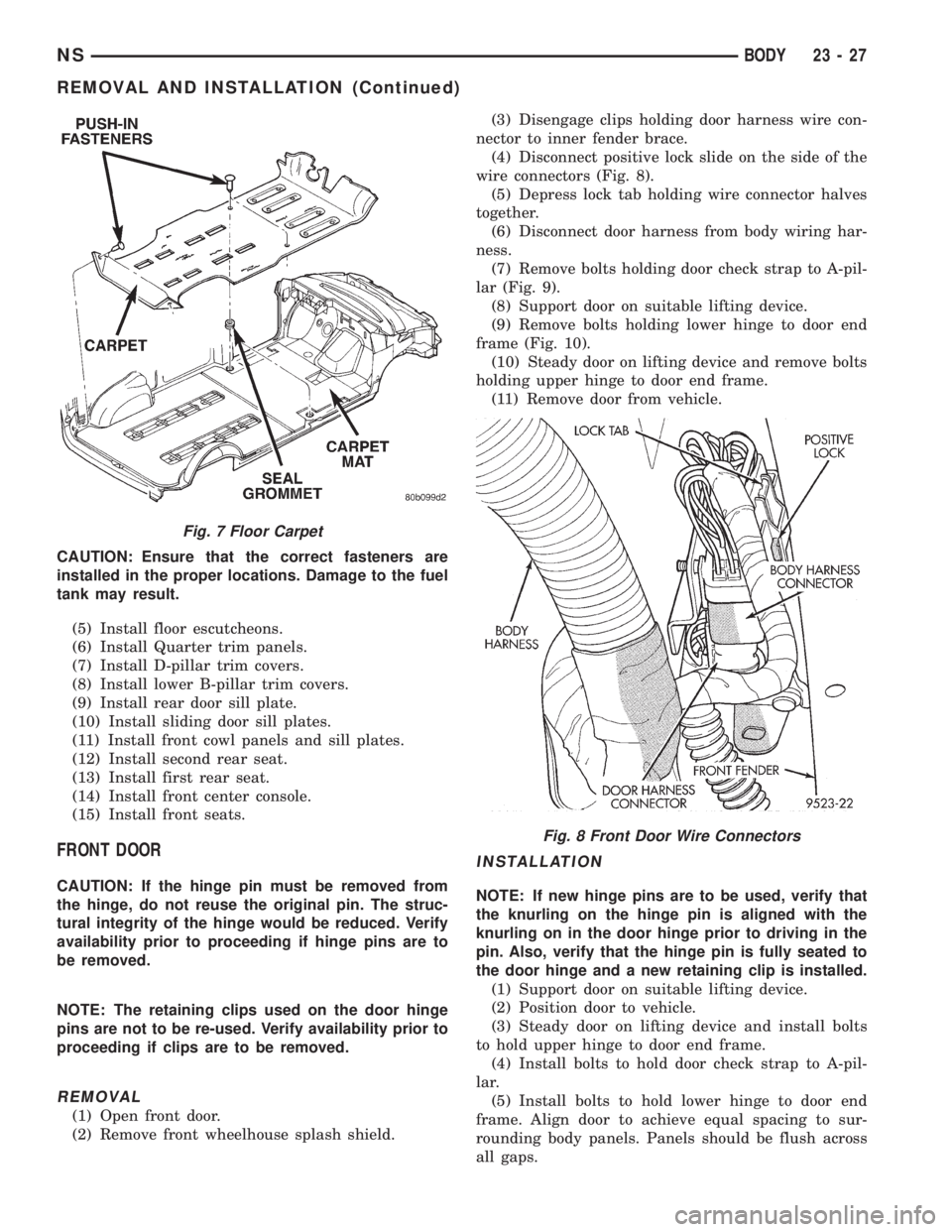
(2) Remove front wheelhouse splash shield.(3) Disengage clips holding door harness wire con-
nector to inner fender brace.
(4) Disconnect positive lock slide on the side of the
wire connectors (Fig. 8).
(5) Depress lock tab holding wire connector halves
together.
(6) Disconnect door harness from body wiring har-
ness.
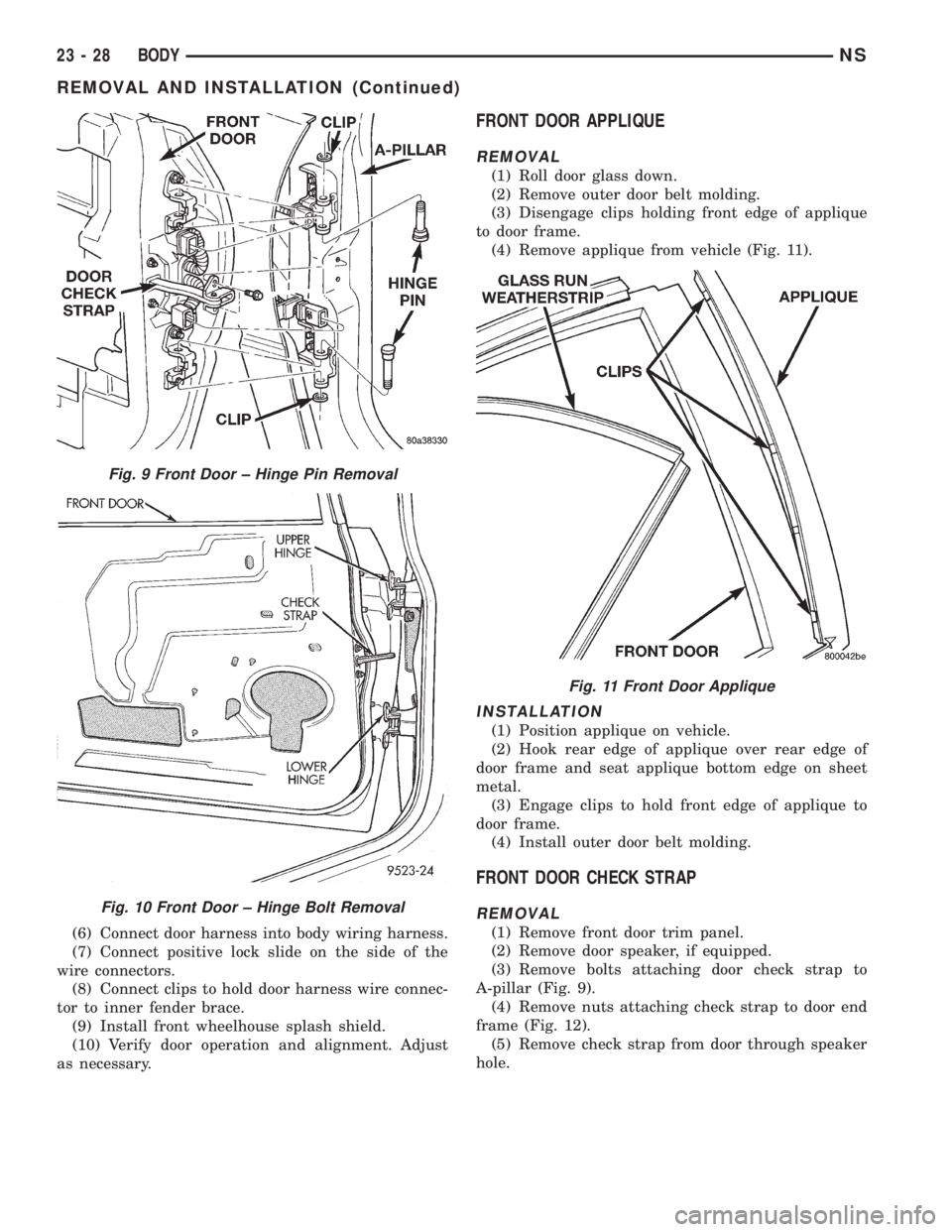
(7) Remove bolts holding door check strap to A-pil-
lar (Fig. 9).
(8) Support door on suitable lifting device.
(9) Remove bolts holding lower hinge to door end
frame (Fig. 10).
(10) Steady door on lifting device and remove bolts
holding upper hinge to door end frame.
(11) Remove door from vehicle.
INSTALLATION
NOTE: If new hinge pins are to be used, verify that
the knurling on the hinge pin is aligned with the
knurling on in the door hinge prior to driving in the
pin. Also, verify that the hinge pin is fully seated to
the door hinge and a new retaining clip is installed.
(1) Support door on suitable lifting device.
(2) Position door to vehicle.
(3) Steady door on lifting device and install bolts
to hold upper hinge to door end frame.
(4) Install bolts to hold door check strap to A-pil-
lar.
(5) Install bolts to hold lower hinge to door end
frame. Align door to achieve equal spacing to sur-
rounding body panels. Panels should be flush across
all gaps.
Fig. 7 Floor Carpet
Fig. 8 Front Door Wire Connectors
NSBODY 23 - 27
REMOVAL AND INSTALLATION (Continued)
Page 1758 of 1938
(6) Connect door harness into body wiring harness.
(7) Connect positive lock slide on the side of the
wire connectors.
(8) Connect clips to hold door harness wire connec-
tor to inner fender brace.
(9) Install front wheelhouse splash shield.
(10) Verify door operation and alignment. Adjust
as necessary.
FRONT DOOR APPLIQUE
REMOVAL
(1) Roll door glass down.
(2) Remove outer door belt molding.
(3) Disengage clips holding front edge of applique
to door frame.
(4) Remove applique from vehicle (Fig. 11).
INSTALLATION
(1) Position applique on vehicle.
(2) Hook rear edge of applique over rear edge of
door frame and seat applique bottom edge on sheet
metal.
(3) Engage clips to hold front edge of applique to
door frame.
(4) Install outer door belt molding.
FRONT DOOR CHECK STRAP
REMOVAL
(1) Remove front door trim panel.
(2) Remove door speaker, if equipped.
(3) Remove bolts attaching door check strap to
A-pillar (Fig. 9).
(4) Remove nuts attaching check strap to door end
frame (Fig. 12).
(5) Remove check strap from door through speaker
hole.
Fig. 9 Front Door ± Hinge Pin Removal
Fig. 10 Front Door ± Hinge Bolt Removal
Fig. 11 Front Door Applique
23 - 28 BODYNS
REMOVAL AND INSTALLATION (Continued)
Page 1761 of 1938
NOTE: If both hinges on one door are to be
replaced, remove and install one hinge completely
prior to beginning the second hinge.
REMOVAL
(1) Release front door latch and open door.
(2) Support door on suitable lifting device.
(3) Remove bolts holding front door to door hinge.
(4) Remove bolts holding hinge to pillar.
(5) Remove door hinge from vehicle.
INSTALLATION
CAUTION: When installing a new hinge, make sure
that the head of each hinge pin is fully seated into
the door hinge. Also, remove the plastic shipping
clip and replace it with the correct metal retaining
clip once the hinge pin is seated.
(1) Paint hinge prior to installation, if necessary.
(2) Position door hinge on vehicle.
(3) Install bolts to hold hinge to pillar.
(4) Install bolts to hold front door to door hinge.
(5) Align door to achieve equal spacing to sur-
rounding body panels. Panels should be flush across
all gaps.
(6) Verify door alignment and operation. Adjust as
necessary.
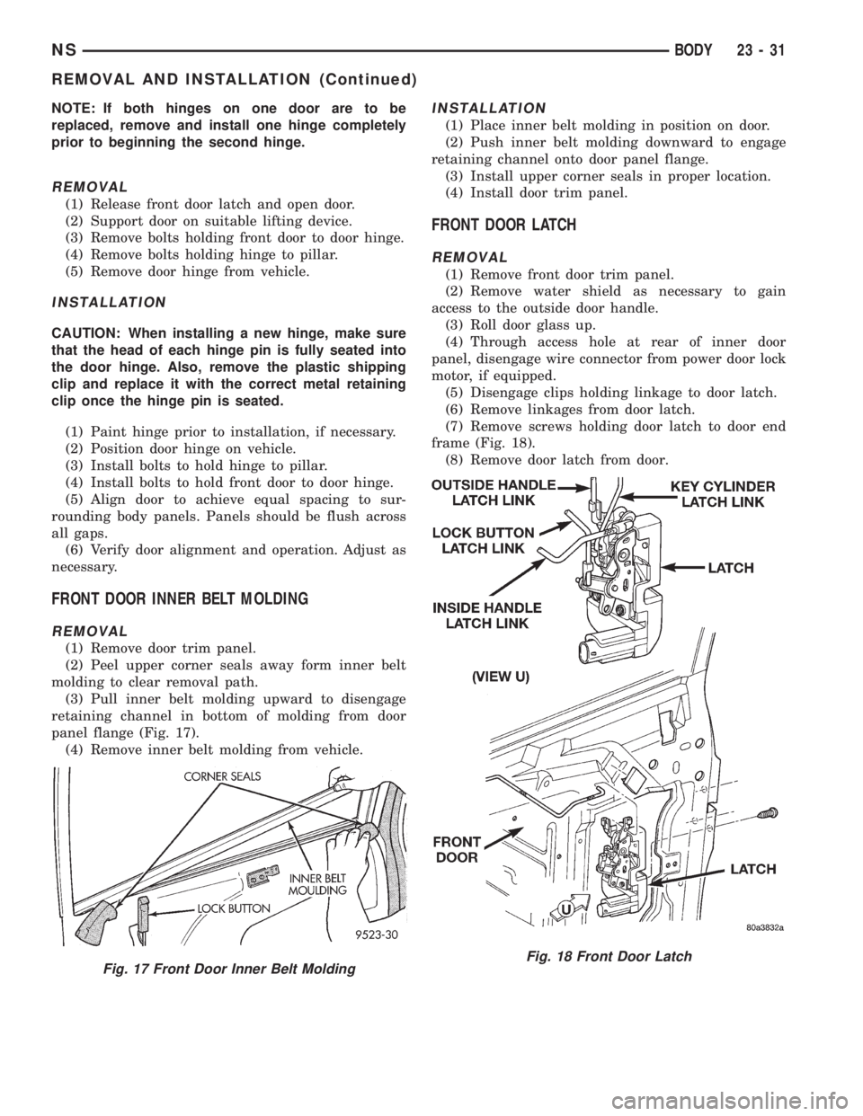
FRONT DOOR INNER BELT MOLDING
REMOVAL
(1) Remove door trim panel.
(2) Peel upper corner seals away form inner belt
molding to clear removal path.
(3) Pull inner belt molding upward to disengage
retaining channel in bottom of molding from door
panel flange (Fig. 17).
(4) Remove inner belt molding from vehicle.
INSTALLATION
(1) Place inner belt molding in position on door.
(2) Push inner belt molding downward to engage
retaining channel onto door panel flange.
(3) Install upper corner seals in proper location.
(4) Install door trim panel.
FRONT DOOR LATCH
REMOVAL
(1) Remove front door trim panel.
(2) Remove water shield as necessary to gain
access to the outside door handle.
(3) Roll door glass up.
(4) Through access hole at rear of inner door
panel, disengage wire connector from power door lock
motor, if equipped.
(5) Disengage clips holding linkage to door latch.
(6) Remove linkages from door latch.
(7) Remove screws holding door latch to door end
frame (Fig. 18).
(8) Remove door latch from door.
Fig. 17 Front Door Inner Belt MoldingFig. 18 Front Door Latch
NSBODY 23 - 31
REMOVAL AND INSTALLATION (Continued)
Page 1762 of 1938
INSTALLATION
NOTE: The screws attaching the door latch to the
door end frame have nylon patches on the threads.
All screws must be replaced when the latch has
been removed.
(1) Place door latch in position on door end frame.
(2) Install screws to hold door latch to door end
frame.
(3) Insert linkage into door latch.
(4) Engage clips to hold linkage to door latch.
(5) Connect wire connector into power door lock
motor, if equipped.
(6) Insert a hex wrench through the elongated hole
located in the door shut face above the latch.
(7) Loosen allen head screw.
(8) Pull outward on the outside door handle and
release.
(9) Tighten allen head screw.
(10) Verify door latch and power door lock opera-
tion.
(11) Install water shield and front door trim panel.
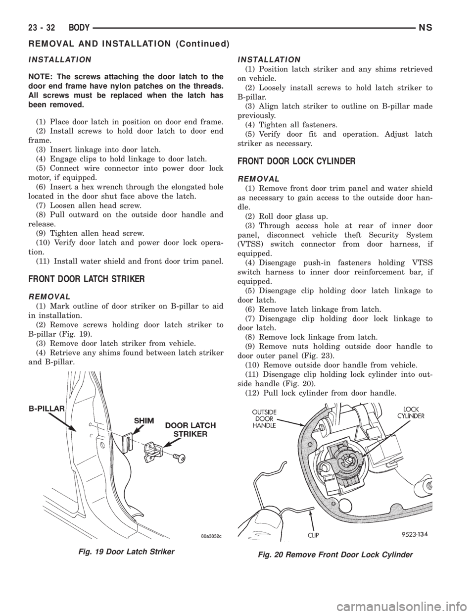
FRONT DOOR LATCH STRIKER
REMOVAL
(1) Mark outline of door striker on B-pillar to aid
in installation.
(2) Remove screws holding door latch striker to
B-pillar (Fig. 19).
(3) Remove door latch striker from vehicle.
(4) Retrieve any shims found between latch striker
and B-pillar.
INSTALLATION
(1) Position latch striker and any shims retrieved
on vehicle.
(2) Loosely install screws to hold latch striker to
B-pillar.
(3) Align latch striker to outline on B-pillar made
previously.
(4) Tighten all fasteners.
(5) Verify door fit and operation. Adjust latch
striker as necessary.
FRONT DOOR LOCK CYLINDER
REMOVAL
(1) Remove front door trim panel and water shield
as necessary to gain access to the outside door han-
dle.
(2) Roll door glass up.
(3) Through access hole at rear of inner door
panel, disconnect vehicle theft Security System
(VTSS) switch connector from door harness, if
equipped.
(4) Disengage push-in fasteners holding VTSS
switch harness to inner door reinforcement bar, if
equipped.
(5) Disengage clip holding door latch linkage to
door latch.
(6) Remove latch linkage from latch.
(7) Disengage clip holding door lock linkage to
door latch.
(8) Remove lock linkage from latch.
(9) Remove nuts holding outside door handle to
door outer panel (Fig. 23).
(10) Remove outside door handle from vehicle.
(11) Disengage clip holding lock cylinder into out-
side handle (Fig. 20).
(12) Pull lock cylinder from door handle.
Fig. 19 Door Latch StrikerFig. 20 Remove Front Door Lock Cylinder
23 - 32 BODYNS
REMOVAL AND INSTALLATION (Continued)
Page 1763 of 1938
INSTALLATION
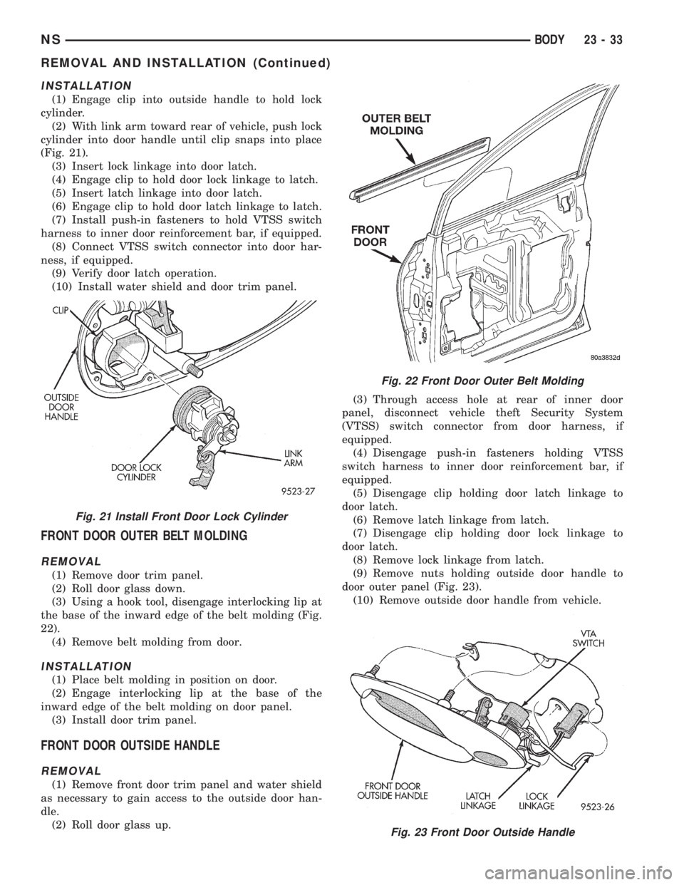
(1) Engage clip into outside handle to hold lock
cylinder.
(2) With link arm toward rear of vehicle, push lock
cylinder into door handle until clip snaps into place
(Fig. 21).
(3) Insert lock linkage into door latch.
(4) Engage clip to hold door lock linkage to latch.
(5) Insert latch linkage into door latch.
(6) Engage clip to hold door latch linkage to latch.
(7) Install push-in fasteners to hold VTSS switch
harness to inner door reinforcement bar, if equipped.
(8) Connect VTSS switch connector into door har-
ness, if equipped.
(9) Verify door latch operation.
(10) Install water shield and door trim panel.
FRONT DOOR OUTER BELT MOLDING
REMOVAL
(1) Remove door trim panel.
(2) Roll door glass down.
(3) Using a hook tool, disengage interlocking lip at
the base of the inward edge of the belt molding (Fig.
22).
(4) Remove belt molding from door.
INSTALLATION
(1) Place belt molding in position on door.
(2) Engage interlocking lip at the base of the
inward edge of the belt molding on door panel.
(3) Install door trim panel.
FRONT DOOR OUTSIDE HANDLE
REMOVAL
(1) Remove front door trim panel and water shield
as necessary to gain access to the outside door han-
dle.
(2) Roll door glass up.(3) Through access hole at rear of inner door
panel, disconnect vehicle theft Security System
(VTSS) switch connector from door harness, if
equipped.
(4) Disengage push-in fasteners holding VTSS
switch harness to inner door reinforcement bar, if
equipped.
(5) Disengage clip holding door latch linkage to
door latch.
(6) Remove latch linkage from latch.
(7) Disengage clip holding door lock linkage to
door latch.
(8) Remove lock linkage from latch.
(9) Remove nuts holding outside door handle to
door outer panel (Fig. 23).
(10) Remove outside door handle from vehicle.
Fig. 21 Install Front Door Lock Cylinder
Fig. 22 Front Door Outer Belt Molding
Fig. 23 Front Door Outside Handle
NSBODY 23 - 33
REMOVAL AND INSTALLATION (Continued)
Page 1764 of 1938
INSTALLATION
If outside door handle replacement is necessary,
transfer lock cylinder from the original handle to the
new one.
(1) Place outside door handle in position on vehi-
cle.
(2) Install nuts to hold outside door handle to door
outer panel (Fig. 23).
(3) Insert lock linkage into door latch.
(4) Engage clip to hold door lock linkage to latch.
(5) Insert latch linkage into door latch.
(6) Engage clip to hold door latch linkage to latch.
(7) Install push-in fasteners to hold VTSS switch
harness to inner door reinforcement bar, if equipped.
(8) Connect VTSS switch connector into door har-
ness, if equipped.
(9) Verify door latch operation.
(10) Install water shield and door trim panel.
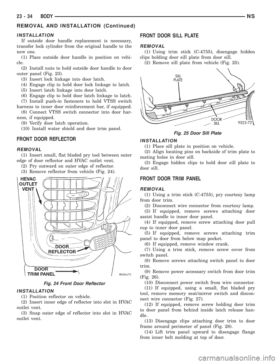
FRONT DOOR REFLECTOR
REMOVAL
(1) Insert small, flat bladed pry tool between outer
edge of door reflector and HVAC outlet vent.
(2) Pry outward on outer edge of reflector.
(3) Remove reflector from vehicle (Fig. 24).
INSTALLATION
(1) Position reflector on vehicle.
(2) Insert inner edge of reflector into slot in HVAC
outlet vent.
(3) Snap outer edge of reflector into slot in HVAC
outlet vent.
FRONT DOOR SILL PLATE
REMOVAL
(1) Using trim stick (C-4755), disengage hidden
clips holding door sill plate from door sill.
(2) Remove sill plate from vehicle (Fig. 25).
INSTALLATION
(1) Place sill plate in position on vehicle.
(2) Align locating pins on backside of trim plate to
mating holes in door sill.
(3) Engage hidden clips to hold door sill plate to
door sill.
FRONT DOOR TRIM PANEL
REMOVAL
(1) Using a trim stick (C-4755), pry courtesy lamp
from door trim.
(2) Disconnect wire connector from courtesy lamp.
(3) If equipped, remove screws attaching door
assist handle to inner door panel.
(4) If equipped, remove screw attaching door pull
cup to inner door panel.
(5) If equipped, remove screws attaching trim
panel to door from below map pocket.
(6) If equipped, remove window crank.
(7) Using a trim stick, remove screw cover from
switch panel.
(8) Remove screws attaching switch panel to door
trim.
(9) Remove power accessary switch from door trim
(Fig. 26).
(10) Disconnect power switch from wire connector.
(11) If equipped, using a small, flat bladed pry
tool, remove memory seat/mirror switch and discon-
nect wire connector (Fig. 27).
(12) If equipped, remove screw holding door trim
to door panel from behind inside latch release han-
dle.
(13) Disengage clips attaching door trim to door
frame around perimeter of panel (Fig. 28).
(14) Lift trim panel upward to disengage flange
from inner belt molding at top of door.
Fig. 24 Front Door Reflector
Fig. 25 Door Sill Plate
23 - 34 BODYNS
REMOVAL AND INSTALLATION (Continued)