1996 CHRYSLER VOYAGER steering wheel
[x] Cancel search: steering wheelPage 1464 of 1938
DIAGNOSIS AND TESTING
STEERING COLUMN
For diagnosis of conditions relating to the steering
column, refer to the steering system diagnosis charts,
in the diagnosis and testing section at the beginning
of this group.
SERVICE PROCEDURES
STEERING COLUMN SERVICE PROCEDURE
WARNINGS
WARNING: BEFORE BEGINNING ANY SERVICE
PROCEDURES THAT INVOLVES REMOVING THE
AIR BAG. REMOVE AND ISOLATE THE NEGATIVE
(-) BATTERY CABLE (GROUND) FROM THE VEHI-
CLE BATTERY. THIS IS THE ONLY SURE WAY TO
DISABLE THE AIR BAG SYSTEM. FAILURE TO DO
THIS COULD RESULT IN ACCIDENTAL AIR BAG
DEPLOYMENT AND POSSIBLE PERSONAL INJURY.
WARNING: THE AIR BAG SYSTEM IS A SENSITIVE,
COMPLEX ELECTRO-MECHANICAL UNIT. BEFORE
ATTEMPTING TO DIAGNOSE, REMOVE OR INSTALL
THE AIR BAG SYSTEM COMPONENTS YOU MUST
FIRST DISCONNECT AND ISOLATE THE BATTERY
NEGATIVE (GROUND) CABLE. FAILURE TO DO SO
COULD RESULT IN ACCIDENTAL DEPLOYMENT OF
THE AIR BAG AND POSSIBLE PERSONAL INJURY.
THE FASTENERS, SCREWS, AND BOLTS, ORIGI-
NALLY USED FOR THE AIR BAG COMPONENTS,
HAVE SPECIAL COATINGS AND ARE SPECIFI-
CALLY DESIGNED FOR THE AIR BAG SYSTEM.
THEY MUST NEVER BE REPLACED WITH ANY SUB-
STITUTES. ANYTIME A NEW FASTENER IS
NEEDED, REPLACE WITH THE CORRECT FASTEN-
ERS PROVIDED IN THE SERVICE PACKAGE OR
FASTENERS LISTED IN THE PARTS BOOKS.
BEFORE SERVICING A STEERING COLUMN
EQUIPPED WITH AN AIR BAG, REFER TO GROUP
8M, ELECTRICAL FOR PROPER AND SAFE SER-
VICE PROCEDURES.
NOTE: Safety goggles should be worn at all times
when working on steering columns.
CAUTION: Disconnect negative (ground) cable
from the battery, before servicing any column com-
ponent.CAUTION: Do not attempt to remove the pivot pins
to disassemble the tilting mechanism. Damage will
occur.
REMOVAL AND INSTALLATION
STEERING COLUMN ASSEMBLY
To service the steering wheel and its components
or the air bag, refer to Group 8M, Restraint Systems.
Follow all WARNINGS.
To service the switches, refer to the appropriate
section of Group 8, Electrical.
To replace the steering column assembly, refer to
the steering column removal procedure.
REMOVE
(1) Make sure the front wheels of the vehicle are
in thestraight aheadposition before beginning the
column removal procedure.
(2) Disconnect negative (ground) cable from the
battery and isolate cable from battery terminal.
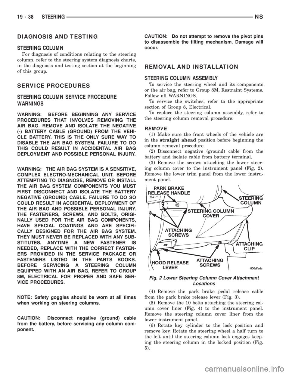
(3) Remove the screws attaching the lower steer-
ing column cover to the instrument panel (Fig. 2).
Remove the lower trim panel from the lower instru-
ment panel.
(4) Remove the park brake pedal release cable
from the park brake release lever (Fig. 3).
(5) Remove the 10 bolts attaching the steering col-
umn cover liner (Fig. 4) to the instrument panel.
Remove the steering column cover liner from the
lower instrument panel.
(6) Rotate key cylinder to the lock position and
remove key. Rotate the steering wheel a half turn to
the left until the steering column lock engages keep-
ing the steering column in the locked position (Fig.
5).
Fig. 2 Lower Steering Column Cover Attachment
Locations
19 - 38 STEERINGNS
Page 1465 of 1938
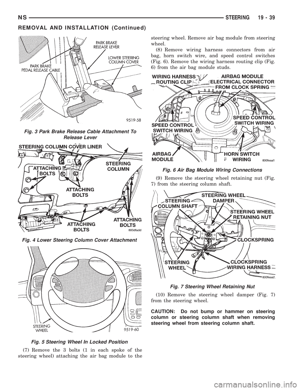
(7) Remove the 3 bolts (1 in each spoke of the
steering wheel) attaching the air bag module to thesteering wheel. Remove air bag module from steering
wheel.
(8) Remove wiring harness connectors from air
bag, horn switch wire, and speed control switches
(Fig. 6). Remove the wiring harness routing clip (Fig.
6) from the air bag module studs.
(9) Remove the steering wheel retaining nut (Fig.
7) from the steering column shaft.
(10) Remove the steering wheel damper (Fig. 7)
from the steering wheel.
CAUTION: Do not bump or hammer on steering
column or steering column shaft when removing
steering wheel from steering column shaft.
Fig. 3 Park Brake Release Cable Attachment To
Release Lever
Fig. 4 Lower Steering Column Cover Attachment
Fig. 5 Steering Wheel In Locked Position
Fig. 6 Air Bag Module Wiring Connections
Fig. 7 Steering Wheel Retaining Nut
NSSTEERING 19 - 39
REMOVAL AND INSTALLATION (Continued)
Page 1466 of 1938
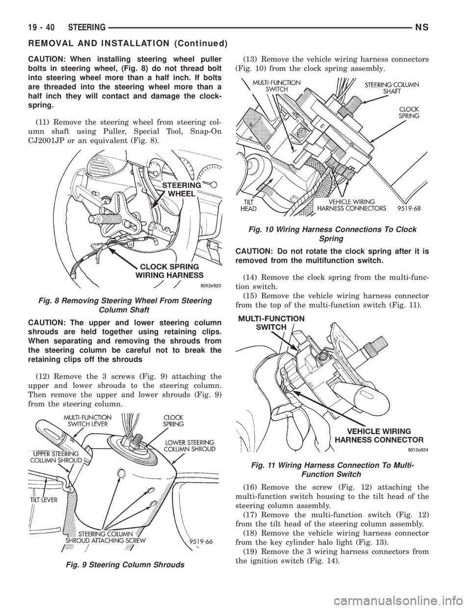
CAUTION: When installing steering wheel puller
bolts in steering wheel, (Fig. 8) do not thread bolt
into steering wheel more than a half inch. If bolts
are threaded into the steering wheel more than a
half inch they will contact and damage the clock-
spring.
(11) Remove the steering wheel from steering col-
umn shaft using Puller, Special Tool, Snap-On
CJ2001JP or an equivalent (Fig. 8).
CAUTION: The upper and lower steering column
shrouds are held together using retaining clips.
When separating and removing the shrouds from
the steering column be careful not to break the
retaining clips off the shrouds
(12) Remove the 3 screws (Fig. 9) attaching the
upper and lower shrouds to the steering column.
Then remove the upper and lower shrouds (Fig. 9)
from the steering column.(13) Remove the vehicle wiring harness connectors
(Fig. 10) from the clock spring assembly.
CAUTION: Do not rotate the clock spring after it is
removed from the multifunction switch.
(14) Remove the clock spring from the multi-func-
tion switch.
(15) Remove the vehicle wiring harness connector
from the top of the multi-function switch (Fig. 11).
(16) Remove the screw (Fig. 12) attaching the
multi-function switch housing to the tilt head of the
steering column assembly.
(17) Remove the multi-function switch (Fig. 12)
from the tilt head of the steering column assembly.
(18) Remove the vehicle wiring harness connector
from the key cylinder halo light (Fig. 13).
(19) Remove the 3 wiring harness connectors from
the ignition switch (Fig. 14).
Fig. 8 Removing Steering Wheel From Steering
Column Shaft
Fig. 9 Steering Column Shrouds
Fig. 10 Wiring Harness Connections To Clock
Spring
Fig. 11 Wiring Harness Connection To Multi-
Function Switch
19 - 40 STEERINGNS
REMOVAL AND INSTALLATION (Continued)
Page 1470 of 1938
CAUTION: Before installing the steering wheel the
clockspring must be centered. If clockspring is not
centered, the wiring in the clockspring may be over-
extended and break when the steering wheel is
rotated. Use the following procedure to center the
clockspring.
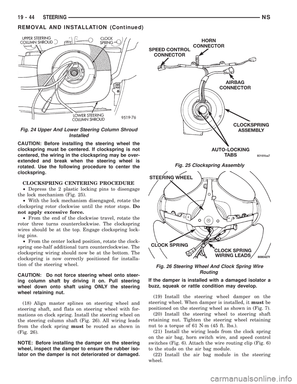
CLOCKSPRING CENTERING PROCEDURE
²Depress the 2 plastic locking pins to disengage
the lock mechanism (Fig. 25).
²With the lock mechanism disengaged, rotate the
clockspring rotor clockwise until the rotor stops.Do
not apply excessive force.
²From the end of the clockwise travel, rotate the
rotor three turns counterclockwise. The clockspring
wires should be at the top. Engage clockspring lock-
ing pins.
²From the center locked position, rotate the clock-
spring one-half additional turn counterclockwise. The
clockspring wiring should now be at the bottom. The
clockspring is now correctly positioned for installa-
tion of the steering wheel.
CAUTION: Do not force steering wheel onto steer-
ing column shaft by driving it on. Pull steering
wheel down onto shaft using ONLY the steering
wheel retaining nut.
(18) Align master splines on steering wheel and
steering shaft, and flats on steering wheel with for-
mations on clock spring. Install the steering wheel on
the steering column shaft (Fig. 26). All wiring leads
from the clock springmustbe routed as shown in
(Fig. 26).
NOTE: Before installing the damper on the steering
wheel, inspect the damper to ensure the rubber iso-
lator on the damper is not deteriorated or damaged.If the damper is installed with a damaged isolator a
buzz, squeak or rattle condition may develop.
(19) Install the steering wheel damper on the
steering wheel. When damper is installed, itmustbe
positioned on the steering wheel as shown in (Fig. 7).
(20) Install the steering wheel to steering shaft
retaining nut. Tighten the steering wheel retaining
nut to a torque of 61 N´m (45 ft. lbs.).
(21) Install the wiring leads from the clock spring
on the air bag, horn switch wire, and speed control
switches (Fig. 6). Attach the wire routing clip (Fig. 6)
to the studs on the air bag module.
(22) Install the air bag module in the steering
wheel.
Fig. 24 Upper And Lower Steering Column Shroud
Installed
Fig. 25 Clockspring Assembly
Fig. 26 Steering Wheel And Clock Spring Wire
Routing
19 - 44 STEERINGNS
REMOVAL AND INSTALLATION (Continued)
Page 1471 of 1938
(23) Install the 3 bolts (1 in each spoke of the
steering wheel) attaching the air bag module to the
steering wheel. Tighten the 3 air bag module attach-
ing nuts to a torque of 11 N´m (100 in. lbs.).
(24) Install the steering column cover liner (Fig. 4)
on the lower instrument panel. Install and securely
tighten the 10 bolts (Fig. 4) attaching the steering
column cover liner to the instrument panel.
(25) Install the park brake pedal release cable on
the park brake release lever in the lower steering col-
umn cover (Fig. 3).
(26) Install the lower steering column trim panel
on the lower instrument panel. Install and securely
the screws attaching the lower steering column cover
to the instrument panel (Fig. 2).
(27) Connect negative (ground) cable on the bat-
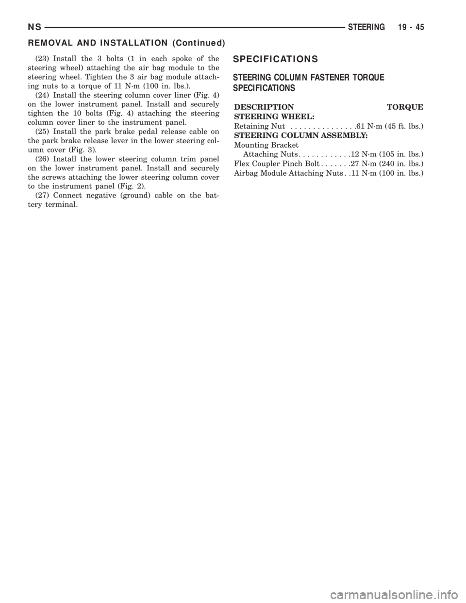
tery terminal.SPECIFICATIONS
STEERING COLUMN FASTENER TORQUE
SPECIFICATIONS
DESCRIPTION TORQUE
STEERING WHEEL:
Retaining Nut...............61N´m(45ft.lbs.)
STEERING COLUMN ASSEMBLY:
Mounting Bracket
Attaching Nuts............12N´m(105 in. lbs.)
Flex Coupler Pinch Bolt.......27N´m(240 in. lbs.)
Airbag Module Attaching Nuts . .11 N´m (100 in. lbs.)
NSSTEERING 19 - 45
REMOVAL AND INSTALLATION (Continued)
Page 1474 of 1938
(4) Raise the front wheels off the ground.
(5) Slowly turn the steering wheel right and left,
lightly contacting the wheel stops at least 20 times.
(6) Check the fluid level add if necessary.
(7) Lower the vehicle, start the engine and turn
the steering wheel slowly from lock to lock.
(8) Stop the engine and check the fluid level and
refill as required.
(9) If the fluid is extremely foamy or milky look-
ing, allow the vehicle to stand a few minutes and
repeat the procedure.
CAUTION: Do not run a vehicle with foamy fluid for
an extended period. This may cause pump damage.
REMOVAL AND INSTALLATION
POWER STEERING PUMPÐ2.5L DIESEL
NOTE: The power steering pump is mounted below
the fuel pump on the left side of the engine. The
vehicle should be raised on a hoist to access the
pump from below.
REMOVAL
(1) Remove serpentine drive belt. Refer to Group 7,
Cooling System, for procedure.
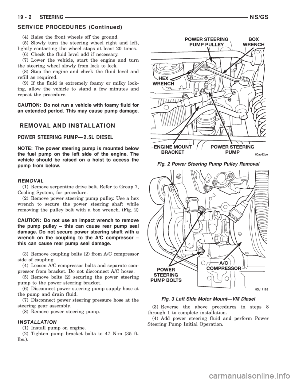
(2) Remove power steering pump pulley. Use a hex
wrench to secure the power steering shaft while
removing the pulley bolt with a box wrench. (Fig. 2)
CAUTION: Do not use an impact wrench to remove
the pump pulley ± this can cause rear pump seal
damage. Do not secure power steering shaft with a
wrench on the coupling to the A/C compressor ±
this can cause rear pump seal damage.
(3) Remove coupling bolts (2) from A/C compressor
side of coupling.
(4) Loosen A/C compressor bolts and separate com-
pressor from bracket. Do not disconnect A/C hoses.
(5) Remove bolts (2) securing the power steering
pump to the power steering bracket.
(6) Disconnect power steering pump supply hose at
the pump and drain fluid.
(7) Disconnect power steering pressure hose at the
steering gear assembly.
(8) Remove power steering pump.
INSTALLATION
(1) Install pump on engine.
(2) Tighten pump bracket bolts to 47 N´m (35 ft.
lbs.).(3) Reverse the above procedures in steps 8
through 1 to complete installation.
(4) Add power steering fluid and perform Power
Steering Pump Initial Operation.
Fig. 2 Power Steering Pump Pulley Removal
Fig. 3 Left SIde Motor MountÐVM DIesel
19 - 2 STEERINGNS/GS
SERVICE PROCEDURES (Continued)
Page 1669 of 1938
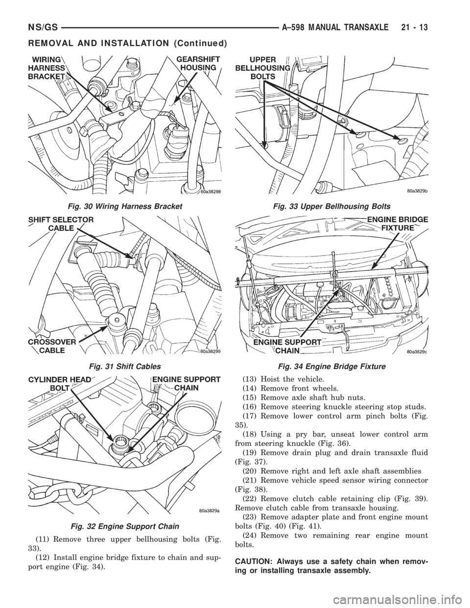
(11) Remove three upper bellhousing bolts (Fig.
33).
(12) Install engine bridge fixture to chain and sup-
port engine (Fig. 34).(13) Hoist the vehicle.
(14) Remove front wheels.
(15) Remove axle shaft hub nuts.
(16) Remove steering knuckle steering stop studs.
(17) Remove lower control arm pinch bolts (Fig.
35).
(18) Using a pry bar, unseat lower control arm
from steering knuckle (Fig. 36).
(19) Remove drain plug and drain transaxle fluid
(Fig. 37).
(20) Remove right and left axle shaft assemblies
(21) Remove vehicle speed sensor wiring connector
(Fig. 38).
(22) Remove clutch cable retaining clip (Fig. 39).
Remove clutch cable from transaxle housing.
(23) Remove adapter plate and front engine mount
bolts (Fig. 40) (Fig. 41).
(24) Remove two remaining rear engine mount
bolts.
CAUTION: Always use a safety chain when remov-
ing or installing transaxle assembly.
Fig. 30 Wiring Harness Bracket
Fig. 31 Shift Cables
Fig. 32 Engine Support Chain
Fig. 33 Upper Bellhousing Bolts
Fig. 34 Engine Bridge Fixture
NS/GSA±598 MANUAL TRANSAXLE 21 - 13
REMOVAL AND INSTALLATION (Continued)
Page 1674 of 1938
(12) Remove the front wheels.(13) Remove the two (2) axle shaft hub nuts.
(14) Remove three upper bellhousing bolts.
(15) Remove steering stop studs at steering knuck-
les.
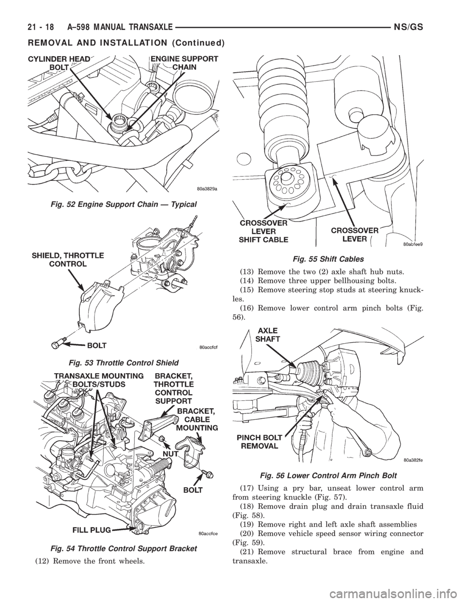
(16) Remove lower control arm pinch bolts (Fig.
56).
(17) Using a pry bar, unseat lower control arm
from steering knuckle (Fig. 57).
(18) Remove drain plug and drain transaxle fluid
(Fig. 58).
(19) Remove right and left axle shaft assemblies
(20) Remove vehicle speed sensor wiring connector
(Fig. 59).
(21) Remove structural brace from engine and
transaxle.
Fig. 52 Engine Support Chain Ð Typical
Fig. 53 Throttle Control Shield
Fig. 54 Throttle Control Support Bracket
Fig. 55 Shift Cables
Fig. 56 Lower Control Arm Pinch Bolt
21 - 18 A±598 MANUAL TRANSAXLENS/GS
REMOVAL AND INSTALLATION (Continued)