1996 CHRYSLER VOYAGER steering wheel
[x] Cancel search: steering wheelPage 1721 of 1938
Improper inflation can cause:
²Uneven wear patterns
²Reduced tread life
²Reduced fuel economy
²Unsatisfactory ride
²The vehicle to drift.
Proper tire air inflation pressure specifications can
be found on the Vehicle Tire Placard provided with
the vehicle. See owner's manual.
Tire pressures have been chosen to provide safe
operation, vehicle stability, and a smooth ride. Tire
pressure should be checked cold once per month.
Check tire pressure more frequently when the
weather temperature varies widely. Tire pressure will
decrease when the outdoor temperature drops.
Tire inflation pressures specified on the placard
are always cold inflation pressure. Cold inflation
pressure is obtained after the vehicle has not been
operated for at least 3 hours, or the vehicle is driven
less than one mile after being inoperative for 3
hours. Tire inflation pressures may increase from 2
to 6 pounds per square inch (psi) during operation.
Do not reduce this normal pressure build-up.
TIRE PRESSURE FOR HIGH-SPEED DRIVING
Chrysler Corporation advocates driving at safe
speeds within posted speed limits. Where speed lim-
its allow the vehicle to be driven at high speeds, cor-
rect tire inflation pressure is very important. For
speeds up to and including 75 mph (120 km/h), tires
must be inflated to the pressures shown on the tire
placard.
Vehicles loaded to the maximum capacity should
not be driven at speeds above 75 mph (120 km/h).
For emergency vehicles that are driven at speeds
over 90 mph (144 km/h), special high-speed tires
must be used. Consult tire manufacturer for correct
inflation pressure recommendations.
REPLACEMENT TIRES
The original equipment tires provide a proper bal-
ance of many characteristics such as:
²Ride
²Noise
²Handling
²Durability
²Tread life
²Traction
²Rolling resistance
²Speed capability
It is recommend that tires equivalent to the origi-
nal equipment tires be used when replacement is
needed.
Failure to use equivalent replacement tires may
adversely affect the safety and handling of the vehicle.
The use of oversize tires not listed in the specifica-
tion charts may cause interference with vehicle com-
ponents. Under extremes of suspension and steering
travel, interference with vehicle components may
cause tire damage.
WARNING: FAILURE TO EQUIP THE VEHICLE WITH
TIRES HAVING ADEQUATE SPEED CAPABILITY
CAN RESULT IN SUDDEN TIRE FAILURE.
DIAGNOSIS AND TESTING
PRESSURE GAUGES
A quality air pressure gauge is recommended to
check tire pressure. After checking the air pressure,
replace valve cap finger tight.
TREAD WEAR INDICATORS
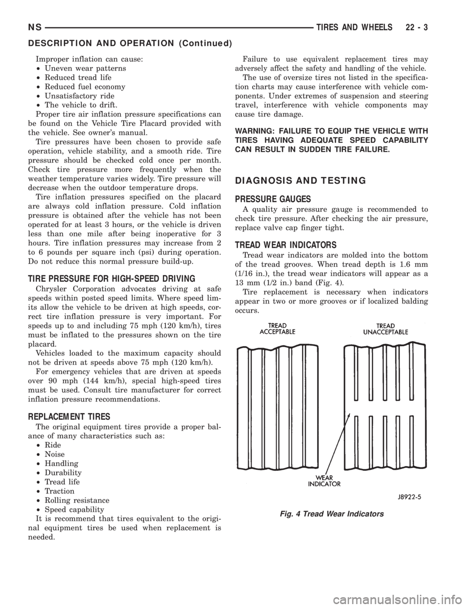
Tread wear indicators are molded into the bottom
of the tread grooves. When tread depth is 1.6 mm
(1/16 in.), the tread wear indicators will appear as a
13 mm (1/2 in.) band (Fig. 4).
Tire replacement is necessary when indicators
appear in two or more grooves or if localized balding
occurs.
Fig. 4 Tread Wear Indicators
NSTIRES AND WHEELS 22 - 3
DESCRIPTION AND OPERATION (Continued)
Page 1729 of 1938
SERVICE PROCEDURES
WHEEL INSTALLATION
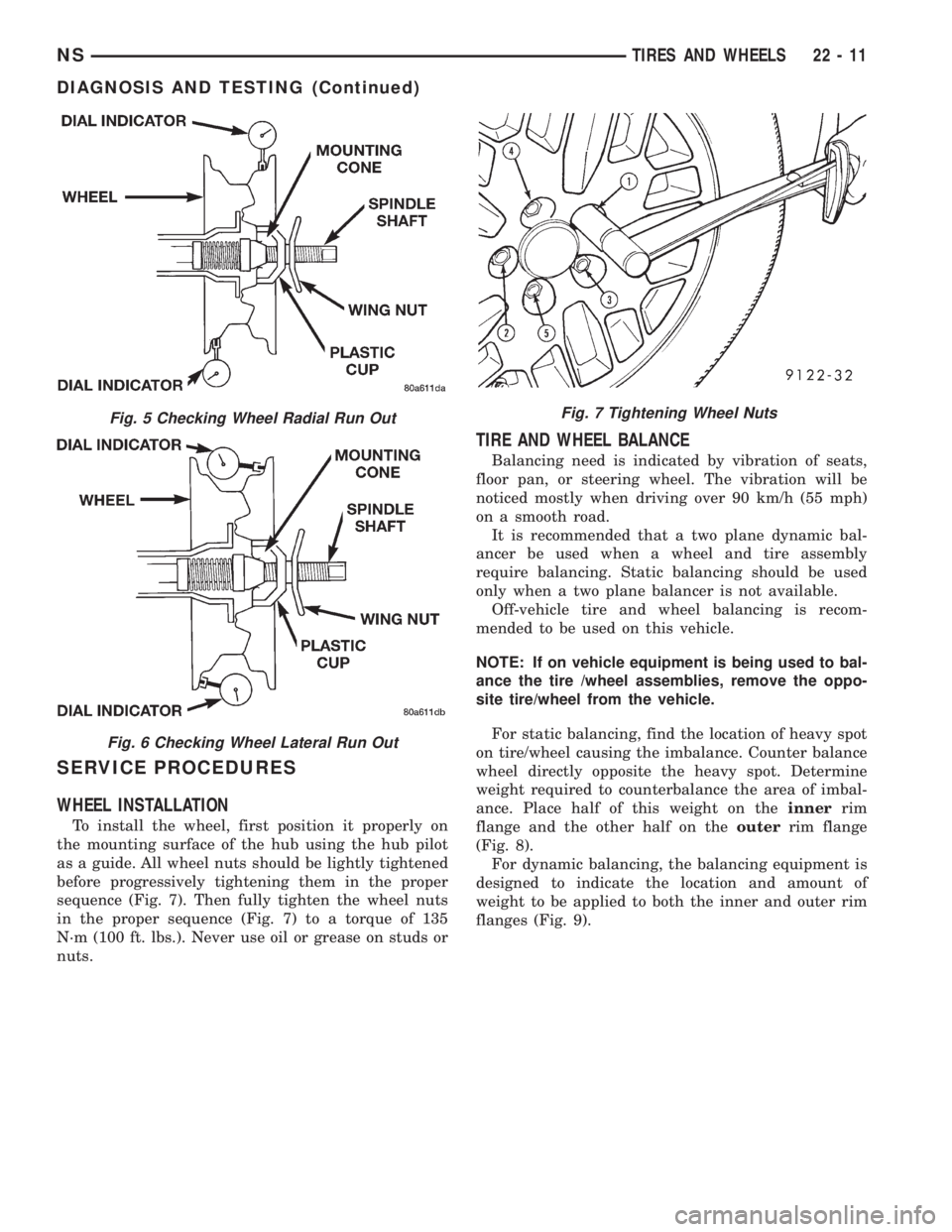
To install the wheel, first position it properly on
the mounting surface of the hub using the hub pilot
as a guide. All wheel nuts should be lightly tightened
before progressively tightening them in the proper
sequence (Fig. 7). Then fully tighten the wheel nuts
in the proper sequence (Fig. 7) to a torque of 135
N´m (100 ft. lbs.). Never use oil or grease on studs or
nuts.
TIRE AND WHEEL BALANCE
Balancing need is indicated by vibration of seats,
floor pan, or steering wheel. The vibration will be
noticed mostly when driving over 90 km/h (55 mph)
on a smooth road.
It is recommended that a two plane dynamic bal-
ancer be used when a wheel and tire assembly
require balancing. Static balancing should be used
only when a two plane balancer is not available.
Off-vehicle tire and wheel balancing is recom-
mended to be used on this vehicle.
NOTE: If on vehicle equipment is being used to bal-
ance the tire /wheel assemblies, remove the oppo-
site tire/wheel from the vehicle.
For static balancing, find the location of heavy spot
on tire/wheel causing the imbalance. Counter balance
wheel directly opposite the heavy spot. Determine
weight required to counterbalance the area of imbal-
ance. Place half of this weight on theinnerrim
flange and the other half on theouterrim flange
(Fig. 8).
For dynamic balancing, the balancing equipment is
designed to indicate the location and amount of
weight to be applied to both the inner and outer rim
flanges (Fig. 9).
Fig. 5 Checking Wheel Radial Run Out
Fig. 6 Checking Wheel Lateral Run Out
Fig. 7 Tightening Wheel Nuts
NSTIRES AND WHEELS 22 - 11
DIAGNOSIS AND TESTING (Continued)
Page 1773 of 1938
(3) Install hood latch cable.
(4) Install lower steering column cover and knee
blocker reinforcement.
JACK STORAGE COVER
LONG WHEEL BASE
REMOVAL
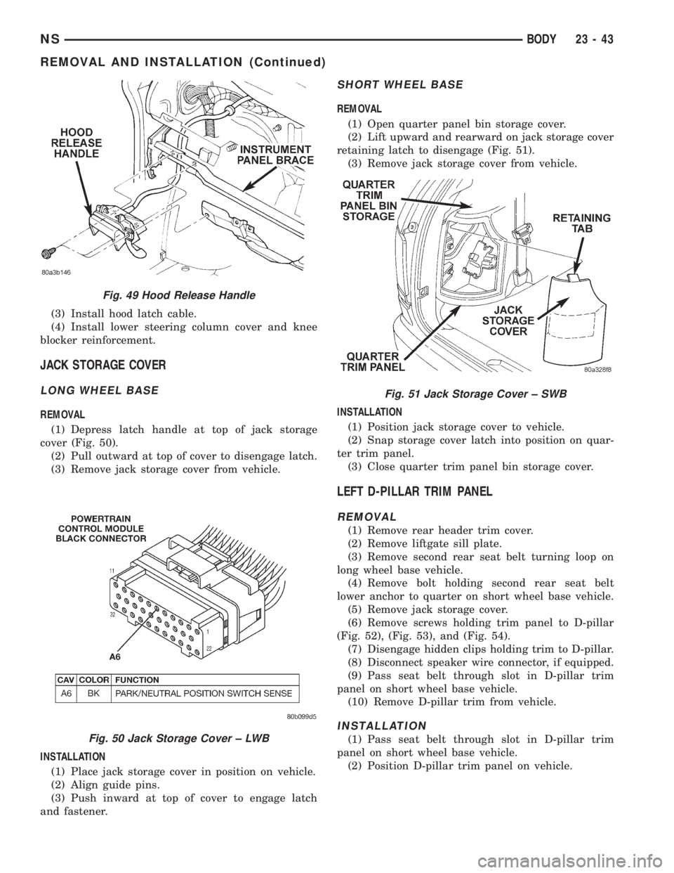
(1) Depress latch handle at top of jack storage
cover (Fig. 50).
(2) Pull outward at top of cover to disengage latch.
(3) Remove jack storage cover from vehicle.
INSTALLATION
(1) Place jack storage cover in position on vehicle.
(2) Align guide pins.
(3) Push inward at top of cover to engage latch
and fastener.
SHORT WHEEL BASE
REMOVAL
(1) Open quarter panel bin storage cover.
(2) Lift upward and rearward on jack storage cover
retaining latch to disengage (Fig. 51).
(3) Remove jack storage cover from vehicle.
INSTALLATION
(1) Position jack storage cover to vehicle.
(2) Snap storage cover latch into position on quar-
ter trim panel.
(3) Close quarter trim panel bin storage cover.
LEFT D-PILLAR TRIM PANEL
REMOVAL
(1) Remove rear header trim cover.
(2) Remove liftgate sill plate.
(3) Remove second rear seat belt turning loop on
long wheel base vehicle.
(4) Remove bolt holding second rear seat belt
lower anchor to quarter on short wheel base vehicle.
(5) Remove jack storage cover.
(6) Remove screws holding trim panel to D-pillar
(Fig. 52), (Fig. 53), and (Fig. 54).
(7) Disengage hidden clips holding trim to D-pillar.
(8) Disconnect speaker wire connector, if equipped.
(9) Pass seat belt through slot in D-pillar trim
panel on short wheel base vehicle.
(10) Remove D-pillar trim from vehicle.
INSTALLATION
(1) Pass seat belt through slot in D-pillar trim
panel on short wheel base vehicle.
(2) Position D-pillar trim panel on vehicle.
Fig. 49 Hood Release Handle
Fig. 50 Jack Storage Cover ± LWB
Fig. 51 Jack Storage Cover ± SWB
NSBODY 23 - 43
REMOVAL AND INSTALLATION (Continued)
Page 1886 of 1938
REMOVAL
(1) Disconnect the battery negative cable.
(2) Recover A/C system refrigerant.
(3) Unscrew the High Side service port from the
liquid line.
(4) Remove O-ring
INSTALLATION
For installation, reverse the above procedures.
²Install new O-ring.
²Evacuate and recharge A/C system.
BLEND-AIR DOOR ACTUATOR
REMOVAL
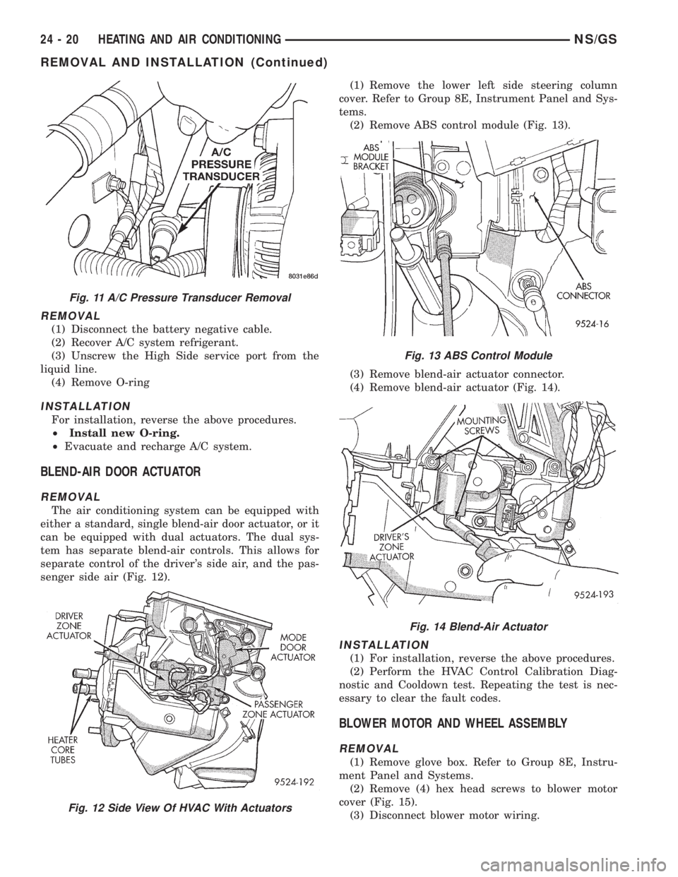
The air conditioning system can be equipped with
either a standard, single blend-air door actuator, or it
can be equipped with dual actuators. The dual sys-
tem has separate blend-air controls. This allows for
separate control of the driver's side air, and the pas-
senger side air (Fig. 12).(1) Remove the lower left side steering column
cover. Refer to Group 8E, Instrument Panel and Sys-
tems.
(2) Remove ABS control module (Fig. 13).
(3) Remove blend-air actuator connector.
(4) Remove blend-air actuator (Fig. 14).
INSTALLATION
(1) For installation, reverse the above procedures.
(2) Perform the HVAC Control Calibration Diag-
nostic and Cooldown test. Repeating the test is nec-
essary to clear the fault codes.
BLOWER MOTOR AND WHEEL ASSEMBLY
REMOVAL
(1) Remove glove box. Refer to Group 8E, Instru-
ment Panel and Systems.
(2) Remove (4) hex head screws to blower motor
cover (Fig. 15).
(3) Disconnect blower motor wiring.
Fig. 11 A/C Pressure Transducer Removal
Fig. 12 Side View Of HVAC With Actuators
Fig. 13 ABS Control Module
Fig. 14 Blend-Air Actuator
24 - 20 HEATING AND AIR CONDITIONINGNS/GS
REMOVAL AND INSTALLATION (Continued)
Page 1888 of 1938
(3) Remove resistor block by inserting a flat blade
pry tool on the side of the resistor block and pushing
inward. Two guide lines are shown on the right hand
edge of the resistor block to help guide the blade
position. This will release the clips on the side of the
resistor block. Pull resistor block out.
INSTALLATION
For installation, reverse the above procedures.
Make sure the ªTOPº lettering is on the top of the
resistor. The coils on the Resistor Block should not be
contacting one another. Before installation, gently
separate the coils (with fingers only) if one coil is
contacting another.
BLOWER MOTOR WHEEL
The blower motor wheel is not serviced separately.
If the wheel needs to be replaced it is serviced as an
assembly of the blower motor. For service procedure
information, refer to Blower Motor Replacement in
this group.
COMPRESSOR (2.5L TURBO DIESEL)
REMOVAL
WARNING: REFER TO REFRIGERANT SERVICE
PROCEDURES FOR INFORMATION REGARDING
PROPER RECOVERY OF THE REFRIGERANT
BEFORE ATTEMPTING TO REMOVE THE COM-
PRESSOR.(1) Disconnect negative battery cable.
(2) Reclaim refrigerant.
(3) Raise vehicle on hoist.
(4) Remove refrigerant lines from compressor and
cap all lines (Fig. 10).
(5) Remove flex drive bolts from behind the power
steering pump (Fig. 20).
(6) Remove compressor mounting bolts (Fig. 20).
(7) pry compressor off of the dowel pins and
remove compressor.
INSTALLATION
(1) Transfer mounting spacer/bushings onto the
new compressor.
(2) Lift compressor into place and start compressor
mounting bolts. Do not tighten bolts at this time. The
compressor may have to be moved slightly to align
the flex drive bolts.
(3) Align compressor clutch with flex drive. Then
start both flex drive bolts. Tighten the bolts after
both flex drive bolts have been installed.
(4) Tighten compressor mounting bolts.
(5) Lower vehicle and install refrigerant lines.
Always replace O-rings and gaskets.
(6) Evacuate refrigerant system. Charge system
with the correct amount of R-134a refrigerant. The
refrigerant capacity is .91 kg.67 gm. (32 oz.62.0
oz.).
24 - 22 HEATING AND AIR CONDITIONINGNS/GS
REMOVAL AND INSTALLATION (Continued)
Page 1920 of 1938
the inlet. This results in maximum vapor flow
through the valve (Fig. 9).
CRANKCASE VENT FILTER
All engines use filtered air to vent the crankcase.
The filtered air is drawn through the resonator
assembly located between the air cleaner and throttle
body.
VEHICLE EMISSION CONTROL INFORMATION
LABEL
All models have a Vehicle Emission Control Infor-
mation (VECI) Label. Chrysler permanently attaches
the label in the engine compartment. It cannot be
removed without defacing information and destroying
the label.
The label contains the vehicle's emission specifica-
tions and vacuum hose routings. All hoses must be
connected and routed according to the label.
DIAGNOSIS AND TESTING
LEAK DETECTION PUMP
Refer to the appropriate Powertrain Diagnostic
Procedures Manual for testing procedures.
PCV VALVE TEST
WARNING: APPLY PARKING BRAKE AND/OR
BLOCK WHEELS BEFORE PERFORMING ANY TEST
OR ADJUSTMENT WITH THE ENGINE OPERATING.
With the engine idling, remove the PCV valve from
its attaching point. If the valve is operating properly,
a hissing noise will be heard and a strong vacuum
felt when placing a finger over the valve inlet (Fig.
10). With the engine off, shake the valve. The valve
should rattle when shaken. Replace the valve if it
does not operate properly.Do not attempt to clean
the PCV valve.
REMOVAL AND INSTALLATION
LEAK DETECTION PUMP REPLACEMENT
REMOVAL
The Leak Detection Pump (LDP) is located under
the driver's side in the cast cradle under the steering
gear (Fig. 11).
(1) Raise and support vehicle on a hoist.
Fig. 9 Moderate Intake Manifold VacuumÐMaximum
Vapor Flow
Fig. 10 PCV Test ÐTypical
Fig. 11 Leak Detection Pump
25 - 16 EMISSION CONTROL SYSTEMSNS
DESCRIPTION AND OPERATION (Continued)
Page 1923 of 1938
the amount of EGR supplied to the engine. This pro-
vides the correct amount of exhaust gas recirculation
for different operating conditions.
This system does not allow EGR at idle. The EGR
systems can operate at all coolant temperatures
above 60ÉF as long as the battery ambient tempera-
ture is above 7ÉF.
DIAGNOSIS AND TESTING
EGR SYSTEM ON-BOARD DIAGNOSTICS
The PCM performs an on-board diagnostic check of
the EGR system. The diagnostic system uses the
electronic EGR transducer for the system tests.
The diagnostic check activates only during selected
engine/driving conditions. When the conditions are
met, the PCM energizes the transducer solenoid to
disable the EGR. The PCM checks for a change in
the heated oxygen sensor signal. If the air-fuel mix-
ture goes lean, the PCM will attempt to enrichen the
mixture. The PCM registers a Diagnostic Trouble
Code (DTC) if the EGR system is not operating cor-
rectly. After registering a DTC, the PCM turns on the
malfunction indicator (Check Engine) lamp after 2
consecutive trips. There are 2 types of failures sensed
by the PCM. The first is a short or open in the elec-
trical solenoid circuit. The second is a mechanical
failure or loss of vacuum. The Malfunction Indicator
Lamp (MIL) indicates the need for service.
If a problem is indicated by the MIL and a DTC for
the EGR system is set, check for proper operation of
the EGR system. Use the System Test, EGR Gas
Flow Test. If the EGR system tests properly, check
the system using the DRB scan tool. Refer to
On-Board Diagnosis sections in this Group. Also,
refer to the DRB scan tool and the appropriate Pow-
ertrain Diagnostics Procedure manual.
EGR SYSTEM TEST
WARNING: APPLY PARKING BRAKE AND/OR
BLOCK WHEELS BEFORE TESTING THE EGR SYS-
TEM.
(1) Check the condition of all EGR system hoses
and tubes for leaks, cracks, kinks and hardening of
rubber hoses. Repair and correct these conditions
before performing any tests.
(2) Be sure the hoses at both the EGR valve and
EGR valve control are connected to the proper fit-
tings (Fig. 4).
(3) Be sure the electrical connector is firmly con-
nected at the valve control.
(4) To check EGR system operation, connect the
DRB scan tool to the 16±way data link connector.
The data link connector is located on the lower edge
of the instrument panel near the steering column.
Refer to the appropriate Powertrain Diagnostic Pro-
cedures service manual for operation of the DRB
scan tool when diagnosing the EGR system.
(5) After checking the system with the DRB scan
tool, proceed to the following EGR Valve Leakage and
EGR Valve Control Tests and repair as necessary.
Fig. 3 Electric EGR Transducer Assembly
Fig. 4 EGR Value and EGR Value ÐTypical
NSEMISSION CONTROL SYSTEMS 25 - 19
DESCRIPTION AND OPERATION (Continued)