1996 CHRYSLER VOYAGER steering wheel
[x] Cancel search: steering wheelPage 1223 of 1938
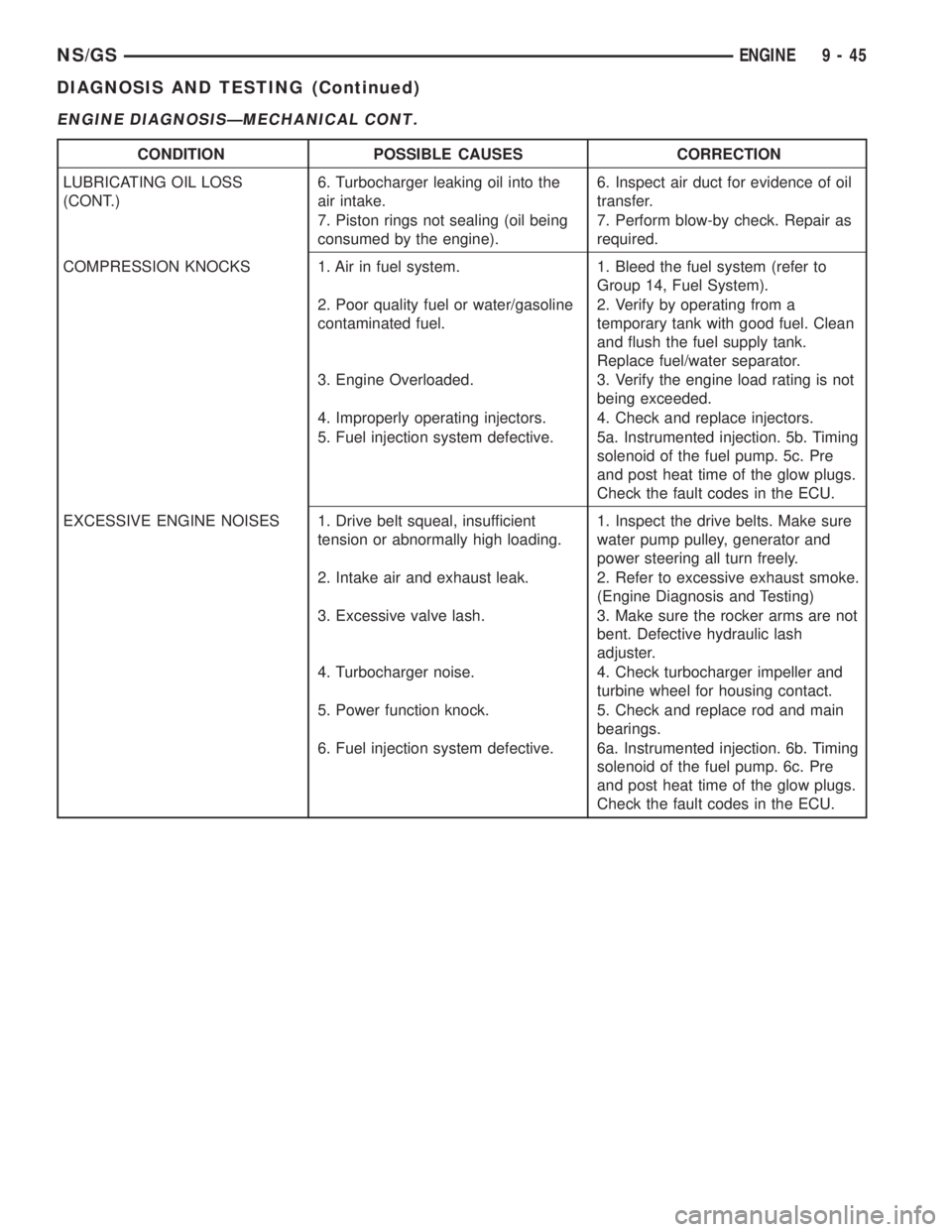
ENGINE DIAGNOSISÐMECHANICAL CONT.
CONDITION POSSIBLE CAUSES CORRECTION
LUBRICATING OIL LOSS
(CONT.)6. Turbocharger leaking oil into the
air intake.6. Inspect air duct for evidence of oil
transfer.
7. Piston rings not sealing (oil being
consumed by the engine).7. Perform blow-by check. Repair as
required.
COMPRESSION KNOCKS 1. Air in fuel system. 1. Bleed the fuel system (refer to
Group 14, Fuel System).
2. Poor quality fuel or water/gasoline
contaminated fuel.2. Verify by operating from a
temporary tank with good fuel. Clean
and flush the fuel supply tank.
Replace fuel/water separator.
3. Engine Overloaded. 3. Verify the engine load rating is not
being exceeded.
4. Improperly operating injectors. 4. Check and replace injectors.
5. Fuel injection system defective. 5a. Instrumented injection. 5b. Timing
solenoid of the fuel pump. 5c. Pre
and post heat time of the glow plugs.
Check the fault codes in the ECU.
EXCESSIVE ENGINE NOISES 1. Drive belt squeal, insufficient
tension or abnormally high loading.1. Inspect the drive belts. Make sure
water pump pulley, generator and
power steering all turn freely.
2. Intake air and exhaust leak. 2. Refer to excessive exhaust smoke.
(Engine Diagnosis and Testing)
3. Excessive valve lash. 3. Make sure the rocker arms are not
bent. Defective hydraulic lash
adjuster.
4. Turbocharger noise. 4. Check turbocharger impeller and
turbine wheel for housing contact.
5. Power function knock. 5. Check and replace rod and main
bearings.
6. Fuel injection system defective. 6a. Instrumented injection. 6b. Timing
solenoid of the fuel pump. 6c. Pre
and post heat time of the glow plugs.
Check the fault codes in the ECU.
NS/GSENGINE 9 - 45
DIAGNOSIS AND TESTING (Continued)
Page 1239 of 1938
(3) Install cylinder head, intake manifold, and
exhaust manifold. Refer to cylinder head installation
in this section.
(4) Install push rods in original positions.
(5) Install rocker arms in original positions.
(6) Install cylinder head cover. Refer to cylinder
valve cover installation in this section.
(7) Start and operate engine. Warm up to normal
operating temperature.
CAUTION: To prevent damage to valve mechanism,
engine must not be run above fast idle until all
hydraulic tappets have filled with oil and have
become quiet.
VIBRATION DAMPER
REMOVAL
(1) Disconnect the battery cable.
(2) Raise vehicle on hoist.
(3) Remove right side lower splash shield.
(4) Remove generator, power steering belt. Refer to
Group 7, Cooling.
(5) Remove water pump belt. Refer to Group 7,
Cooling.
(6) Remove engine starter. Refer to Group, 8B for
procedure
(7) Install flywheel locking tool VM.1014 to pre-
vent engine rotation.
NOTE: Crankshaft damper nut is left handed
thread.
(8) Remove vibration damper nut.
(9) Remove vibration damper. No special tool is
needed for removal.
CAUTION: If thread sealant is used it is important
to remove all the old thread sealant from the
threads on the crankshaft.
INSTALLATION
NOTE: Before installing damper be sure the O-ring
inside the center of the damper is in its grove.
(1) Install vibration damper.
CAUTION: Correct torque on the vibration damper
nut is important or engine damage can occur.
(2) Install vibration damper nut and tighten to 441
N´m (325 ft. lbs.).
(3) Remove flywheel locking tool, and install
engine starter.(4) Install both accessary drive belts. Refer to
Group 7, Cooling.
(5) Install right splash shield.
(6) Lower vehicle.
(7) Connect the battery cable.
TIMING GEAR COVER OIL SEAL
REMOVAL
(1) Disconnect the battery cable.
(2) Remove vibration damper. Refer to vibration
damper removal in this section.
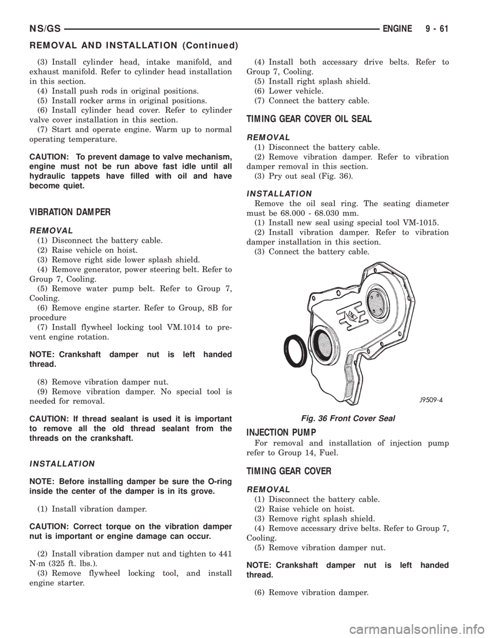
(3) Pry out seal (Fig. 36).
INSTALLATION
Remove the oil seal ring. The seating diameter
must be 68.000 - 68.030 mm.
(1) Install new seal using special tool VM-1015.
(2) Install vibration damper. Refer to vibration
damper installation in this section.
(3) Connect the battery cable.
INJECTION PUMP
For removal and installation of injection pump
refer to Group 14, Fuel.
TIMING GEAR COVER
REMOVAL
(1) Disconnect the battery cable.
(2) Raise vehicle on hoist.
(3) Remove right splash shield.
(4) Remove accessary drive belts. Refer to Group 7,
Cooling.
(5) Remove vibration damper nut.
NOTE: Crankshaft damper nut is left handed
thread.
(6) Remove vibration damper.
Fig. 36 Front Cover Seal
NS/GSENGINE 9 - 61
REMOVAL AND INSTALLATION (Continued)
Page 1283 of 1938
FRAME
INDEX
page page
REMOVAL AND INSTALLATION
FRONT CROSSMEMBER MOUNT BUSHINGS . . . 5
FRONT CROSSMEMBER................... 3SPECIFICATIONS
FRAME AND BODY OPENING DIMENSIONS.... 5
REMOVAL AND INSTALLATION
FRONT CROSSMEMBER
The front suspension crossmember must be
installed in the design location to achieve proper
front end suspension alignment. If the crossmember
is removed without applying reference marks on the
frame rails, align the crossmember according to the
dimensions provided in this group.
NOTE: If the caged nuts in the frame rails become
damaged and cannot be reused, a replacement nut
can be obtained through a MoparTParts supplier.
REMOVAL
(1) Disconnect battery negative cable.
(2) Remove steering column lower cover from
instrument panel. Refer to Group 8E, Instrument
Panel and Systems.
(3) Remove knee blocker reinforcement. Refer to
Group 8E, Instrument Panel and Systems.
(4) Position steering so front wheels are straight
ahead.
CAUTION: Do not rotate steering wheel after disen-
gaging lower coupling from steering gear, damage
to airbag clock spring can result.
(5) Remove clinch bolt holding steering column
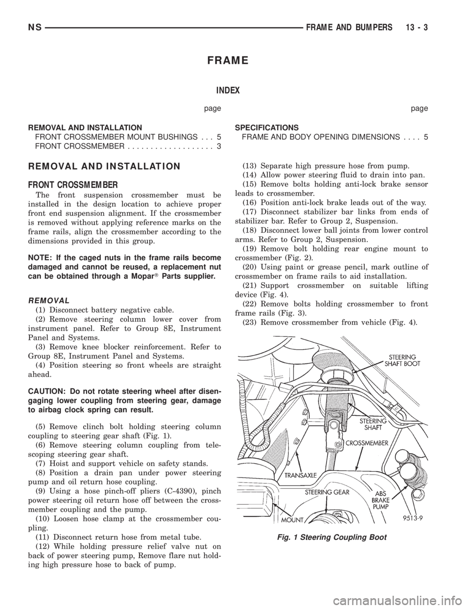
coupling to steering gear shaft (Fig. 1).
(6) Remove steering column coupling from tele-
scoping steering gear shaft.
(7) Hoist and support vehicle on safety stands.
(8) Position a drain pan under power steering
pump and oil return hose coupling.
(9) Using a hose pinch-off pliers (C-4390), pinch
power steering oil return hose off between the cross-
member coupling and the pump.
(10) Loosen hose clamp at the crossmember cou-
pling.
(11) Disconnect return hose from metal tube.
(12) While holding pressure relief valve nut on
back of power steering pump, Remove flare nut hold-
ing high pressure hose to back of pump.(13) Separate high pressure hose from pump.
(14) Allow power steering fluid to drain into pan.
(15) Remove bolts holding anti-lock brake sensor
leads to crossmember.
(16) Position anti-lock brake leads out of the way.
(17) Disconnect stabilizer bar links from ends of
stabilizer bar. Refer to Group 2, Suspension.
(18) Disconnect lower ball joints from lower control
arms. Refer to Group 2, Suspension.
(19) Remove bolt holding rear engine mount to
crossmember (Fig. 2).
(20) Using paint or grease pencil, mark outline of
crossmember on frame rails to aid installation.
(21) Support crossmember on suitable lifting
device (Fig. 4).
(22) Remove bolts holding crossmember to front
frame rails (Fig. 3).
(23) Remove crossmember from vehicle (Fig. 4).
Fig. 1 Steering Coupling Boot
NSFRAME AND BUMPERS 13 - 3
Page 1285 of 1938
(7) Connect lower ball joints to lower control arms.
Refer to Group 2, Suspension.
(8) Connect stabilizer bar links to ends of stabi-
lizer bar. Refer to Group 2, Suspension.
(9) Install bolts to hold anti-lock brake sensor
leads to crossmember.
(10) Install high pressure hose to pump.
(11) Connect return hose to metal tube.
(12) Tighten hose clamp at the crossmember cou-
pling.
(13) Remove pinch-off pliers.
(14) Position steering so front wheels are straight
ahead.
(15) Install steering column coupling to telescoping
steering gear shaft.
(16) Install clinch bolt to hold steering column cou-
pling to steering gear shaft.
(17) Install knee blocker reinforcement. Refer to
Group 8E, Instrument Panel and Systems.
(18) Install steering column lower cover from
instrument panel. Refer to Group 8E, Instrument
Panel and Systems.
(19) Connect battery negative cable.
FRONT CROSSMEMBER MOUNT BUSHINGS
REMOVAL
(1) Using paint or grease pencil, mark outline of
crossmember on frame rails.
(2) Loosen bolts holding crossmember to frame
rails.
(3) Remove bolt on bushing that requires replace-
ment.
(4) Allow crossmember to drop down enough to
gain clearance for bushing removal.
(5) Remove bushing from vehicle.
INSTALLATION
(1) Apply rubber lube or soap to replacement bush-
ing.(2) Insert lower half of bushing into square hole in
crossmember.
(3) Place upper half of bushing on top of cross-
member aligned to receive square tube protruding
upward from lower bushing half.
(4) Squeeze bushing halves together to ensure they
are properly mated.
(5) Lift crossmember upward to close gap between
the bushing and frame.
(6) Verify that lower bushing is fully seated into
crossmember and upper bushing.
(7) Install bolt to hold bushing and crossmember
to frame rail hand tight.
(8) Align crossmember to reference marks on
frame rails.
(9) Tighten crossmember to frame rails attaching
bolts to 163 N´m (120 ft. lbs.) torque.
SPECIFICATIONS
FRAME AND BODY OPENING DIMENSIONS
Frame dimensions are listed in metric scale. All
dimensions are from center to center of Principal
Locating Point (PLP), or from center to center of PLP
and fastener location.
VEHICLE PREPARATION
Position the vehicle on a frame alignment rack,
refer to instructions provided with equipment being
used. Adjust the vehicle PLP heights to the specified
dimension above the work surface (datum line). Ver-
tical dimensions can be taken from the datum line to
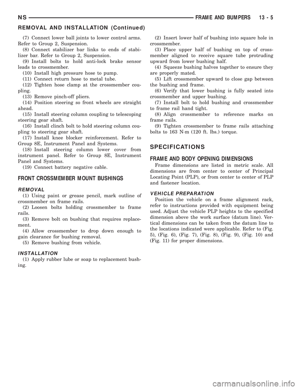
the locations indicated were applicable. Refer to (Fig.
5), (Fig. 6), (Fig. 7), (Fig. 8), (Fig. 9), (Fig. 10) and
(Fig. 11) for proper dimensions.
NSFRAME AND BUMPERS 13 - 5
REMOVAL AND INSTALLATION (Continued)
Page 1427 of 1938
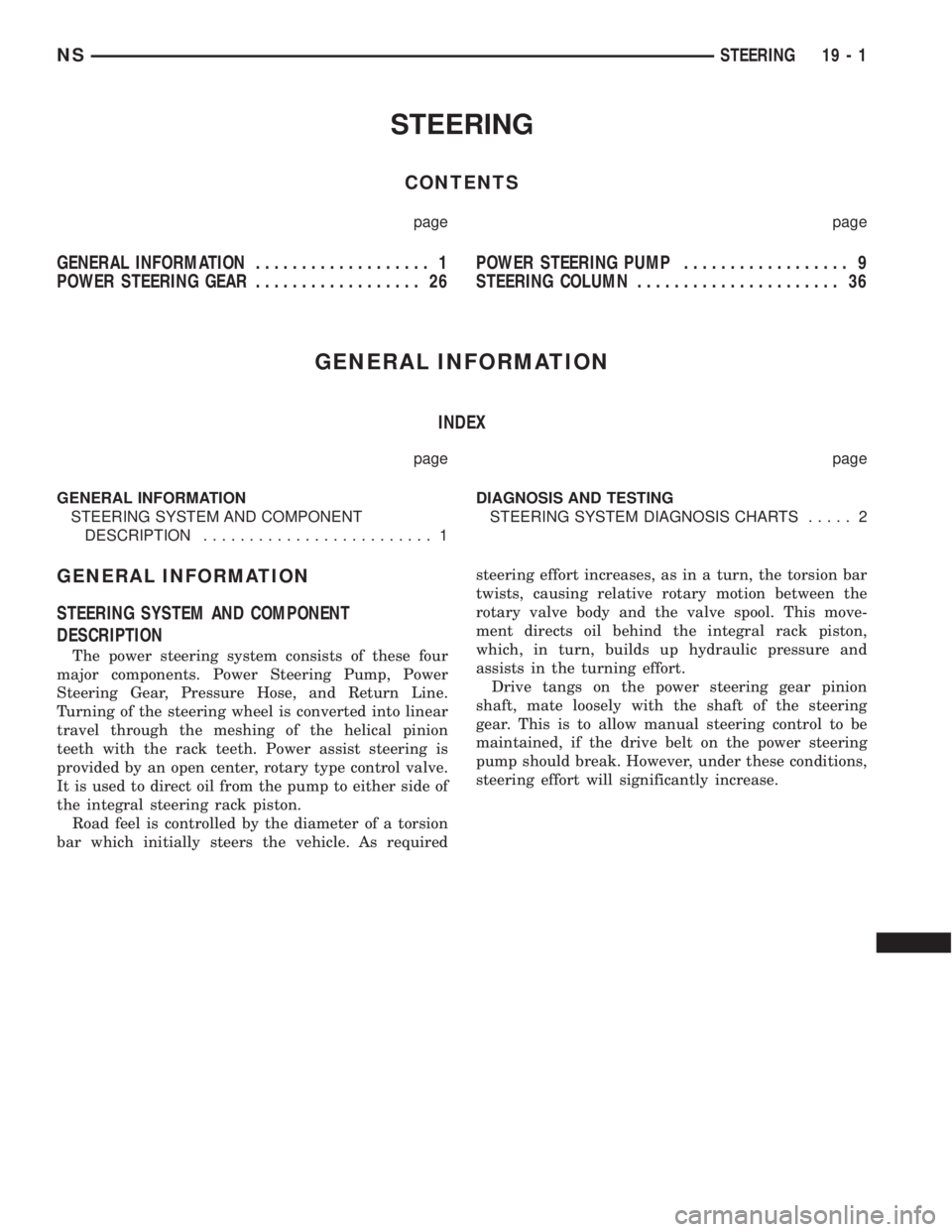
STEERING
CONTENTS
page page
GENERAL INFORMATION................... 1
POWER STEERING GEAR.................. 26POWER STEERING PUMP.................. 9
STEERING COLUMN...................... 36
GENERAL INFORMATION
INDEX
page page
GENERAL INFORMATION
STEERING SYSTEM AND COMPONENT
DESCRIPTION......................... 1DIAGNOSIS AND TESTING
STEERING SYSTEM DIAGNOSIS CHARTS..... 2
GENERAL INFORMATION
STEERING SYSTEM AND COMPONENT
DESCRIPTION
The power steering system consists of these four
major components. Power Steering Pump, Power
Steering Gear, Pressure Hose, and Return Line.
Turning of the steering wheel is converted into linear
travel through the meshing of the helical pinion
teeth with the rack teeth. Power assist steering is
provided by an open center, rotary type control valve.
It is used to direct oil from the pump to either side of
the integral steering rack piston.
Road feel is controlled by the diameter of a torsion
bar which initially steers the vehicle. As requiredsteering effort increases, as in a turn, the torsion bar
twists, causing relative rotary motion between the
rotary valve body and the valve spool. This move-
ment directs oil behind the integral rack piston,
which, in turn, builds up hydraulic pressure and
assists in the turning effort.
Drive tangs on the power steering gear pinion
shaft, mate loosely with the shaft of the steering
gear. This is to allow manual steering control to be
maintained, if the drive belt on the power steering
pump should break. However, under these conditions,
steering effort will significantly increase.
NSSTEERING 19 - 1
Page 1428 of 1938
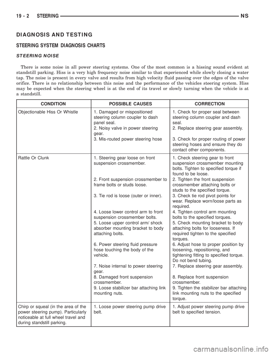
DIAGNOSIS AND TESTING
STEERING SYSTEM DIAGNOSIS CHARTS
STEERING NOISE
There is some noise in all power steering systems. One of the most common is a hissing sound evident at
standstill parking. Hiss is a very high frequency noise similar to that experienced while slowly closing a water
tap. The noise is present in every valve and results from high velocity fluid passing over the edges of the valve
orifice. There is no relationship between this noise and the performance of the vehicles steering system. Hiss
may be expected when the steering wheel is at the end of its travel or slowly turning when the vehicle is at
a standstill.
CONDITION POSSIBLE CAUSES CORRECTION
Objectionable Hiss Or Whistle 1. Damaged or mispositioned
steering column coupler to dash
panel seal.1. Check for proper seal between
steering column coupler and dash
seal.
2. Noisy valve in power steering
gear.2. Replace steering gear assembly.
3. Mis-routed power steering hose 3. Check for proper routing of power
steering hoses and ensure they do
contact other components.
Rattle Or Clunk 1. Steering gear loose on front
suspension crossmember.1. Check steering gear to front
suspension crossmember mounting
bolts. Tighten to specified torque if
found to be loose.
2. Front suspension crossmember to
frame bolts or studs loose.2. Tighten the front suspension
crossmember attaching bolts or
studs to the specified torque.
3. Tie rod is loose (outer or inner). 3. Check tie rod pivot points for
wear. Replace worn/loose parts as
required.
4. Loose lower control arm to front
suspension crossmember bolts.4. Tighten control arm mounting
bolts to the specified torques.
5. Loose upper control arm/ shock
absorber mounting bracket to body
attaching bolts.5. Check mounting bracket to body
attaching bolts for looseness. If
required tighten to the specified
torques.
6. Power steering fluid pressure
hose touching the body of the
vehicle.6. Adjust hose to proper position by
loosening, repositioning, and
tightening fitting to specified torque.
Do not bend tubing.
7. Noise internal to power steering
gear.7. Replace steering gear assembly.
8. Damaged front suspension
crossmember.8. Replace front suspension
crossmember.
9. Loose stabilizer bar attaching link
mounting nuts.9. Tighten the stabilizer bar attaching
link mounting nuts to the specified
torque.
Chirp or squeal (in the area of the
power steering pump). Particularly
noticeable at full wheel travel and
during standstill parking.1. Loose power steering pump drive
belt.1. Adjust power steering pump drive
belt to specified tension.
19 - 2 STEERINGNS
Page 1429 of 1938
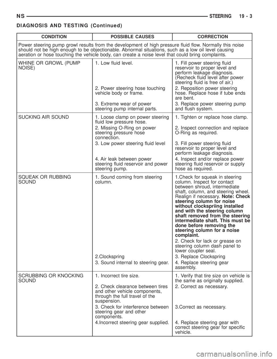
CONDITION POSSIBLE CAUSES CORRECTION
Power steering pump growl results from the development of high pressure fluid flow. Normally this noise
should not be high enough to be objectionable. Abnormal situations, such as a low oil level causing
aeration or hose touching the vehicle body, can create a noise level that could bring complaints.
WHINE OR GROWL (PUMP
NOISE)1. Low fluid level. 1. Fill power steering fluid
reservoir to proper level and
perform leakage diagnosis.
(Recheck fluid level after power
steering fluid is free of air.)
2. Power steering hose touching
vehicle body or frame.2. Reposition power steering
hose. Replace hose if tube ends
are bent.
3. Extreme wear of power
steering pump internal parts.3. Replace power steering pump
and flush system.
SUCKING AIR SOUND 1. Loose clamp on power steering
fluid low pressure hose.1. Tighten or replace hose clamp.
2. Missing O-Ring on power
steering pressure hose
connection.2. Inspect connection and replace
O-Ring as required.
3. Low power steering fluid level 3. Fill power steering fluid
reservoir to proper level and
perform leakage diagnosis.
4. Air leak between power
steering fluid reservoir and power
steering pump.4. Inspect and/or replace power
steering fluid reservoir or supply
hose as required.
SQUEAK OR RUBBING
SOUND1. Sound coming from steering
column.1.Check for squeak in steering
column. Inspect for contact
between shroud, intermediate
shaft, column, and steering wheel.
Realign if necessary.Note: Check
steering column for noise
without clockspriing installed
and with the steering column
shaft removed from the steering
intermediate shaft. This must be
done before removing the
steering column for a noise
complaint.
2. Check for lack or grease on
steering column dash panel to
lower coupler seal.
2.Clockspring 3. Replace Clockspring
3. Sound internal to steering gear. 4. Replace steering gear
assembly.
SCRUBBING OR KNOCKING
SOUND1. Incorrect tire size. 1. Verify that tire size on vehicle is
the same as originally supplied.
2. Check clearance between tires
and other vehicle components,
through the full travel of the
suspension.2. Correct as necessary.
3. Check for interference between
steering gear and other
components.3.Correct as necessary.
4.Incorrect steering gear supplied. 4. Replace steering gear with
correct steering gear for specific
vehicle.
NSSTEERING 19 - 3
DIAGNOSIS AND TESTING (Continued)
Page 1430 of 1938
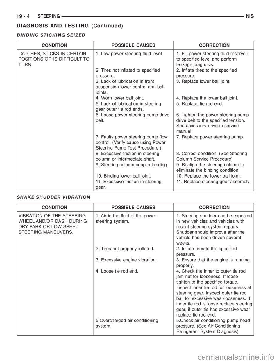
BINDING STICKING SEIZED
SHAKE SHUDDER VIBRATION
CONDITION POSSIBLE CAUSES CORRECTION
CATCHES, STICKS IN CERTAIN
POSITIONS OR IS DIFFICULT TO
TURN.1. Low power steering fluid level. 1. Fill power steering fluid reservoir
to specified level and perform
leakage diagnosis.
2. Tires not inflated to specified
pressure.2. Inflate tires to the specified
pressure.
3. Lack of lubrication in front
suspension lower control arm ball
joints.3. Replace lower ball joint.
4. Worn lower ball joint. 4. Replace the lower ball joint.
5. Lack of lubrication in steering
gear outer tie rod ends.5. Replace tie rod end.
6. Loose power steering pump drive
belt.6. Tighten the power steering pump
drive belt to the specified tension.
See accessory drive in service
manual.
7. Faulty power steering pump flow
control. (Verify cause using Power
Steering Pump Test Procedure.)7. Replace power steering pump.
8. Excessive friction in steering
column or intermediate shaft.8. Correct condition. (See Steering
Column Service Procedure)
9. Steering column coupler binding. 9. Realign the steering column to
eliminate the binding condition.
10. Binding lower ball joint. 10. Replace the lower ball joint.
11. Excessive friction in steering
gear.11. Replace steering gear assembly.
CONDITION POSSIBLE CAUSES CORRECTION
VIBRATION OF THE STEERING
WHEEL AND/OR DASH DURING
DRY PARK OR LOW SPEED
STEERING MANEUVERS.1. Air in the fluid of the power
steering system.1. Steering shudder can be expected
in new vehicles and vehicles with
recent steering system repairs.
Shudder should improve after the
vehicle has been driven several
weeks.
2. Tires not properly inflated. 2. Inflate tires to the specified
pressure.
3. Excessive engine vibration. 3. Ensure that the engine is running
properly.
4. Loose tie rod end. 4. Check the inner to outer tie rod
jam nut for looseness. If loose
tighten to the specified torque.
Inspect inner tie rod for looseness at
steering gear. Inspect outer tie rod
ball for excessive wear/looseness. If
inner tie rod is loose replace steering
gear, if outer tie has excessive wear
replace tie rod end.
5.Overcharged air conditioning
system.5.Check air conditioning pump head
pressure. (See Air Conditioning
Refrigerant System Diagnosis)
19 - 4 STEERINGNS
DIAGNOSIS AND TESTING (Continued)