Page 1192 of 1954

Construction and Function
TCS Control unit
Driving Control
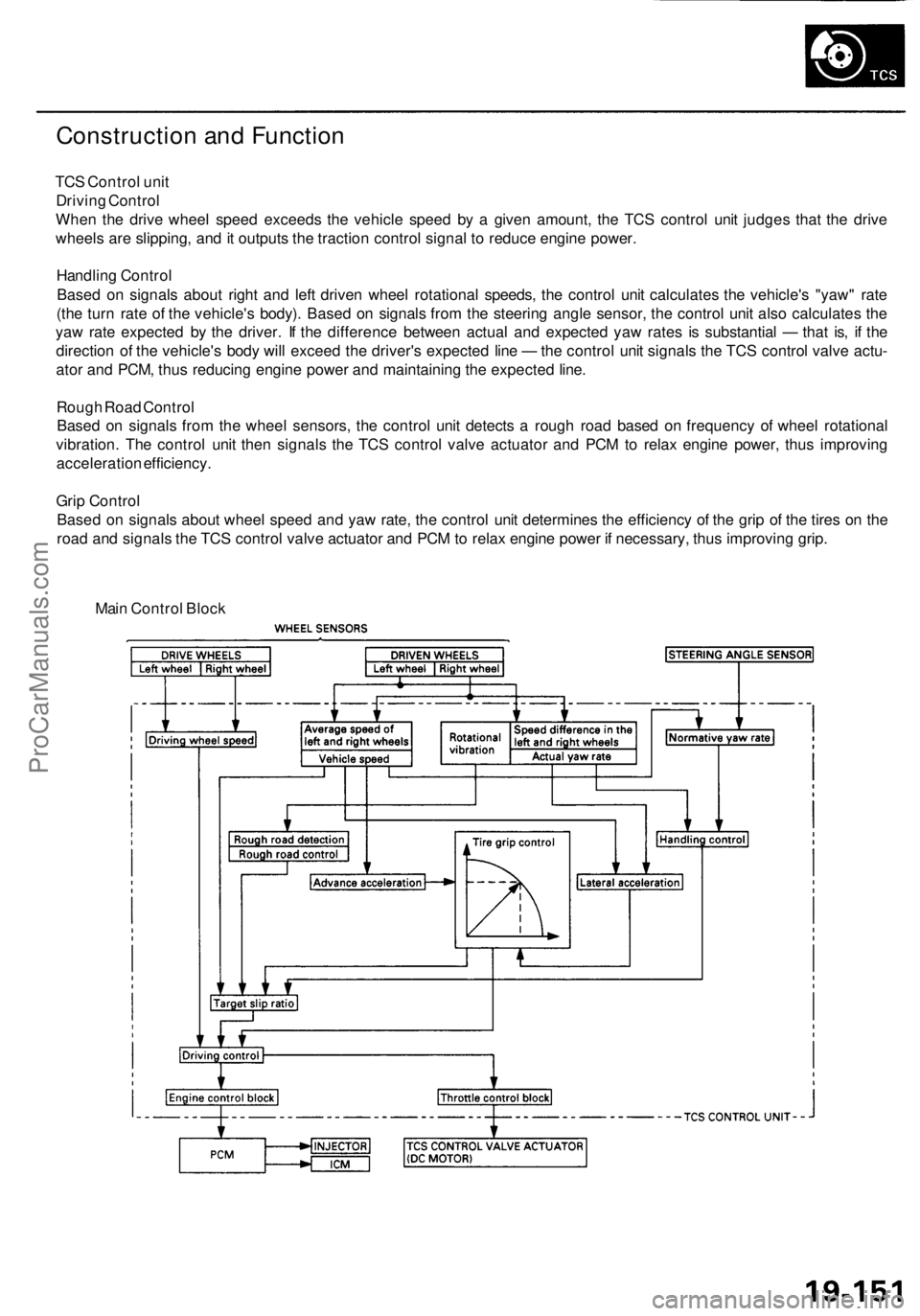
When the drive wheel speed exceeds the vehicle speed by a given amount, the TCS control unit judges that the drive
wheels are slipping, and it outputs the traction control signal to reduce engine power.
Handling Control
Based on signals about right and left driven wheel rotational speeds, the control unit calculates the vehicle's "yaw" rate
(the turn rate of the vehicle's body). Based on signals from the steering angle sensor, the control unit also calculates the
yaw rate expected by the driver. If the difference between actual and expected yaw rates is substantial — that is, if the
direction of the vehicle's body will exceed the driver's expected line — the control unit signals the TCS control valve actu-
ator and PCM, thus reducing engine power and maintaining the expected line.
Rough Road Control
Based on signals from the wheel sensors, the control unit detects a rough road based on frequency of wheel rotational
vibration. The control unit then signals the TCS control valve actuator and PCM to relax engine power, thus improving
acceleration efficiency.
Grip Control
Based on signals about wheel speed and yaw rate, the control unit determines the efficiency of the grip of the tires on the
road and signals the TCS control valve actuator and PCM to relax engine power if necessary, thus improving grip.
Main Control BlockProCarManuals.com
Page 1193 of 1954

System Descriptio n
Fail-Safe Functio n
I f th e contro l uni t detect s a n abnormality , i t shut s th e
tractio n contro l syste m of f an d cause s th e TC S indicato r
light t o com e on . Howeve r i f th e abnormalit y is detecte d
while th e TC S is activated , th e contro l uni t firs t estab -
lishe s th e appropriat e whee l spi n velocity , the n shut s
the syste m down , thu s preventin g excessiv e whee l spin .
Self-Diagnosi s Functio n
If th e contro l uni t detect s a n abnormality , i t record s a
Diagnosti c Troubl e Cod e (DTC ) whic h ca n b e use d t o
diagnos e th e problem . Th e DT C is show n a t th e TC S
indicato r ligh t whe n th e Servic e Chec k connecto r termi -
nal s ar e connecte d wit h th e SC S servic e connector .
Steerin g Angl e Detectio n
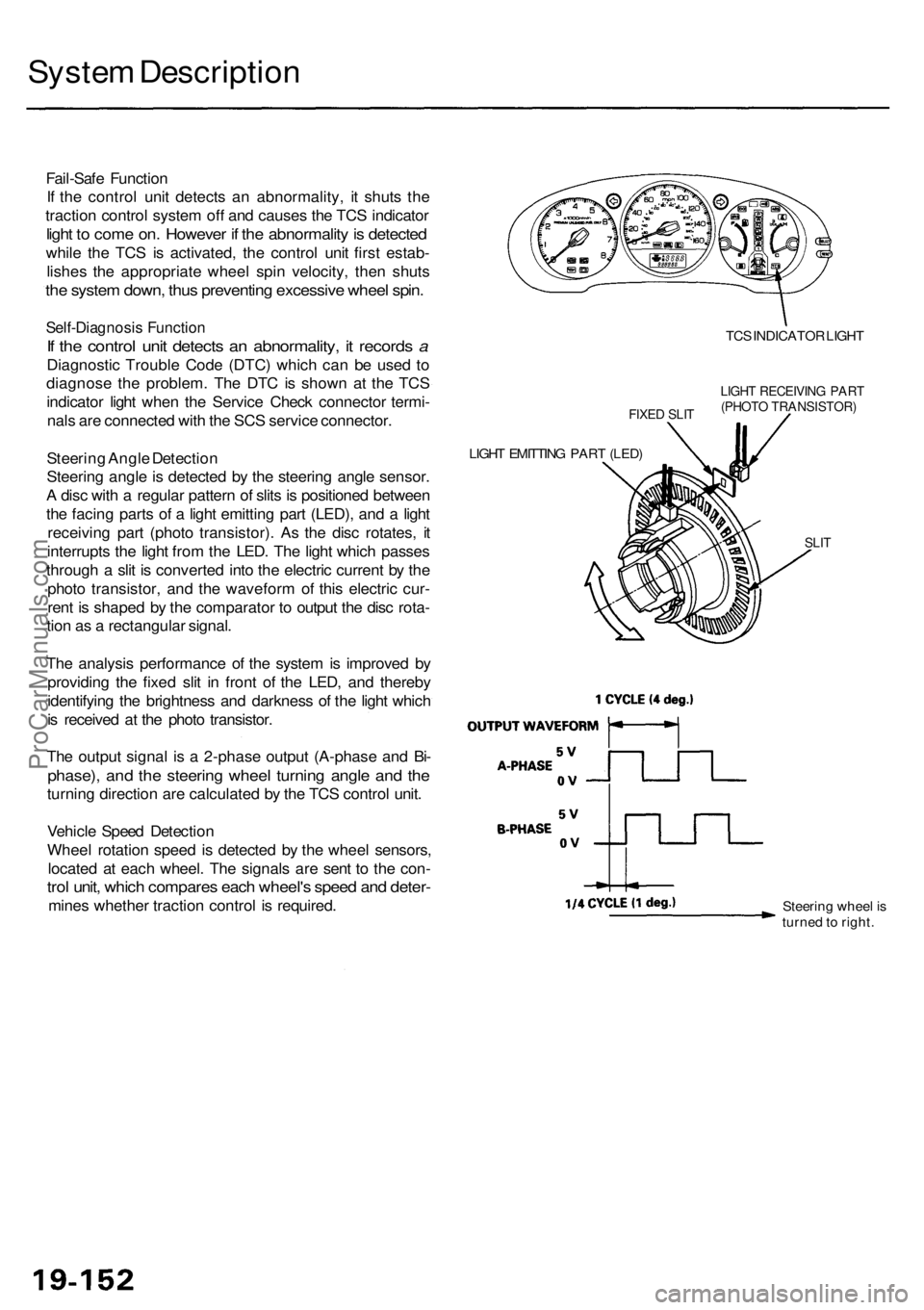
Steerin g angl e is detecte d b y th e steerin g angl e sensor .
A dis c wit h a regula r patter n o f slit s is positione d betwee n
th e facin g part s o f a ligh t emittin g par t (LED) , an d a ligh t
receivin g par t (phot o transistor) . As the dis c rotates , i t
interrupt s th e ligh t fro m th e LED . Th e ligh t whic h passe s
throug h a sli t i s converte d int o th e electri c curren t b y th e
phot o transistor , an d th e wavefor m o f thi s electri c cur -
ren t i s shape d b y th e comparato r t o outpu t th e dis c rota -
tio n a s a rectangula r signal .
Th e analysi s performanc e o f th e syste m is improve d b y
providin g th e fixe d sli t i n fron t o f th e LED , an d thereb y
identifyin g th e brightnes s an d darknes s o f th e ligh t whic h
i s receive d a t th e phot o transistor .
Th e outpu t signa l i s a 2-phas e outpu t (A-phas e an d Bi -
phase) , an d th e steerin g whee l turnin g angl e an d th e
turnin g directio n ar e calculate d b y th e TC S contro l unit .
Vehicl e Spee d Detectio n
Whee l rotatio n spee d i s detecte d b y th e whee l sensors ,
locate d a t eac h wheel . Th e signal s ar e sen t t o th e con -
trol unit , whic h compare s eac h wheel' s spee d an d deter -
mines whethe r tractio n contro l i s required .
FIXED SLI T
LIGH T EMITTIN G PAR T (LED )
TCS INDICATO R LIGH T
LIGHT RECEIVIN G PAR T(PHOT O TRANSISTOR )
SLIT
Steerin g whee l i s
turne d to right .
ProCarManuals.com
Page 1194 of 1954
Engine Output Control
When the TCS is activated, the TCS control unit signals the TCS control valve actuator and PCM. The actuator is linked to
the TCS control valve which is normally returned to the fully open position by the two return springs. Although the throttle
valve is still within the driver's control, the engine output is relaxed by the TCS control valve and PCM to achieve optimum
traction.
TCS CONTROL VALVE SENSOR
TCS CONTROL VALVE
TCS CONTROL VALVE
RETURN SPRINGS
TCS CONTROL VALVE
ACTUATOR (DC MOTOR)
DURING NORMAL DRIVING:
DURING TCS ACTUATION:
TCS CONTROL VALVE
TCS CONTROL VALVE
ACTUATOR (DC MOTOR)
TCS CONTROL VALVE
RETURN SPRINGS
TCS ACTUATION SIGNAL
FROM TCS CONTROL UNITProCarManuals.com
Page 1207 of 1954

Troubleshooting
Steering Angl e Senso r
Diagnosti c Troubl e Cod e (DTC ) 2-1 : Steerin g Angl e Senso r Diagnosi s
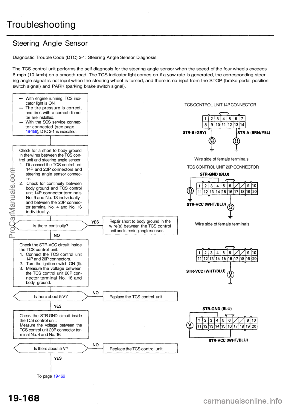
The TC S contro l uni t perform s th e self-diagnosi s fo r th e steerin g angl e senso r whe n th e spee d o f th e fou r wheel s exceed s
6 mp h (1 0 km/h ) o n a smoot h road . Th e TC S indicato r ligh t come s o n if a ya w rat e is generated , th e correspondin g steer -
ing angl e signa l i s no t inpu t whe n th e steerin g whee l i s turned , an d ther e is n o inpu t fro m th e STO P (brak e peda l positio n
switch signal ) an d PAR K (parkin g brak e switc h signal) .
With engin e running , TC S indi -
cato r ligh t i s ON .
Th e tir e pressur e i s correct ,
an d tire s wit h a correc t diame -
te r ar e installed .
Wit h th e SC S servic e connec -
to r connecte d (se e pag e
19-159 ), DT C 2- 1 is indicated .
Chec k fo r a shor t t o bod y groun d
i n th e wire s betwee n th e TC S con -
tro l uni t an d steerin g angl e sensor :
1 . Disconnec t th e TC S contro l uni t
14P an d 20 P connector s an dsteerin g angl e senso r connec -tor.2. Chec k fo r continuit y betwee n
bod y groun d an d TC S contro l
unit 14 P connecto r terminal sNo. 9 an d No . 1 3 individuall yand betwee n th e 20 P connec -
to r termina l No . 4 an d No . 1 6
individually .
Is ther e continuity ?
Chec k th e STR-VC C circui t insid e
th e TC S contro l unit :
1 . Connec t th e TC S contro l uni t
14 P an d 20 P connectors .
2 . Tur n th e ignitio n switc h O N (II) .
3. Measur e th e voltag e betwee nthe TC S contro l uni t 20 P con -necto r termina l No . 1 6 an dbod y ground .
Is ther e abou t 5 V ?
Chec k th e STR-GN D circui t insid e
th e TC S contro l unit :
Measur e th e voltag e betwee n th e
TC S contro l uni t 20 P connecto r ter -
mina l No . 4 an d No . 16 .
Is ther e abou t 5 V ?
T o pag e 19-16 9 TC
S CONTRO L UNI T 14 P CONNECTO R
Wir e sid e o f femal e terminal s
TC S CONTRO L UNI T 20 P CONNECTO R
Repair shor t t o bod y groun d in th ewire(s ) betwee n th e TC S contro l
uni t an d steerin g angl e sensor . Wir
e sid e o f femal e terminal s
Replac e th e TC S contro l unit .
Replac e th e TC S contro l unit .
ProCarManuals.com
Page 1214 of 1954
![ACURA RL KA9 1996 Service Repair Manual
PGM-FI DTC: 36 [TC-FC signal (High-Low check)]
Check for a short to body ground
in the TC-FC circuit:
1. Disconnect the PCM connec-
tor C (12P) and TCS control
unit 20P connectors.
2. Check for ACURA RL KA9 1996 Service Repair Manual
PGM-FI DTC: 36 [TC-FC signal (High-Low check)]
Check for a short to body ground
in the TC-FC circuit:
1. Disconnect the PCM connec-
tor C (12P) and TCS control
unit 20P connectors.
2. Check for](/manual-img/32/56992/w960_56992-1213.png)
PGM-FI DTC: 36 [TC-FC signal (High-Low check)]
Check for a short to body ground
in the TC-FC circuit:
1. Disconnect the PCM connec-
tor C (12P) and TCS control
unit 20P connectors.
2. Check for continuity between
the TCS control unit 20P con-
nector terminal No. 14 and
body ground.
TCS CONTROL UNIT 20P CONNECTOR
Is there continuity?
Repair short to body ground in
the wire between the PCM and
TCS control unit.
Wire side of female terminals
TCS IS NOT TCS IS
FUNCTIONING FUNCTIONING
NOTE: Use the 10 V range or a similar
range in an analog tester.
Is there about 4.5 V when TCS is
not functioning?
Check for loose TCS control unit
connector. If necessary, substi-
tute a known-good TCS control
unit and recheck.
Check for an open in the TC-FC
circuit:
Measure the voltage between the
PCM connector C (12P) terminal
No. 10 and body ground.
NOTE: Use the 10 V range or a similar
range in an analog tester.
TCS IS NOT TCS IS
FUNCTIONING FUNCTIONING
PCM CONNECTOR C (12P)
Is there about 4.5 V when TCS is
not functioning?
Repair open in the wire between
the TCS control unit and PCM.
Wire side of female terminals
Check for loose PCM connectors.
If necessary, substitute a known-
good PCM and recheck.
Check the TCS control unit:
1. Connect the TCS control unit
20P connector.
2. Turn the ignition switch ON
(II).
3. Measure the voltage between
the TCS control unit 20P con-
nector terminal No. 14 and
body ground.ProCarManuals.com
Page 1425 of 1954
Description
Fan Contro l Uni t
The fa n contro l uni t make s calculation s base d o n signal s fro m th e radiato r fa n contro l sensor . I t the n control s th e opera -
tio n o f th e radiato r fan , condense r fa n an d A/ C system .
ON
OF F
172° F (78°C )
183°F (84°C )Whe
n engin e coolan t temperatur e is abov e 183° F (84°C) ,
th e fa n contro l uni t turn s Tr 1 ON , an d th e radiato r fa n
(Low ) an d condense r fa n run s (Low) .
ON
OF F
183° F (84°C )
When engin e coolan t temperatur e is abov e 194° F (90°C) ,
th e fa n contro l uni t turn s Tr 2 ON , an d th e radiato r fa n
(High ) runs , an d th e condense r fa n (High ) goe s on .
194° F (90°C )
ON
OF F
225° F (107°C )When engin e coolan t temperatur e is abov e 228° F (109°C) ,
the fa n contro l uni t turn s Tr 3 OFF , an d stop s th e A/ C com -
pressor .
228°F (109°C )
*1: CONDENSE R FA N RELA Y*2: RADIATO R FA N RELA Y*3: RADIATO R FA N MAI N RELA Y
RED/WH T
ProCarManuals.com
Page 1512 of 1954
Relay an d Contro l Uni t Location s
Dashboar d
IMMOBILIZE R PGM-F I MAI N CRUIS E CONTRO L
CONTRO L UNI T RELA Y STEERIN G COLUM N CONTRO L UNI T UNI T
MULTIPLE X
CONTROL UNI T(DRIVER'S )
UNDER-DAS H
FUSE/RELA Y BO X
STARTE R CU T RELA Y
SRS UNI T
POWE R WINDO WRELAY
TURN SIGNAL /HAZARD RELA Y
ProCarManuals.com
Page 1536 of 1954

*: Yo u ca n als o tes t th e switc h b y usin g th e self-diagnosi s functio n (mod e 2) . (Se e pag e 23-252 .)
UNDER-DAS HFUSE/RELAY BO X
TUR N SIGNAL/HAZAR D RELA Y
Inpu t Test , pag e 23-13 4
COMBINATIO
N LIGH T SWITCH *
Test , pag e 23-12 1
DAS
H LIGHT S BRIGHTNES S
CONTROLLER *Controller Test ,
pag e 23-25 6
Lightin g Syste m
Componen t Locatio n Inde x
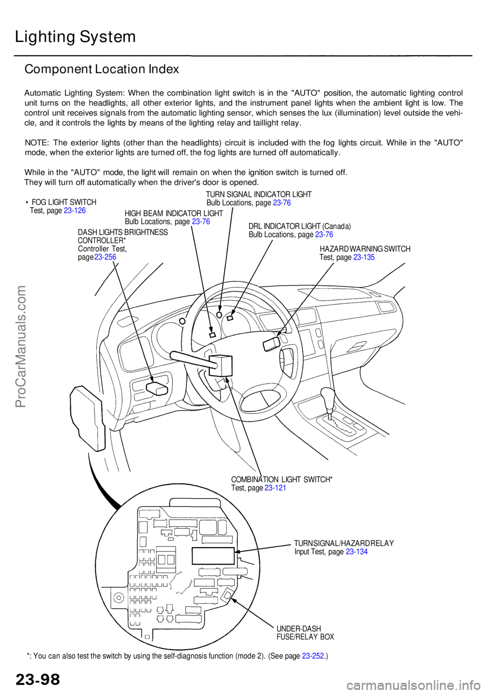
Automati c Lightin g System : Whe n th e combinatio n ligh t switc h i s i n th e "AUTO " position , th e automati c lightin g contro l
uni t turn s o n th e headlights , al l othe r exterio r lights , an d th e instrumen t pane l light s whe n th e ambien t ligh t i s low . Th e
contro l uni t receive s signal s fro m th e automati c lightin g sensor , whic h sense s th e lu x (illumination ) leve l outsid e th e vehi -
cle , an d it control s th e light s b y mean s o f th e lightin g rela y an d tailligh t relay .
NOTE : Th e exterio r light s (othe r tha n th e headlights ) circui t i s include d wit h th e fo g light s circuit . Whil e i n th e "AUTO "
mode , whe n th e exterio r light s ar e turne d off , th e fo g light s ar e turne d of f automatically .
Whil e in th e "AUTO " mode , th e ligh t wil l remai n o n whe n th e ignitio n switc h i s turne d off .
The y wil l tur n of f automaticall y whe n th e driver' s doo r i s opened .
• FO G LIGH T SWITC H
Test , pag e 23-12 6
HIGH BEA M INDICATO R LIGH T
Bul b Locations , pag e 23-7 6
TUR
N SIGNA L INDICATO R LIGH T
Bul b Locations , pag e 23-7 6
DR L INDICATO R LIGH T (Canada )
Bul b Locations , pag e 23-7 6
HAZAR D WARNIN G SWITC H
Test , pag e 23-13 5
ProCarManuals.com