1996 ACURA RL KA9 turn signal
[x] Cancel search: turn signalPage 1547 of 1954

Headlights
Combinatio n Ligh t Switc h
Replacemen t
1. Remov e th e dashboar d lowe r cove r (se e sectio n 20 ).
2 . Remove the steering column covers (see
section 17 ).
3 . Disconnec t th e 14 P connecto r fro m th e combinatio n
ligh t switch , the n remov e th e tw o screw s an d th e
switch .
4 . Instal l th e combinatio n ligh t switc h i n th e revers e
orde r o f removal .
COMBINATIO N LIGH T SWITC H
14
P CONNECTO R
Replacemen t
CAUTION: Headlight s becom e ver y ho t i n use ; d o no t
touc h the m o r th e attachin g hardwar e immediatel y
afte r the y hav e bee n turne d off .
1 . Remov e th e fron t bumpe r an d fron t bumpe r uppe r
bea m (se e sectio n 20 ).
2 . Disconnec t th e connectors .
3 . Remov e th e fou r mountin g bolts , the n remov e th e
headligh t assembly .
HEADLIGH T
ASSEMBL Y
'9 6 - 9 8 models :
HEADLIGHT : 60/5 5 W
FRON T TUR N SIGNA L LIGHT : 2 1 W
FRON T PARKIN G LIGHT : 5 W x 2
FRON T FO G LIGHT : 5 5 W
SID E MARKE R LIGHT : 5 W
'9 9 - 0 1 models :
HEADLIGH T LO W BEAM : 3 5 W
HEADLIGH T HIG H BEAM : 5 5 W
FRON T TUR N SIGNAL/PARKIN G LIGHT : 27/ 8 W
SID E MARKE R LIGHT : 5 W
4. Instal l th e headligh t i n th e revers e orde r o f removal .
5 . Afte r replacement , adjus t th e headlight s t o loca l
requirements .
ProCarManuals.com
Page 1556 of 1954
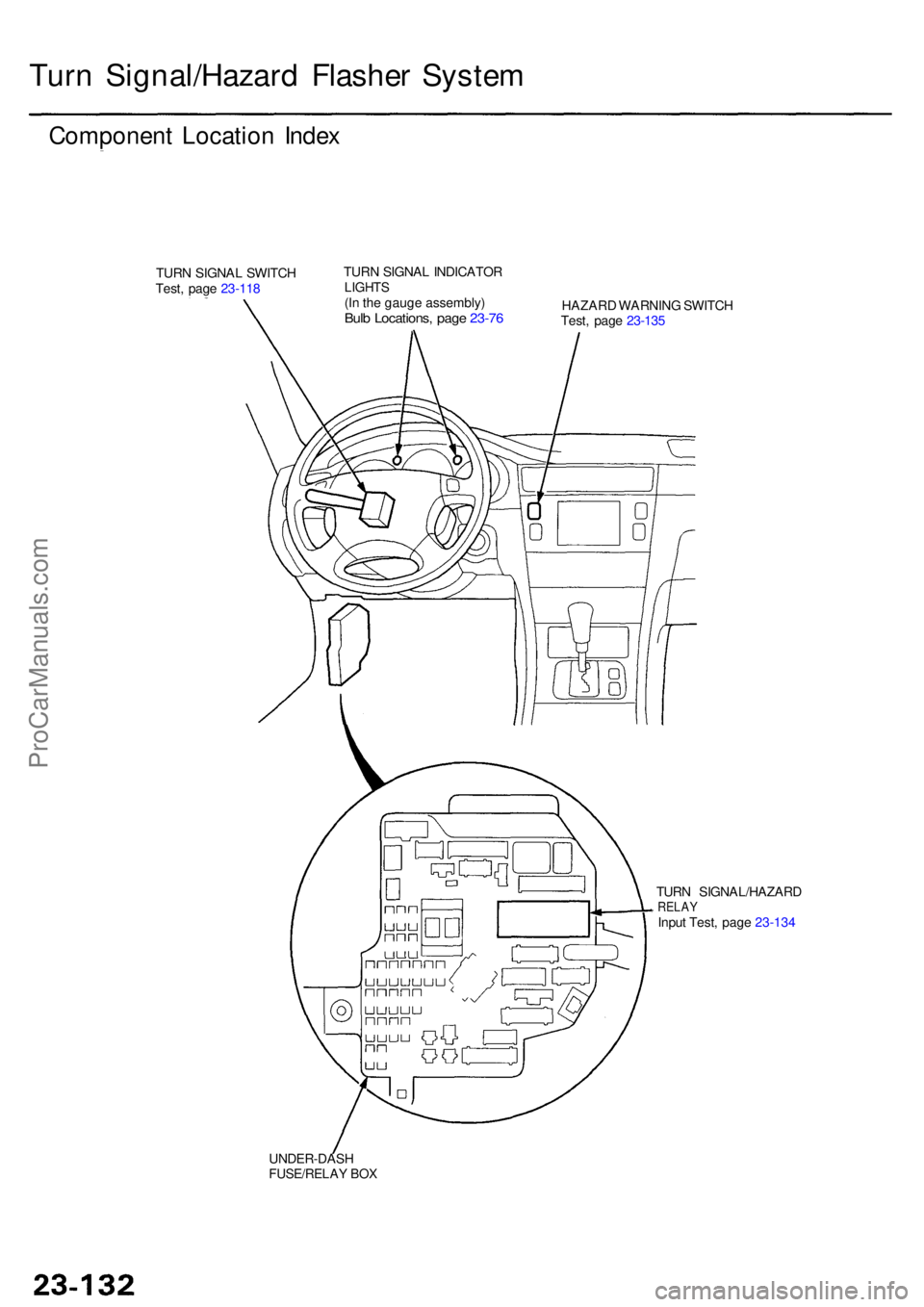
Turn Signal/Hazar d Flashe r Syste m
Componen t Locatio n Inde x
TURN SIGNA L SWITC H
Test , pag e 23-11 8 TUR
N SIGNA L INDICATO RLIGHTS(In th e gaug e assembly )Bulb Locations , pag e 23-7 6HAZAR D WARNIN G SWITC H
Test , pag e 23-13 5
TUR N SIGNAL/HAZAR D
RELAYInput Test , pag e 23-13 4
UNDER-DAS H
FUSE/RELAY BO X
ProCarManuals.com
Page 1557 of 1954
Turn Signal/Hazar d Flashe r Syste m
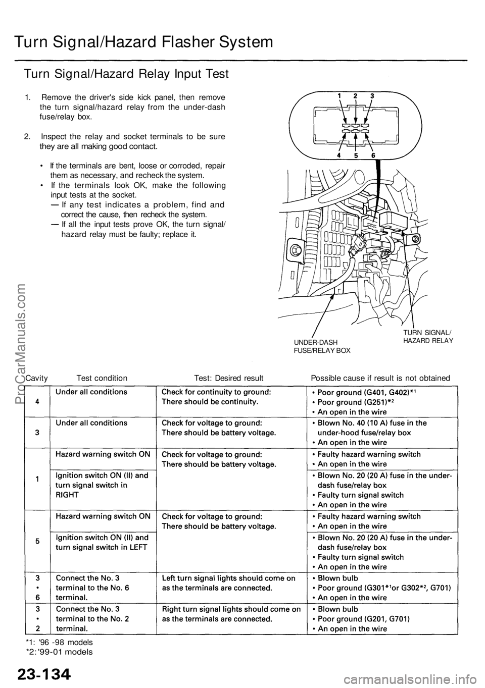
Turn Signal/Hazar d Rela y Inpu t Tes t
1. Remov e th e driver' s sid e kic k panel , the n remov e
th e tur n signal/hazar d rela y fro m th e under-das h
fuse/rela y box .
2 . Inspec t th e rela y an d socke t terminal s t o b e sur e
they ar e al l makin g goo d contact .
• I f th e terminal s ar e bent , loos e o r corroded , repai r
the m as necessary , an d rechec k th e system .
• I f th e terminal s loo k OK , mak e th e followin g
inpu t test s a t th e socket .
If an y tes t indicate s a problem , fin d an d
correc t th e cause , the n rechec k th e system .
I f al l th e inpu t test s prov e OK , th e tur n signal /
hazar d rela y mus t b e faulty ; replac e it .
UNDER-DAS HFUSE/RELAY BO X
TUR N SIGNAL /HAZARD RELA Y
Cavity Tes t conditio n Test : Desire d resul t Possibl e caus e if resul t i s no t obtaine d
*1 : '9 6 -9 8 model s
*2: '99-0 1 model s
ProCarManuals.com
Page 1588 of 1954
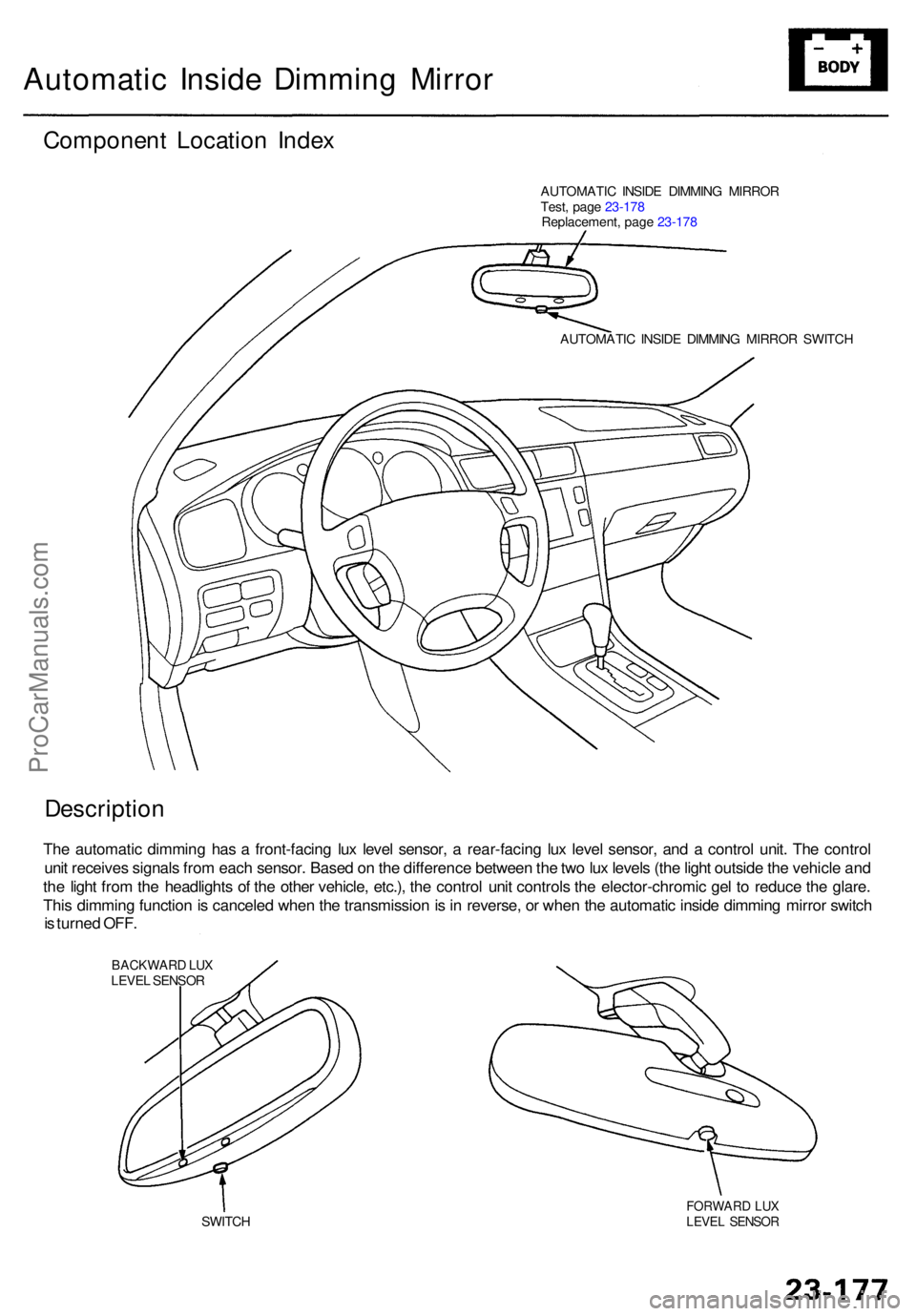
Automatic Insid e Dimmin g Mirro r
Componen t Locatio n Inde x
AUTOMATI C INSID E DIMMIN G MIRRO R
Test , pag e 23-17 8
Replacement , pag e 23-17 8
AUTOMATI C INSID E DIMMIN G MIRRO R SWITC H
Descriptio n
The automati c dimmin g ha s a front-facin g lu x leve l sensor , a rear-facin g lu x leve l sensor , an d a contro l unit . Th e contro l
uni t receive s signal s fro m eac h sensor . Base d o n th e differenc e betwee n th e tw o lu x level s (th e ligh t outsid e th e vehicl e an d
th e ligh t fro m th e headlight s o f th e othe r vehicle , etc.) , th e contro l uni t control s th e elector-chromi c ge l t o reduc e th e glare .
Thi s dimmin g functio n is cancele d whe n th e transmissio n is in reverse , o r whe n th e automati c insid e dimmin g mirro r switc h
i s turne d OFF .
BACKWAR D LU XLEVE L SENSO R
SWITC H
FORWAR D LU XLEVE L SENSO R
ProCarManuals.com
Page 1593 of 1954
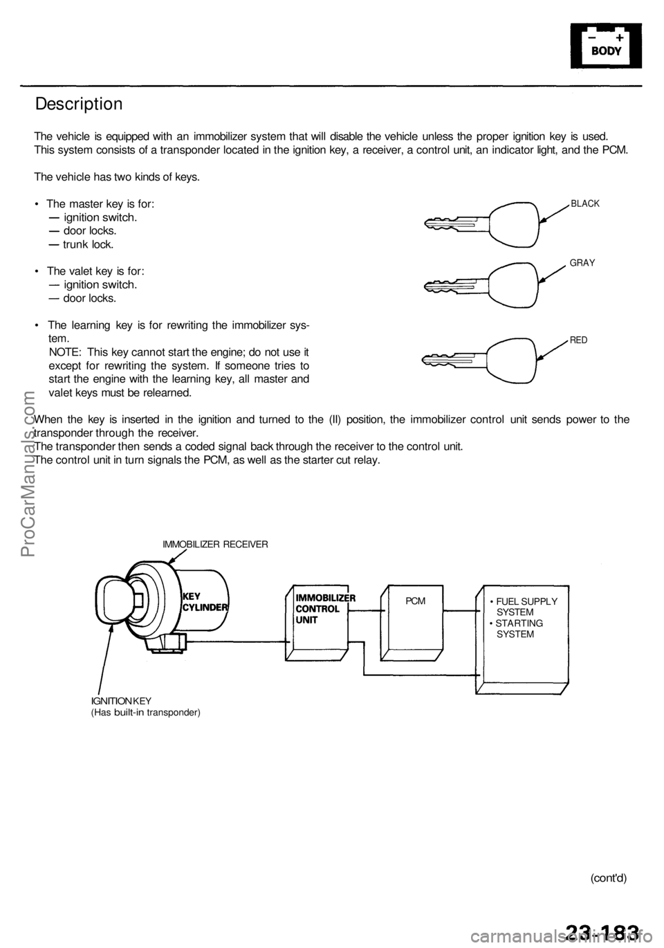
Description
The vehicl e is equippe d wit h a n immobilize r syste m tha t wil l disabl e th e vehicl e unles s th e prope r ignitio n ke y i s used .
Thi s syste m consist s o f a transponde r locate d in th e ignitio n key , a receiver , a contro l unit , a n indicato r light , an d th e PCM .
Th e vehicl e ha s tw o kind s o f keys .
• Th e maste r ke y i s for :
ignitio n switch .
door locks .
trunk lock .
• Th e vale t ke y i s for :
ignitio n switch .
door locks .
• Th e learnin g ke y i s fo r rewritin g th e immobilize r sys -
tem.
NOTE : Thi s ke y canno t star t th e engine ; d o no t us e it
excep t fo r rewritin g th e system . I f someon e trie s t o
star t th e engin e wit h th e learnin g key , al l maste r an d
vale t key s mus t b e relearned .
Whe n th e ke y i s inserte d i n th e ignitio n an d turne d t o th e (II ) position , th e immobilize r contro l uni t send s powe r t o th e
transponde r throug h th e receiver .
Th e transponde r the n send s a code d signa l bac k throug h th e receive r t o th e contro l unit .
Th e contro l uni t i n tur n signal s th e PCM , a s wel l a s th e starte r cu t relay .
IMMOBILIZE R RECEIVE R
IGNITION KEY(Ha s built-i n transponder ) •
FUE L SUPPL Y
SYSTE M
• STARTIN G
SYSTEM
PCM
BLAC K
GRAY
RED
(cont'd )
ProCarManuals.com
Page 1594 of 1954
Immobilizer Syste m
Descriptio n (cont'd )
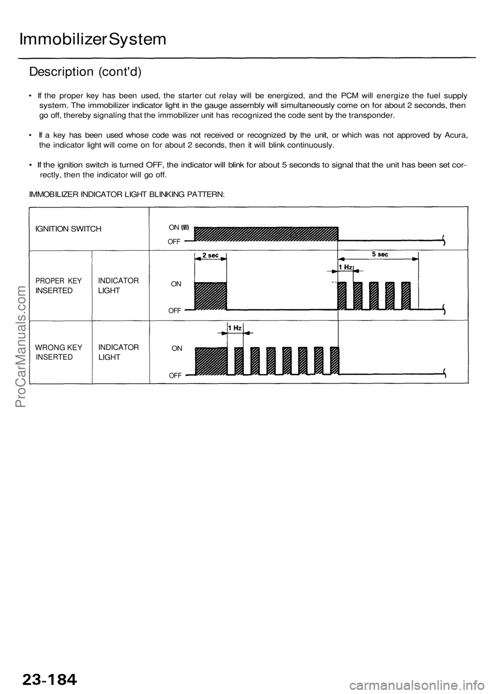
• I f th e prope r ke y ha s bee n used , th e starte r cu t rela y wil l b e energized , an d th e PC M wil l energiz e th e fue l suppl y
system . Th e immobilize r indicato r ligh t i n th e gaug e assembl y wil l simultaneousl y com e o n fo r abou t 2 seconds , the n
go off , thereb y signalin g tha t th e immobilize r uni t ha s recognize d th e cod e sen t b y th e transponder .
• I f a ke y ha s bee n use d whos e cod e wa s no t receive d o r recognize d b y th e unit , o r whic h wa s no t approve d b y Acura ,
th e indicato r ligh t wil l com e o n fo r abou t 2 seconds , the n it wil l blin k continuously .
• I f th e ignitio n switc h is turne d OFF , th e indicato r wil l blin k fo r abou t 5 second s to signa l tha t th e uni t ha s bee n se t cor -
rectly , the n th e indicato r wil l g o off .
IMMOBILIZE R INDICATO R LIGH T BLINKIN G PATTERN :
WRONG KE Y
INSERTE D
PROPER KE Y
INSERTE D
IGNITION SWITC H
INDICATO R
LIGHT
INDICATO R
LIGHT
ON
OF F
ON
OF F
ON
OF F
ProCarManuals.com
Page 1645 of 1954
System Function s
• Multiple x Contro l Syste m (Multiple x function , Wak e up/slee p function , Fail-saf e function , Self-diagnosi s function* )
* : Self-diagnosi s functio n mod e 1 is th e self-diagnosi s fo r th e multiple x contro l system .
Self-diagnosi s functio n mod e 2 is th e failur e diagnosi s fo r th e inpu t lin e o f eac h system .
• Integrate d Contro l Syste m (Engin e oi l pressur e indicato r flashe r circuit , Key-i n reminde r circuit , Light-o n reminde r circuit ,
Sea t bel t reminde r circuit )
• Das h Light s Brightnes s Contro l
• Entr y Ligh t Contro l Syste m
• Rea r Windo w Defogge r
• Trun k li d Opene r
• Powe r Doo r Lock s (wit h keyles s entr y system )
• Powe r Windo w (wit h key-of f timer operation )
• Wiper/washer s (wit h spee d responden t intermitten t wiper )
• Securit y Alar m Syste m
• Interloc k Syste m (se e sectio n 14 )
Multiple x Communicatio n Syste m
Multiple x Communicatio n Function s
• T o reduc e th e numbe r o f wir e harnesses , digita l signal s ar e sen t vi a share d multiple x communicatio n line s rather than
sendin g norma l electrica l signal s throug h individua l wires .
• Th e inpu t signal s fro m eac h switc h ar e converte d t o digita l signal s a t th e centra l processin g uni t (CPU) . Th e digita l
signal s ar e sen t fro m th e transmitte r uni t t o th e receive r uni t a s seria l signals .
• Th e transmitte d signa l i s converte d t o a switc h signa l a t th e receive r unit , an d it operate s th e relate d component .
• Ther e ar e exclusiv e communicatio n line s betwee n eac h o f th e multiple x contro l units :
Door Driver' s (fro m th e doo r t o th e driver' s multiple x contro l units ) Wir e color : BRN/YE L
Driver's Passenger' s (fro m th e driver' s t o th e passenger' s multiple x contro l units ) Wir e color : BRN/WH T
Passenger' s Driver' s (fro m th e passenger' s t o th e driver' s multiple x contro l units ) Wir e color : RED/YE L
• Th e contro l unit s alway s communicat e vi a thes e line s whe n th e syste m is operating , an d the y sto p communicatin g
whe n th e syste m is OFF .
Wake-u p an d Slee p Function s
• Th e multiple x contro l syste m ha s "wake-up " an d "sleep " function s t o decreas e parasiti c dra w o n th e batter y whe n th e
ignitio n switc h is OFF .
• I n th e slee p mode , th e multiple x contro l uni t stop s th e function s (communicatio n an d CP U control ) whe n i t i s no t nec -
essar y fo r th e syste m to operate .
• A s soo n a s an y operatio n i s don e (fo r example , a doo r i s unlocked) , th e relate d contro l uni t i n th e slee p mod e wake s u p
an d begin s t o functio n a t once . Thi s contro l uni t als o send s a wake-u p signa l t o th e othe r contro l unit s vi a th e commu -
nicatio n lines .
• Whe n th e ignitio n switc h i s turne d OFF , ther e i s abou t a 30 secon d dela y befor e th e contro l unit s g o fro m th e wake-u p
mod e t o th e slee p mode .
• I f an y doo r i s open , th e slee p mod e wil l no t function .
Fail-safe Function s
• T o preven t imprope r operation , th e multiple x contro l syste m ha s a fail-saf e function . I n th e fail-saf e mode , th e outpu t
signa l i s fixe d whe n an y par t o f th e syste m malfunction s (fo r example , a fault y contro l uni t o r communicatio n line) .
• Eac h contro l uni t ha s a hardwar e fail-saf e functio n tha t fixe s th e outpu t signa l whe n ther e i s an y CP U malfunctio n an d
a softwar e fail-saf e functio n tha t ignore s th e signa l fro m th e malfunctionin g contro l uni t an d allow s th e syste m to
operat e normally .
ProCarManuals.com
Page 1731 of 1954
Description
Navigation Functio n (cont'd )
Yaw Rat e Senso r
Th e ya w rat e senso r detect s th e directio n chang e (angula r speed ) o f th e vehicle . Th e senso r i s a n oscillatio n gyr o buil t int o
the navigatio n unit .
Senso r Elemen t Structur e
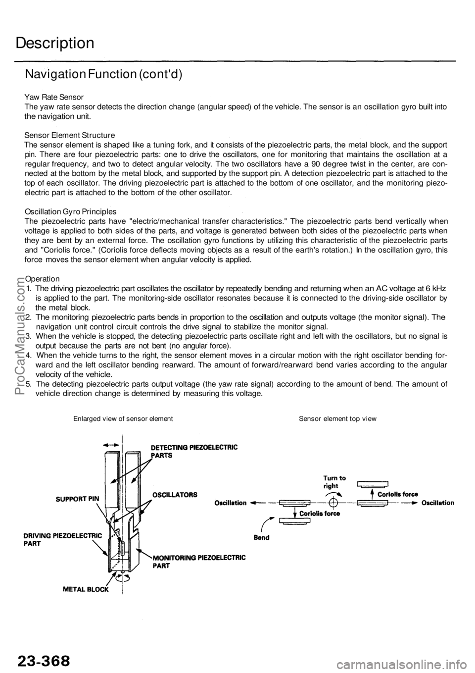
Th e senso r elemen t i s shape d lik e a tunin g fork , an d it consist s o f th e piezoelectri c parts , th e meta l block , an d th e suppor t
pin . Ther e ar e fou r piezoelectri c parts : on e t o driv e th e oscillators , on e fo r monitorin g tha t maintain s th e oscillatio n a t a
regula r frequency , an d tw o t o detec t angula r velocity . Th e tw o oscillator s hav e a 90 degre e twis t i n th e center , ar e con -
necte d a t th e botto m b y th e meta l block , an d supporte d b y th e suppor t pin . A detectio n piezoelectri c par t i s attache d to th e
to p o f eac h oscillator . Th e drivin g piezoelectri c par t i s attache d t o th e botto m o f on e oscillator , an d th e monitoring piezo-
electri c par t i s attache d t o th e botto m o f th e othe r oscillator .
Oscillatio n Gyr o Principle s
Th e piezoelectri c part s hav e "electric/mechanica l transfe r characteristics. " Th e piezoelectri c part s ben d verticall y whe n
voltag e is applie d t o bot h side s o f th e parts , an d voltag e is generate d betwee n bot h side s o f th e piezoelectri c part s whe n
the y ar e ben t b y a n externa l force . Th e oscillatio n gyr o function s b y utilizin g thi s characteristi c o f th e piezoelectri c part s
an d "Corioli s force. " (Corioli s forc e deflect s movin g object s a s a resul t o f th e earth' s rotation. ) I n th e oscillation gyro, thi s
forc e move s th e senso r elemen t whe n angula r velocit y is applied .
Operatio n
1. Th e drivin g piezoelectri c par t oscillate s th e oscillato r b y repeatedl y bendin g an d returnin g whe n a n A C voltag e a t 6 kH z
is applie d t o th e part . Th e monitoring-sid e oscillato r resonate s becaus e it i s connecte d t o th e driving-sid e oscillato r b y
th e meta l block .
2. Th e monitorin g piezoelectri c part s bend s in proportio n to th e oscillatio n an d output s voltag e (th e monito r signal) . Th e
navigatio n uni t contro l circui t control s th e driv e signa l t o stabiliz e th e monito r signal .
3 . Whe n th e vehicl e is stopped , th e detectin g piezoelectri c part s oscillat e righ t an d lef t wit h th e oscillators , bu t n o signa l i s
outpu t becaus e th e part s ar e no t ben t (n o angula r force) .
4 . Whe n th e vehicl e turn s t o th e right , th e senso r elemen t move s i n a circula r motio n wit h th e righ t oscillato r bendin g for -
war d an d th e lef t oscillato r bendin g rearward . Th e amoun t o f forward/rearwar d ben d varie s accordin g t o th e angula r
velocity o f th e vehicle .
5. Th e detectin g piezoelectri c part s outpu t voltag e (th e ya w rat e signal ) accordin g t o th e amoun t o f bend . Th e amoun t o f
vehicl e directio n chang e is determine d b y measurin g thi s voltage .
Enlarged vie w o f senso r elemen t Senso r elemen t to p vie w
ProCarManuals.com