1996 ACURA RL KA9 stop start
[x] Cancel search: stop startPage 738 of 1954

Position
As the engine turns, the ATF pump also starts to operate. Automatic transmission fluid (ATF) is drawn from (99) and dis-
charged into (1). Then, ATF flowing from the ATF pump becomes the line pressure (1). The line pressure (1) is regulated
by the regulator valve. The torque converter inlet pressure (92) enters (94) of the torque converter through the lock-up
shift valve and discharges into (90). The torque converter check valve prevents the torque converter pressure from rising.
Under this condition, the hydraulic pressure is not applied to the clutches as the manual valve stops line pressure (1).
NOTE:
• When used, "left" or "right" indicates direction on the hydraulic circuit.
• The hydraulic circuit is for '96 - '98 models. On '99 - 01 models, the 2nd accumulator is different.ProCarManuals.com
Page 817 of 1954

Pressure Testing
(cont'd)
6. Disconnect the transmission sub-harness connector (14P).
7. Start the engine, and run it at 2,000 rpm.
Terminal side of female terminals
8. Shift to the or position, and measure line pressure at the fully opened throttle condition.
9. Connect battery voltage to the A/T clutch pressure control solenoid valve terminals of the transmission sub-harness
connector as shown.
10. Measure line pressure at the fully closed throttle condition.
If line pressure is out of specification, check and repair probable cause in the table below.
11. Stop the engine, and connect the transmission sub-harness connector (14P).
12. Disconnect the special tool from line pressure inspection hole, and connect the special tool to each inspection hole.
13. Start the engine, and run it as 2,000 rpm.
TRANSMISSION SUB-HARNESS
CONNECTOR (14P)ProCarManuals.com
Page 1084 of 1954
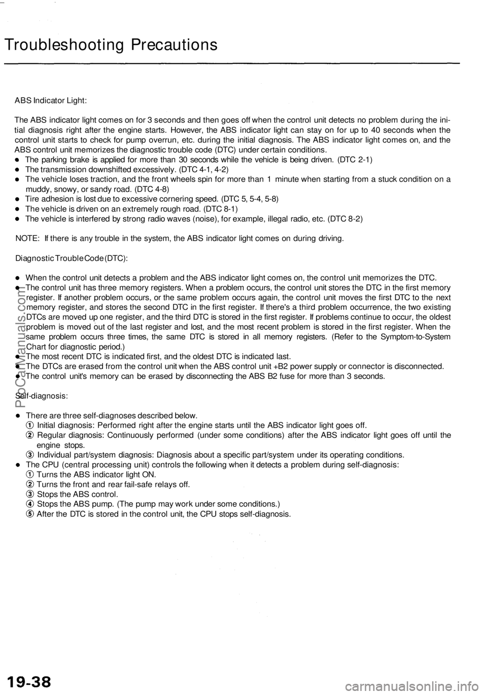
Troubleshooting Precautions
ABS Indicator Light:
The ABS indicator light comes on for 3 seconds and then goes off when the control unit detects no problem during the ini-
tial diagnosis right after the engine starts. However, the ABS indicator light can stay on for up to 40 seconds when the
control unit starts to check for pump overrun, etc. during the initial diagnosis. The ABS indicator light comes on, and the
ABS control unit memorizes the diagnostic trouble code (DTC) under certain conditions.
The parking brake is applied for more than 30 seconds while the vehicle is being driven. (DTC 2-1)
The transmission downshifted excessively. (DTC 4-1, 4-2)
The vehicle loses traction, and the front wheels spin for more than 1 minute when starting from a stuck condition on a
muddy, snowy, or sandy road. (DTC 4-8)
Tire adhesion is lost due to excessive cornering speed. (DTC 5, 5-4, 5-8)
The vehicle is driven on an extremely rough road. (DTC 8-1)
The vehicle is interfered by strong radio waves (noise), for example, illegal radio, etc. (DTC 8-2)
NOTE: If there is any trouble in the system, the ABS indicator light comes on during driving.
Diagnostic Trouble Code (DTC):
When the control unit detects a problem and the ABS indicator light comes on, the control unit memorizes the DTC.
The control unit has three memory registers. When a problem occurs, the control unit stores the DTC in the first memory
register. If another problem occurs, or the same problem occurs again, the control unit moves the first DTC to the next
memory register, and stores the second DTC in the first register. If there's a third problem occurrence, the two existing
DTCs are moved up one register, and the third DTC is stored in the first register. If problems continue to occur, the oldest
problem is moved out of the last register and lost, and the most recent problem is stored in the first register. When the
same problem occurs three times, the same DTC is stored in all memory registers. (Refer to the Symptom-to-System
Chart for diagnostic period.)
The most recent DTC is indicated first, and the oldest DTC is indicated last.
The DTCs are erased from the control unit when the ABS control unit +B2 power supply or connector is disconnected.
The control unit's memory can be erased by disconnecting the ABS B2 fuse for more than 3 seconds.
Self-diagnosis:
There are three self-diagnoses described below.
Initial diagnosis: Performed right after the engine starts until the ABS indicator light goes off.
Regular diagnosis: Continuously performed (under some conditions) after the ABS indicator light goes off until the
engine stops.
Individual part/system diagnosis: Diagnosis about a specific part/system under its operating conditions.
The CPU (central processing unit) controls the following when it detects a problem during self-diagnosis:
Turns the ABS indicator light ON.
Turns the front and rear fail-safe relays off.
Stops the ABS control.
Stops the ABS pump. (The pump may work under some conditions.)
After the DTC is stored in the control unit, the CPU stops self-diagnosis.ProCarManuals.com
Page 1104 of 1954
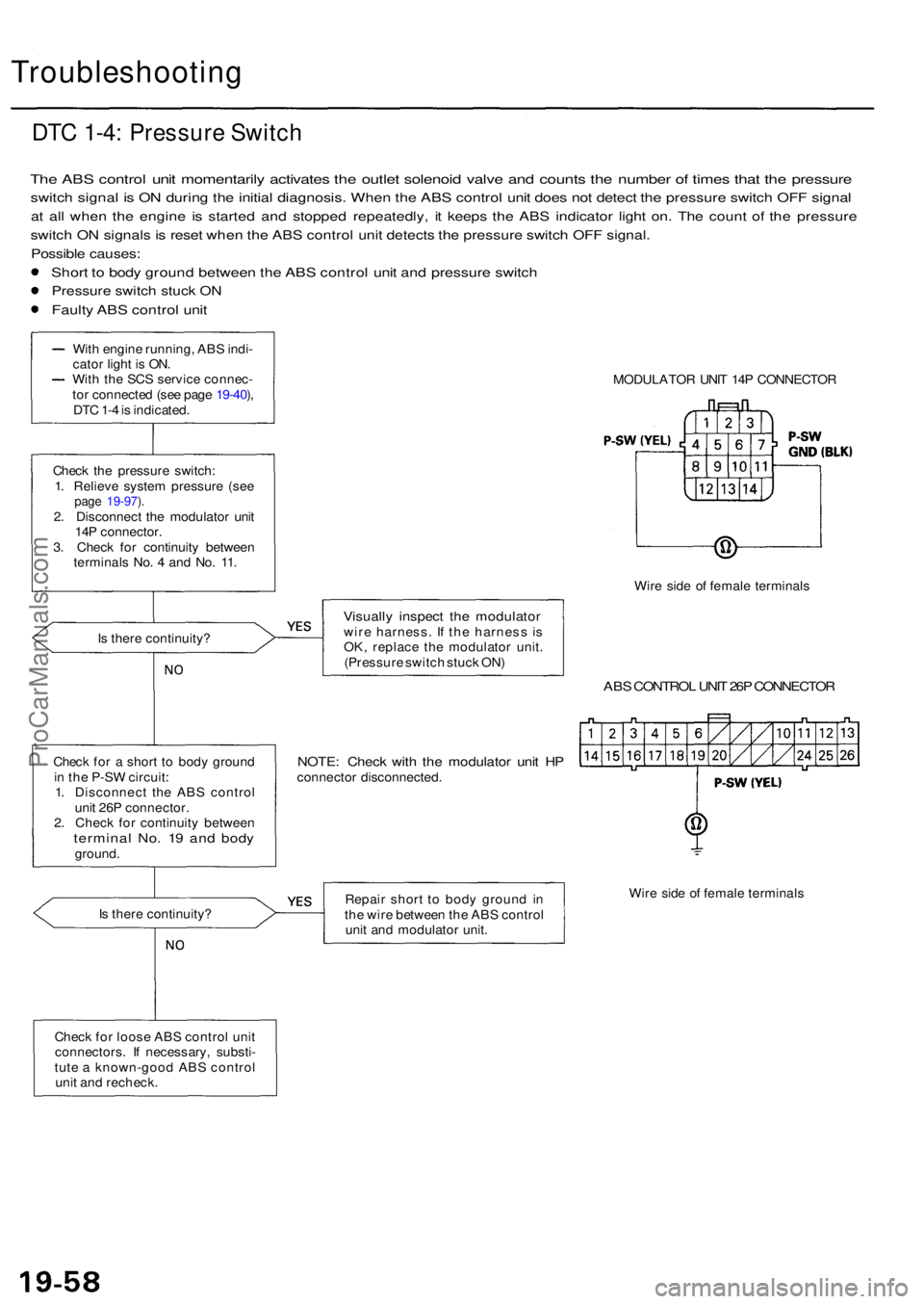
Troubleshooting
DTC 1-4 : Pressur e Switc h
The AB S contro l uni t momentaril y activate s th e outle t solenoi d valv e an d count s th e numbe r o f time s tha t th e pressur e
switch signa l i s O N durin g th e initia l diagnosis . Whe n th e AB S contro l uni t doe s no t detec t th e pressur e switc h OF F signa l
at al l whe n th e engin e i s starte d an d stoppe d repeatedly , i t keep s th e AB S indicato r ligh t on . Th e coun t o f th e pressur e
switch O N signal s i s rese t whe n th e AB S contro l uni t detect s th e pressur e switc h OF F signal .
Possibl e causes :
Short t o bod y groun d betwee n th e AB S contro l uni t an d pressur e switc h
Pressur e switc h stuc k O N
Fault y AB S contro l uni t
MODULATO R UNI T 14 P CONNECTO R
Wir e sid e o f femal e terminal s
Visually inspec t th e modulato rwire harness . I f th e harnes s i s
OK , replac e th e modulato r unit .
(Pressur e switc h stuc k ON )
ABS CONTRO L UNI T 26 P CONNECTO R
NOTE: Chec k wit h th e modulato r uni t H Pconnecto r disconnected .
Repai r shor t t o bod y groun d i n
th e wir e betwee n th e AB S contro l
uni t an d modulato r unit . Wir
e sid e o f femal e terminal s
Chec k fo r loos e AB S contro l uni t
connectors . I f necessary , substi -
tut e a known-goo d AB S contro l
uni t an d recheck .
I
s ther e continuity ?
Chec
k fo r a shor t t o bod y groun d
i n th e P-S W circuit :
1 . Disconnec t th e AB S contro l
uni t 26 P connector .
2 . Chec k fo r continuit y betwee n
termina l No . 1 9 an d bod yground .
Chec
k th e pressur e switch :
1 . Reliev e syste m pressur e (se e
page 19-97 ).2 . Disconnec t th e modulato r uni t
14 P connector .
3 . Chec k fo r continuit y betwee n
terminal s No . 4 an d No . 11 .
I s ther e continuity ?
Wit
h engin e running , AB S indi -
cato r ligh t i s ON .
Wit h th e SC S servic e connec -
to r connecte d (se e pag e 19-40 ),
DT C 1- 4 is indicated .
ProCarManuals.com
Page 1144 of 1954
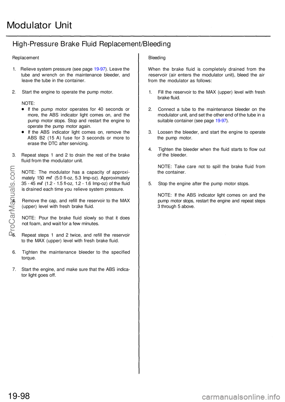
Modulator Uni t
High-Pressur e Brak e Flui d Replacement/Bleedin g
Replacement
1. Reliev e syste m pressur e (se e pag e 19-97 ). Leav e th e
tub e an d wrenc h o n th e maintenanc e bleeder , an d
leav e th e tub e in th e container .
2 . Star t th e engin e t o operat e th e pum p motor .
NOTE:
If th e pum p moto r operate s fo r 4 0 second s o r
more , th e AB S indicato r ligh t come s on , an d th e
pum p moto r stops . Sto p an d restar t th e engin e t o
operat e th e pum p moto r again .
I f th e AB S indicator light come s on , remov e th e
AB S B 2 (1 5 A ) fus e fo r 3 second s o r mor e t o
eras e th e DT C afte r servicing .
3 . Repea t step s 1 an d 2 to drai n th e res t o f th e brak e
fluid fro m th e modulato r unit .
NOTE : Th e modulato r ha s a capacit y o f approxi -
mately 15 0 (5. 0 fl-oz , 5. 3 Imp-oz) . Approximatel y
35 - 4 5 (1. 2 - 1. 5 fl-oz , 1. 2 - 1. 6 Imp-oz ) o f th e flui d
i s draine d eac h tim e yo u reliev e syste m pressure .
4 . Remov e th e cap , an d refil l th e reservoi r t o th e MA X
(upper ) leve l wit h fres h brak e fluid .
NOTE : Pou r th e brak e flui d slowl y s o tha t i t doe s
not foam , an d wai t fo r a fe w minutes .
5. Repea t step s 1 an d 2 twice , an d refil l th e reservoi r
t o th e MA X (upper ) leve l wit h fres h brak e fluid .
6 . Tighte n th e maintenanc e bleede r t o th e specifie d
torque .
7 . Star t th e engine , an d mak e sur e tha t th e AB S indica -
tor ligh t goe s off .
Bleedin g
Whe n th e brak e flui d i s completel y draine d fro m th e
reservoi r (ai r enter s th e modulato r unit) , blee d th e ai r
from th e modulato r a s follows :
1 . Fil l th e reservoi r t o th e MA X (upper ) leve l wit h fres h
brake fluid .
2. Connec t a tub e t o th e maintenanc e bleede r o n th e
modulato r unit , an d se t th e othe r en d o f th e tub e in a
suitabl e containe r (se e pag e 19-97 ).
3 . Loose n th e bleeder , an d star t th e engin e t o operat e
th e pum p motor .
4 . Tighte n th e bleede r whe n th e flui d start s t o flo w ou t
o f th e bleeder .
NOTE : Tak e car e no t t o spil l th e brak e flui d fro m
th e container .
5 . Sto p th e engin e afte r th e pum p moto r stops .
NOTE : I f th e AB S indicato r ligh t come s o n an d th e
pum p moto r stops , restar t th e engin e an d repea t step s
3 throug h 5 above .
19-98ProCarManuals.com
Page 1152 of 1954
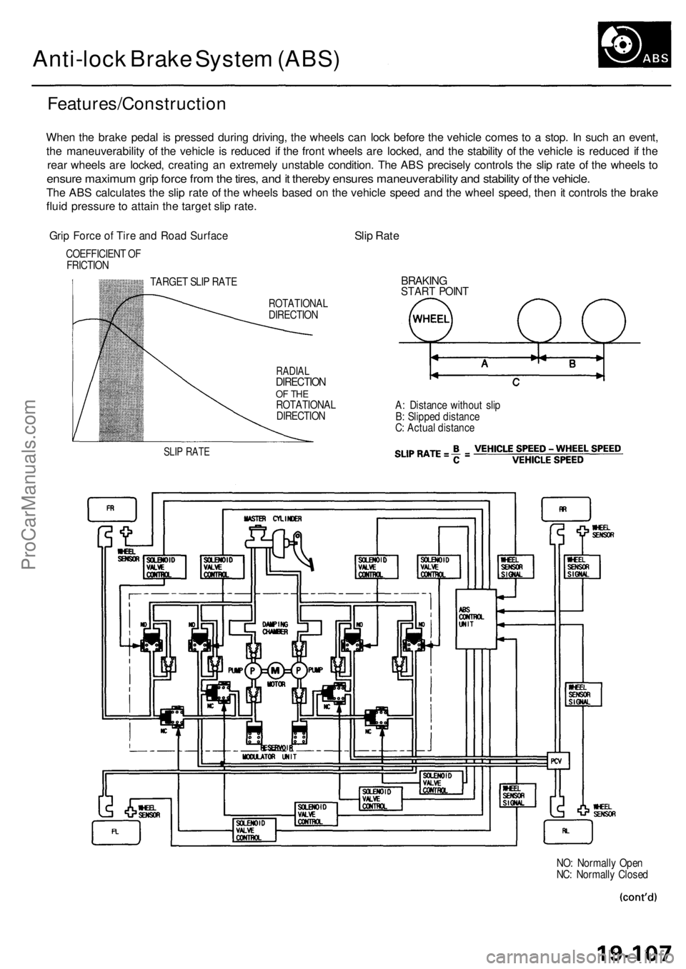
Anti-lock Brak e Syste m (ABS )
Features/Constructio n
When th e brak e peda l i s presse d durin g driving , th e wheel s ca n loc k befor e th e vehicl e come s t o a stop . I n suc h a n event ,
th e maneuverabilit y o f th e vehicl e i s reduce d i f th e fron t wheel s ar e locked , an d th e stabilit y o f th e vehicl e is reduce d if th e
rea r wheel s ar e locked , creatin g a n extremel y unstabl e condition . Th e AB S precisel y control s th e sli p rat e o f th e wheel s t o
ensur e maximu m gri p forc e fro m th e tires , an d it thereb y ensure s maneuverability and stabilit y o f th e vehicle .
The AB S calculate s th e sli p rat e o f th e wheel s base d o n th e vehicl e spee d an d th e whee l speed , the n it control s th e brak e
flui d pressur e to attai n th e targe t sli p rate .
Grip Forc e o f Tir e an d Roa d Surfac eSlip Rat e
COEFFICIEN T O F
FRICTIO N
TARGET SLI P RAT E
SLIP RAT E
ROTATIONA LDIRECTION
RADIALDIRECTIO NOF TH EROTATIONA L
DIRECTIO N
BRAKINGSTART POIN T
A: Distanc e withou t sli p
B : Slippe d distanc e
C : Actua l distanc e
NO: Normall y Ope n
NC : Normall y Close d
ProCarManuals.com
Page 1154 of 1954
Self-diagnosis
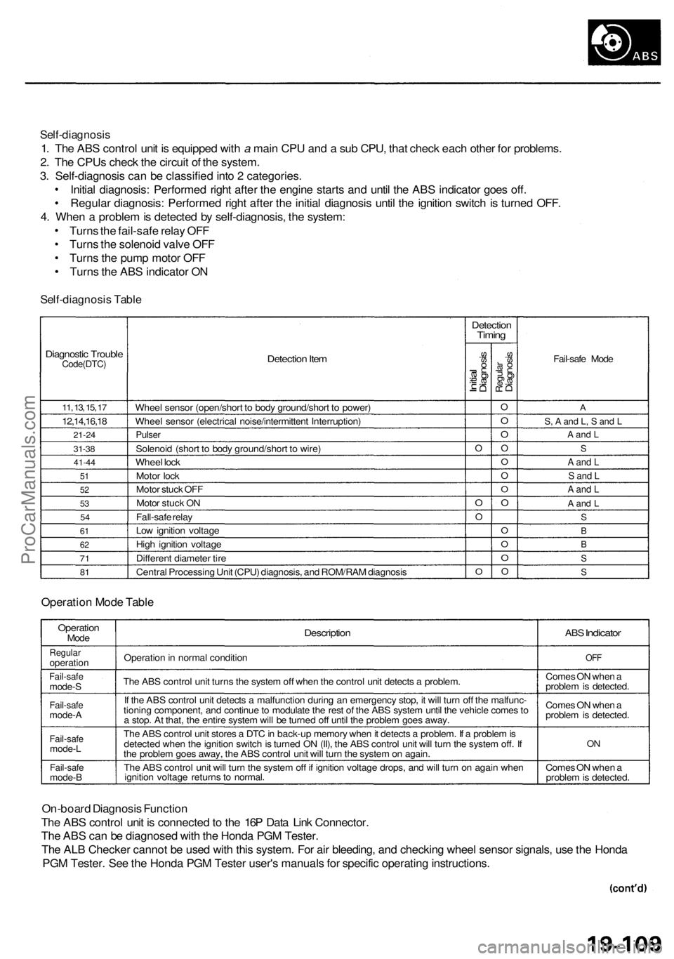
1. The ABS control unit is equipped with a main CPU and a sub CPU, that check each other for problems.
2. The CPUs check the circuit of the system.
3. Self-diagnosis can be classified into 2 categories.
Initial diagnosis: Performed right after the engine starts and until the ABS indicator goes off.
Regular diagnosis: Performed right after the initial diagnosis until the ignition switch is turned OFF.
4. When a problem is detected by self-diagnosis, the system:
Turns the fail-safe relay OFF
Turns the solenoid valve OFF
Turns the pump motor OFF
Turns the ABS indicator ON
Self-diagnosis Table
Diagnostic Trouble
Code(DTC)
11, 13, 15, 17
12,14,16,18
21-24
31-38
41-44
51
52
53
54
61
62
71
81
Detection Item
Wheel sensor (open/short to body ground/short to power)
Wheel sensor (electrical noise/intermittent Interruption)
Pulser
Solenoid (short to body ground/short to wire)
Wheel lock
Motor lock
Motor stuck OFF
Motor stuck ON
Fall-safe relay
Low ignition voltage
High ignition voltage
Different diameter tire
Central Processing Unit (CPU) diagnosis, and ROM/RAM diagnosis
Detection
Timing
Initial
Diagnosis
O
O
O
O
Regular
Diagnosis
O
O
O
O
O
O
O
O
O
O
O
O
Fail-safe Mode
A
S, A and L, S and L
A and L
S
A and L
S and L
A and L
A and L
S
B
B
S
S
Operation Mode Table
Operation
Mode
Regular
operation
Fail-safe
mode-S
Fail-safe
mode-A
Fail-safe
mode-L
Fail-safe
mode-B
Description
Operation in normal condition
The ABS control unit turns the system off when the control unit detects a problem.
If the ABS control unit detects a malfunction during an emergency stop, it will turn off the malfunc-
tioning component, and continue to modulate the rest of the ABS system until the vehicle comes to
a stop. At that, the entire system will be turned off until the problem goes away.
The ABS control unit stores a DTC in back-up memory when it detects a problem. If a problem is
detected when the ignition switch is turned ON (II), the ABS control unit will turn the system off. If
the problem goes away, the ABS control unit will turn the system on again.
The ABS control unit will turn the system off if ignition voltage drops, and will turn on again when
ignition voltage returns to normal.
ABS
Indicator
OFF
Comes ON when a
problem is detected.
Comes ON when a
problem is detected.
ON
Comes ON when a
problem is detected.
On-board Diagnosis Function
The ABS control unit is connected to the 16P Data Link Connector.
The ABS can be diagnosed with the Honda PGM Tester.
The ALB Checker cannot be used with this system. For air bleeding, and checking wheel sensor signals, use the Honda
PGM Tester. See the Honda PGM Tester user's manuals for specific operating instructions.
ProCarManuals.com
Page 1155 of 1954
Anti-lock Brak e Syste m (ABS )
Features/Constructio n (cont'd )
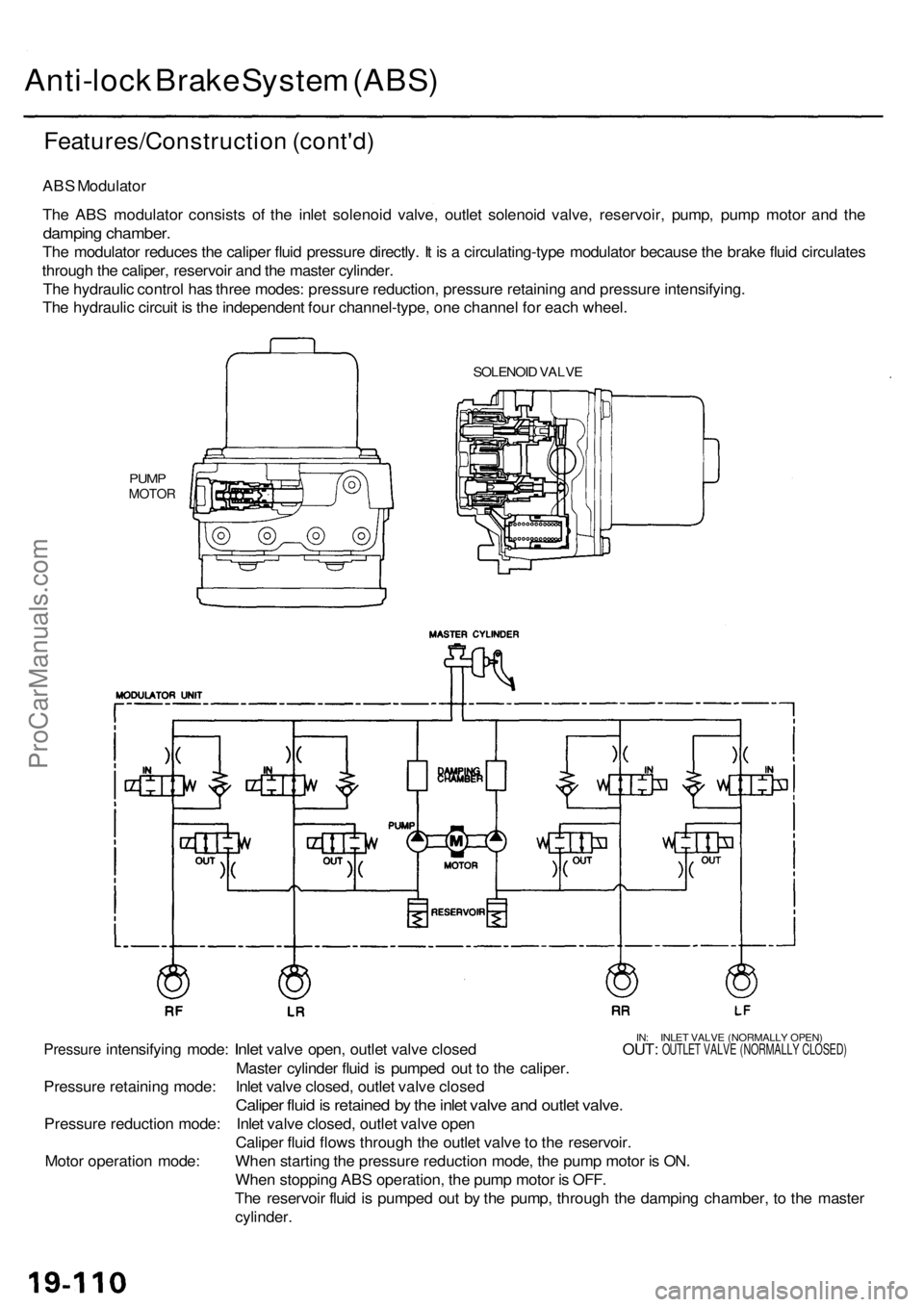
ABS Modulato r
Th e AB S modulato r consist s of the inle t solenoi d valve , outle t solenoi d valve , reservoir , pump , pum p moto r an d th e
dampin g chamber .
The modulato r reduce s th e calipe r flui d pressur e directly . I t i s a circulating-typ e modulato r becaus e th e brak e flui d circulate s
throug h th e caliper , reservoi r an d th e maste r cylinder .
Th e hydrauli c contro l ha s thre e modes : pressur e reduction , pressur e retainin g an d pressur e intensifying .
Th e hydrauli c circui t i s th e independen t fou r channel-type , on e channe l fo r eac h wheel .
SOLENOI D VALV E
PUMPMOTO R
IN: INLE T VALV E (NORMALL Y OPEN )Pressur e intensifyin g mode : Inlet valv e open , outle t valv e close d OUT : OUTLET VALV E (NORMALL Y CLOSED )
Master cylinde r flui d is pumpe d ou t t o th e caliper .
Pressur e retainin g mode : Inle t valv e closed , outle t valv e close d
Caliper flui d is retaine d b y th e inle t valv e an d outle t valve .
Pressur e reductio n mode : Inle t valv e closed , outle t valv e ope n
Calipe r flui d flow s throug h th e outle t valv e to th e reservoir .
Whe n startin g th e pressur e reductio n mode , th e pum p moto r i s ON .
Whe n stoppin g AB S operation , th e pum p moto r i s OFF .
Th e reservoi r flui d is pumpe d ou t b y th e pump , throug h th e dampin g chamber , t o th e maste r
cylinder .
Moto
r operatio n mode :
ProCarManuals.com