Page 1000 of 1954
Power Steering Gearbox
Removal (cont'd)
12. Disconnect the three lines (sensor inlet line, 10 mm
return line and 6 mm return line) from the hoses.
CAUTION: After disconnecting the line, plug or
seal the line with a piece of tape or equivalent.
13. Remove the mounting brackets and steering gear-
box.
NOTE: Before removing the steering gearbox, place
a jack stand under the gearbox to support it.
CAUTION: Be careful not to bend or damage fluid
lines when removing the steering gearbox.ProCarManuals.com
Page 1001 of 1954
Disassembly
Steering Rac k Disassembl y
NOTE:
• Befor e disassemblin g th e gearbox , was h i t of f wit h
solven t an d a brush .
• D o no t di p seal s an d 0-ring s i n solvent .
1 . Remov e th e steerin g gearbo x (se e pag e 17-30 ).
2 . Remov e th e bot h tie-ro d ends .
3 . Remov e th e thre e line s (senso r inle t line , 1 0 m m
retur n lin e an d 6 m m retur n line ) fro m th e valv e bod y
unit.
4. Remov e th e lin e mountin g cushions .
Power Steerin g Gearbo x
ProCarManuals.com
Page 1002 of 1954
5. Remove the boot bands and tie-rod clips. Pull the
boots away from the ends of the gearbox.
6. Hold the steering rack with one wrench ('99 - 01
models: left end only), and unscrew the rack end with
another wrench.
NOTE: '96 - 98 models shown.
CAUTION: Be careful not to damage the rack sur-
face with the wrench.
7. Loosen the locknut, then remove the rack guide
screw and O-ring ('96 - 98 models only).
8. Remove the spring and rack guide from the gearbox
housing.
9. Remove cylinder lines A and B from the gearbox.
10. Drain the fluid from the cylinder fittings by slowly
moving the steering rack back and forth.ProCarManuals.com
Page 1008 of 1954
37. Check the two control valves.
NOTE: If the valves are damaged, replace the steer-
ing gearbox as an assembly.
Assist Control Valve:
• Inspect its surface for scoring and scratches.
• Slip it back into the valve body unit, and make
sure it slides smoothly without drag or side play.
38. Separate the valve body and valve housing.
39. Remove the housing seal and dowel pins from the
valve body unit.
Pressure Control Valve:
• Inspect its surface for scoring and scratches.
• Slip it back into the valve body unit, and make
sure it slides smoothly without drag or side play.
36. Remove the pressure control valve, assist control
valve and springs from the valve body.ProCarManuals.com
Page 1020 of 1954
5. Reconnect the feed line to upper side of the valve
body unit.
2. Position the line mounting cushions by aligning the
marks on the 10 mm return line (large diameter
line).
3. Install the feed line on the slot of the cushions.
4. Install the two line clamps on the line mounting
cushions as shown below.
Installation
CAUTION: Be careful not to bend or damage cylinder
lines A and B or the four fluid lines when installing the
gearbox.
1. Assemble the mounting bracket over the mount
cushion, then loosely install the gearbox on the rear
beam with two gearbox mounting bolts.
NOTE: Move the feed line over the gearbox so that
it does not interfere with the gearbox during instal-
lation.ProCarManuals.com
Page 1380 of 1954

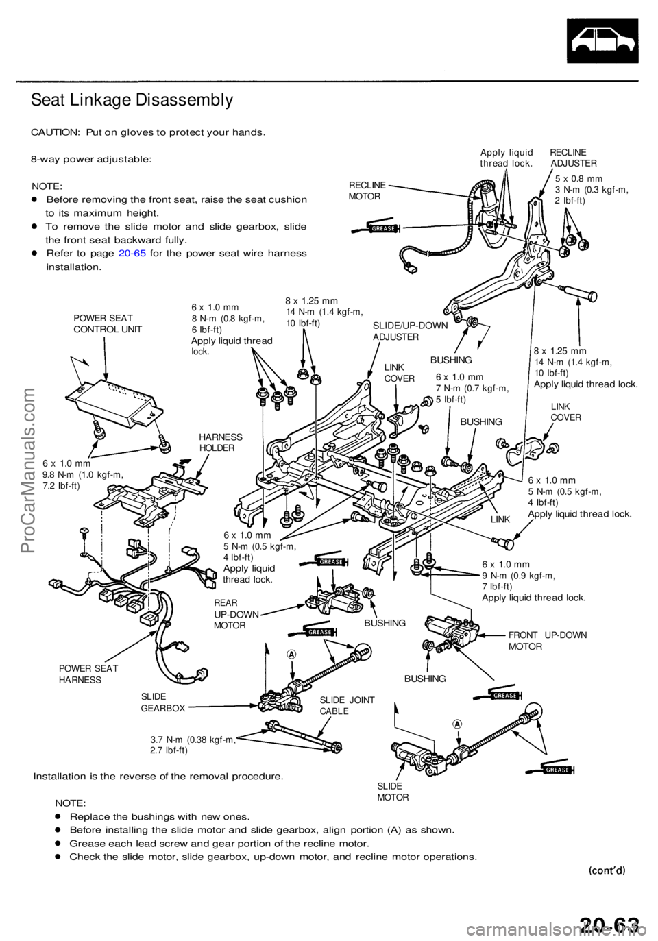
Seat Linkag e Disassembl y
CAUTION: Pu t o n glove s to protec t you r hands .
8-wa y powe r adjustable :
NOTE:
Before removin g th e fron t seat , rais e th e sea t cushio n
t o it s maximu m height .
T o remov e th e slid e moto r an d slid e gearbox , slid e
th e fron t sea t backwar d fully .
Refe r t o pag e 20-6 5 fo r th e powe r sea t wir e harnes s
installation .
POWER SEA TCONTRO L UNI T
Appl y liqui d RECLIN E
threa d lock . ADJUSTE R
RECLIN E
MOTO R
5 x 0. 8 m m3 N- m (0. 3 kgf-m ,
2 Ibf-ft )
8 x 1.2 5 mm14 N- m (1. 4 kgf-m ,
1 0 Ibf-ft )
Apply liqui d threa d lock .
6 x 1. 0 m m9.8 N- m (1. 0 kgf-m ,
7. 2 Ibf-ft )6 x 1. 0 m m5 N- m (0. 5 kgf-m ,
4 Ibf-ft )
Apply liqui d threa d lock .
POWE R SEA T
HARNES S
SLIDE
GEARBO X
3.7 N- m (0.3 8 kgf-m ,
2. 7 Ibf-ft )
Installatio n is th e revers e o f th e remova l procedure .SLIDE
MOTO R
NOTE:
Replac e th e bushing s wit h ne w ones .
Befor e installin g th e slid e moto r an d slid e gearbox , alig n portio n (A) a s shown .
Greas e eac h lea d scre w an d gea r portio n o f th e reclin e motor .
Chec k th e slid e motor , slid e gearbox , up-dow n motor , an d reclin e moto r operations .
SLIDE JOIN TCABLE
BUSHIN G
FRONT UP-DOW NMOTOR
6 x 1. 0 m m9 N- m (0. 9 kgf-m ,
7 Ibf-ft )
Apply liqui d threa d lock .
BUSHIN G
LINK LIN
K
COVE RBUSHIN G
6 x 1. 0 m m7 N- m (0. 7 kgf-m ,
5 Ibf-ft )
BUSHIN GLINKCOVE R
SLIDE/UP-DOW NADJUSTER
6 x 1. 0 m m8 N- m (0. 8 kgf-m ,
6 Ibf-ft )
Apply liqui d threa dlock.
8 x 1.2 5 m m14 N- m (1. 4 kgf-m ,
1 0 Ibf-ft )
HARNES SHOLDER
6 x 1. 0 m m5 N- m (0. 5 kgf-m ,
4 Ibf-ft )
Apply liqui dthrea d lock .
REARUP-DOW NMOTOR
ProCarManuals.com
Page 1381 of 1954

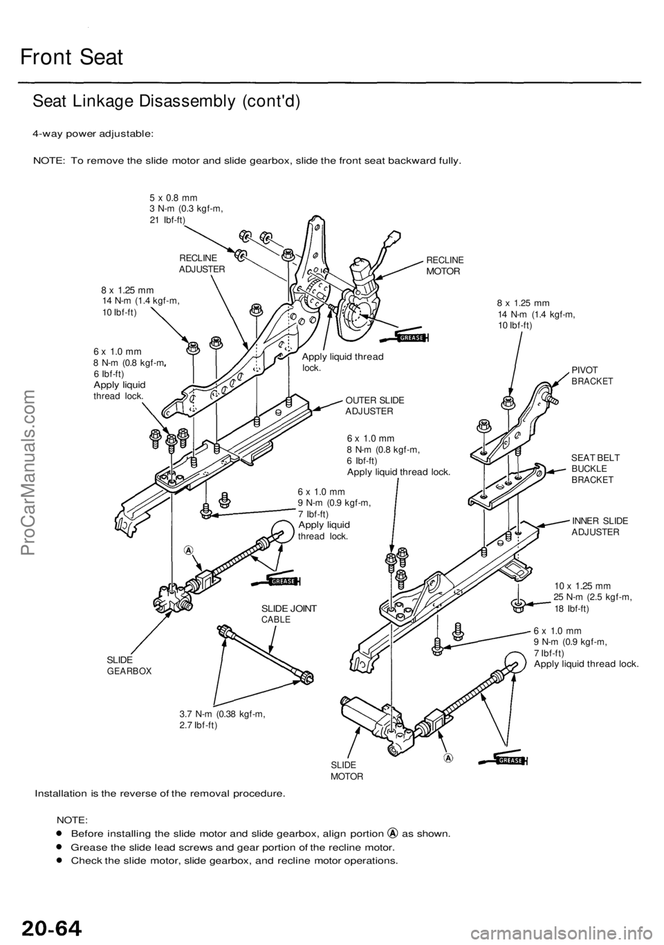
Front Sea t
Seat Linkag e Disassembl y (cont'd )
4-way powe r adjustable :
NOTE : T o remov e th e slid e moto r an d slid e gearbox , slid e th e fron t sea t backwar d fully .
5 x 0. 8 m m3 N- m (0. 3 kgf-m ,
2 1 Ibf-ft )
RECLIN EMOTOR
8 x 1.2 5 mm14 N- m (1. 4 kgf-m ,
1 0 Ibf-ft )
6 x 1. 0 m m8 N- m (0. 8 kgf- m
6 Ibf-ft )
Apply liqui dthrea d lock .
8 x 1.2 5 mm14 N- m (1. 4 kgf-m ,
1 0 Ibf-ft )
PIVOT
BRACKE T
SEAT BEL TBUCKL EBRACKE T
INNER SLID E
ADJUSTE R
10 x 1.2 5 mm25 N- m (2. 5 kgf-m ,
1 8 Ibf-ft )
SLIDEGEARBO X
6 x 1. 0 m m9 N- m (0. 9 kgf-m ,
7 Ibf-ft )
Apply liqui d threa d lock .
3.7 N- m (0.3 8 kgf-m ,
2. 7 Ibf-ft )
Installatio n is th e revers e o f th e remova l procedure .
SLIDEMOTO R
NOTE:
Before installin g th e slid e moto r an d slid e gearbox , alig n portio n a s shown .
Greas e th e slid e lea d screw s an d gea r portio n o f th e reclin e motor .
Chec k th e slid e motor , slid e gearbox , an d reclin e moto r operations .
6 x 1. 0 m m8 N- m (0. 8 kgf-m ,
6 Ibf-ft )
Apply liqui d threa d lock .
OUTE R SLID E
ADJUSTE R
RECLIN
E
ADJUSTE R
Apply liqui d threa dlock.
6 x 1. 0 m m9 N- m (0. 9 kgf-m ,
7 Ibf-ft )
Apply liqui dthrea d lock .
SLIDE JOIN TCABL E
ProCarManuals.com