Page 751 of 2543
INSPECTION PROCEDURE
(See page IN±30).
(1) Remove engine hood lock assembly.
(2) Disconnect engine hood courtesy switch con-
nector.
Check continuity between terminals 1 and 2 when
engine hood lock is locked and unlocked.
Check and replace theft deterrent and door lock
ECU (See page
IN±30).
Check engine hood courtesy switch.
Engine hood lock
Lock
Unlock
Terminal
Continuity
12
Repair or replace harness or connector.
Replace engine hood courtesy switch.
Check harness and connector between theft deterrent and door lock ECU
and switch and body ground (See page IN±30).
± BODY ELECTRICAL SYSTEMBE±149THEFT DETERRENT AND DOOR LOCK CONTROL SYSTEM
Page 752 of 2543
CIRCUIT INSPECTION
ECU Power Source±Circuit
CIRCUIT DESCRIPTION
This circuit provides power to operate the theft deterrent and door lock ECU.
BE±150± BODY ELECTRICAL SYSTEM
THEFT DETERRENT AND DOOR LOCK CONTROL SYSTEM
Page 753 of 2543
(See page Be±123).
(See page IN±30).
Remove DOME fuse from R/B No. 2
Repair or replace harness or connector.
Check continuity of DOME fuse.
Continuity
Check for short in all the harness and components
connected to the DOME fuse (See attached wiring
diagram).
Proceed to next circuit inspection shown on matrix
chart (See page BE±123).
(1)Remove the No. 1 under cover and heater duct.
(2)Disconnect the theft deterrent and door lock ECU
connector.
Measure voltage between terminals +B1 and E of
ECU connector.
Check DOME fuse.
Check voltage between terminals +B1 and E of ECU connector.
Check for open in harness and connector between ECU and body ground
(See page IN±30).
Voltage: 10 ± 14 V
Check and repair harness and connector be-
tween ECU and battery.
INSPECTION PROCEDURES
± BODY ELECTRICAL SYSTEMBE±151THEFT DETERRENT AND DOOR LOCK CONTROL SYSTEM
Page 754 of 2543
Actuator Power Source Circuit
CIRCUIT DESCRIPTION
This circuit provides power to drive the door lock motor.
BE±152± BODY ELECTRICAL SYSTEM
THEFT DETERRENT AND DOOR LOCK CONTROL SYSTEM
Page 755 of 2543

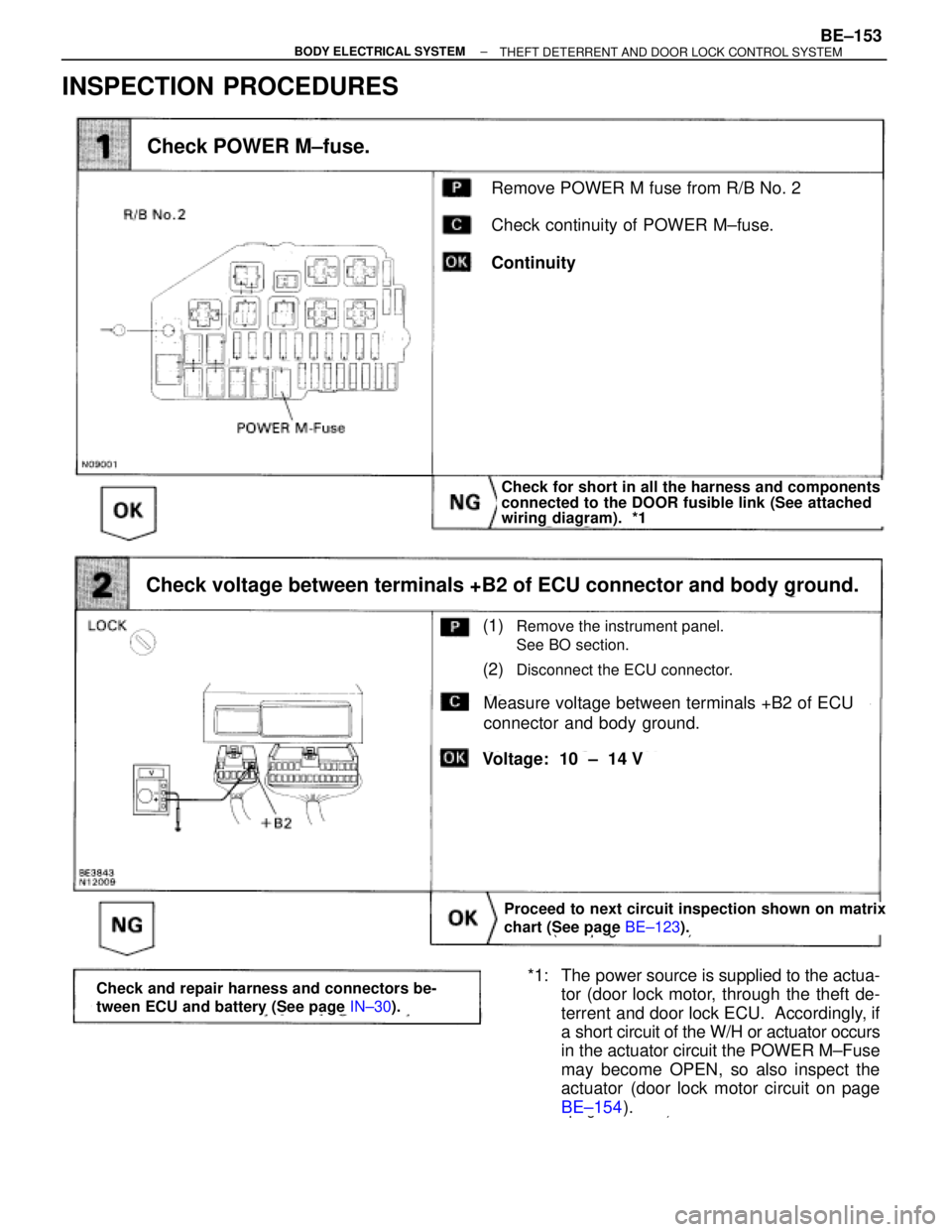
INSPECTION PROCEDURES
(See page BE±123).
page BE±154).
Remove POWER M fuse from R/B No. 2
Check continuity of POWER M±fuse.
Continuity
Check POWER M±fuse.
Check for short in all the harness and components
connected to the DOOR fusible link (See attached
wiring diagram). *1
Proceed to next circuit inspection shown on matrix
chart (See page BE±123).
(1)Remove the instrument panel.
See BO section.
(2)Disconnect the ECU connector.
Measure voltage between terminals +B2 of ECU
connector and body ground.
Check voltage between terminals +B2 of ECU connector and body ground.
Voltage: 10 ± 14 V
*1: The power source is supplied to the actua-
tor (door lock motor, through the theft de-
terrent and door lock ECU. Accordingly, if
a short circuit of the W/H or actuator occurs
in the actuator circuit the POWER M±Fuse
may become OPEN, so also inspect the
actuator (door lock motor circuit on page
BE±154).Check and repair harness and connectors be-
tween ECU and battery (See page IN±30).
± BODY ELECTRICAL SYSTEMBE±153THEFT DETERRENT AND DOOR LOCK CONTROL SYSTEM
Page 756 of 2543
Check operating sound of door lock motor, when
door lock control switch is pushed to the lock side
and unlock side.
Inspect the door which is malfunctioning.
Can hear operating sound of door lock motor.
Check operating sound of door lock motor.
Repair or replace door lock control link.
Door Lock Motor Circuit
CIRCUIT DESCRIPTION
This door lock motor locks and unlocks the door according to signals from the ECU.
INSPECTION PROCEDURES
BE±154± BODY ELECTRICAL SYSTEMTHEFT DETERRENT AND DOOR LOCK CONTROL SYSTEM
Page 757 of 2543
(See page BE±123).
(See page IN±30).
(1)Remove the door trim and service hole cover..
(2)Disconnect the door lock motor connector.
This inspection must be carried out within 2 seconds.
Replace door lock motor.
Check door lock motor.
(1)Connect positive (+) lead to terminal 2(4) and
negative (±) lead to terminal 2(4) of door lock
motor connector.
(2)Connect positive (+) lead to terminal 4(2) and
negative (±) lead to terminal 2(4) of door lock
motor connector.
( ) Passenger's Side
(1)Door lock motor locks door.
(2)Door lock motor unlocks door.
Repair or replace harness or connector.
Check harness and connectors between ECU and door lock motor
(See page
IN±30).
Proceed to next circuit inspection shown on
matrix chart (See page
BE±123).
Go to step
± BODY ELECTRICAL SYSTEMBE±155THEFT DETERRENT AND DOOR LOCK CONTROL SYSTEM
Page 758 of 2543
Door Lock Control Switch Circuit
CIRCUIT DESCRIPTION
When the door lock control switch is pushed to the lock side, Lock terminal of the switch is grounded, and when
the switch is pushed to the unlock side, Unlock terminal is grounded (See wiring diagram below).
BE±156± BODY ELECTRICAL SYSTEMTHEFT DETERRENT AND DOOR LOCK CONTROL SYSTEM