Page 1509 of 2543
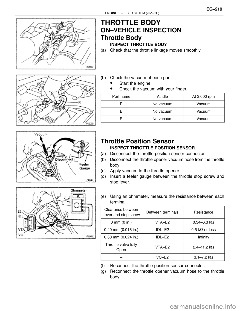
THROTTLE BODY
ON±VEHICLE INSPECTION
Throttle Body
INSPECT THROTTLE BODY
(a) Check that the throttle linkage moves smoothly.
(b) Check the vacuum at each port.
wStart the engine.
wCheck the vacuum with your finger.
�������� ��������Port name�������� ��������At idle�������� ��������At 3,000 rpm
�������� ��������P�������� ��������No vacuum�������� ��������Vacuum�������� �
������� ��������E
�������� �
������� ��������No vacuum
�������� �
������� ��������Vacuum
�������� ��������R�������� ��������No vacuum�������� ��������Vacuum
Throttle Position Sensor
INSPECT THROTTLE POSITION SENSOR
(a) Disconnect the throttle position sensor connector.
(b) Disconnect the throttle opener vacuum hose from the throttle
body.
(c) Apply vacuum to the throttle opener.
(d) Insert a feeler gauge between the throttle stop screw and
stop lever.
(e) Using an ohmmeter, measure the resistance between each
terminal.
�������� �
������� ��������
Clearance between
Lever and stop screw�������� �
������� ��������Between terminals�������� �
������� ��������Resistance
�������� ��������0 mm (0 in.)�������� ��������VTA±E2�������� ��������0.34±6.3 k�
�������� ��������0.40 mm (0.016 in.)�������� ��������IDL±E2�������� ��������0.5 k� or less
�������� ��������0.60 mm (0.024 in.)�������� ��������IDL±E2�������� ��������Infinity�������� �
������� �
������� ��������
Throttle valve fully
Open
�������� �
������� �
������� ��������
VTA±E2
�������� �
������� �
������� ��������
2.4±11.2 k�
�������� ��������±�������� ��������VC±E2�������� ��������3.1±7.2 k�
(f) Reconnect the throttle position sensor connector.
(g) Reconnect the throttle opener vacuum hose to the throttle
body.
± ENGINESFI SYSTEM (2JZ±GE)EG±219
Page 1552 of 2543
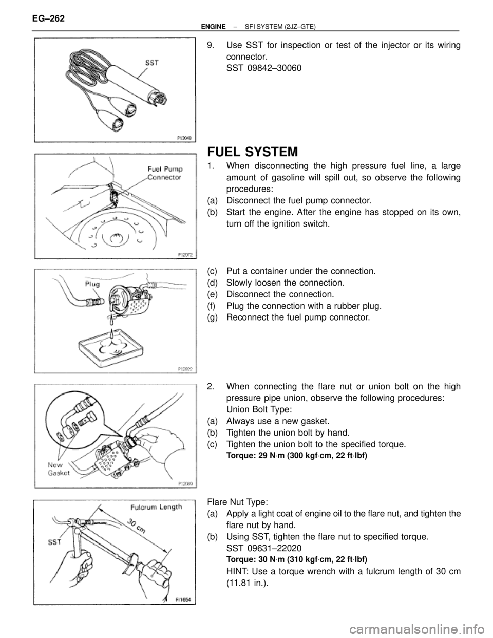
9. Use SST for inspection or test of the injector or its wiring
connector.
SST 09842±30060
FUEL SYSTEM
1. When disconnecting the high pressure fuel line, a large
amount of gasoline will spill out, so observe the following
procedures:
(a) Disconnect the fuel pump connector.
(b) Start the engine. After the engine has stopped on its own,
turn off the ignition switch.
(c) Put a container under the connection.
(d) Slowly loosen the connection.
(e) Disconnect the connection.
(f) Plug the connection with a rubber plug.
(g) Reconnect the fuel pump connector.
2. When connecting the flare nut or union bolt on the high
pressure pipe union, observe the following procedures:
Union Bolt Type:
(a) Always use a new gasket.
(b) Tighten the union bolt by hand.
(c) Tighten the union bolt to the specified torque.
Torque: 29 NVm (300 kgfVcm, 22 ftVlbf)
Flare Nut Type:
(a) Apply a light coat of engine oil to the flare nut, and tighten the
flare nut by hand.
(b) Using SST, tighten the flare nut to specified torque.
SST 09631±22020
Torque: 30 NVm (310 kgfVcm, 22 ftVlbf)
HINT: Use a torque wrench with a fulcrum length of 30 cm
(11.81 in.). EG±262
± ENGINESFI SYSTEM (2JZ±GTE)
Page 1555 of 2543
(g) Reconnect the negative (±) terminal cable to the battery.
(h) Turn the ignition switch ON.
(i) Measure the fuel pressure.
Fuel pressure:
226±275 kPa (2.3±2.8 kgf/cm
2, 33±40 psi)
If pressure is high, replace the fuel pressure regulator.
If pressure is low, check the following parts:
wFuel hoses and connections
wFuel pump
wFuel filter
wFuel pressure regulator
(j) Remove the SST from the DLC1.
SST 09843±18020
(k) Start the engine.
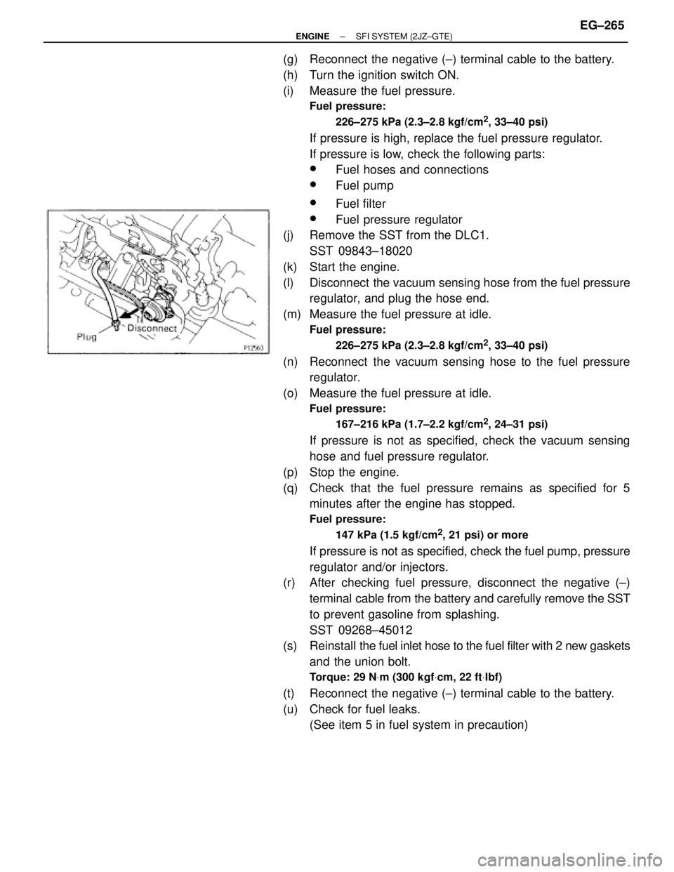
(l) Disconnect the vacuum sensing hose from the fuel pressure
regulator, and plug the hose end.
(m) Measure the fuel pressure at idle.
Fuel pressure:
226±275 kPa (2.3±2.8 kgf/cm
2, 33±40 psi)
(n) Reconnect the vacuum sensing hose to the fuel pressure
regulator.
(o) Measure the fuel pressure at idle.
Fuel pressure:
167±216 kPa (1.7±2.2 kgf/cm
2, 24±31 psi)
If pressure is not as specified, check the vacuum sensing
hose and fuel pressure regulator.
(p) Stop the engine.
(q) Check that the fuel pressure remains as specified for 5
minutes after the engine has stopped.
Fuel pressure:
147 kPa (1.5 kgf/cm
2, 21 psi) or more
If pressure is not as specified, check the fuel pump, pressure
regulator and/or injectors.
(r) After checking fuel pressure, disconnect the negative (±)
terminal cable from the battery and carefully remove the SST
to prevent gasoline from splashing.
SST 09268±45012
(s) Reinstall the fuel inlet hose to the fuel filter with 2 new gaskets
and the union bolt.
Torque: 29 NVm (300 kgfVcm, 22 ftVlbf)
(t) Reconnect the negative (±) terminal cable to the battery.
(u) Check for fuel leaks.
(See item 5 in fuel system in precaution)
± ENGINESFI SYSTEM (2JZ±GTE)EG±265
Page 1638 of 2543
ON±VEHICLE INSPECTION
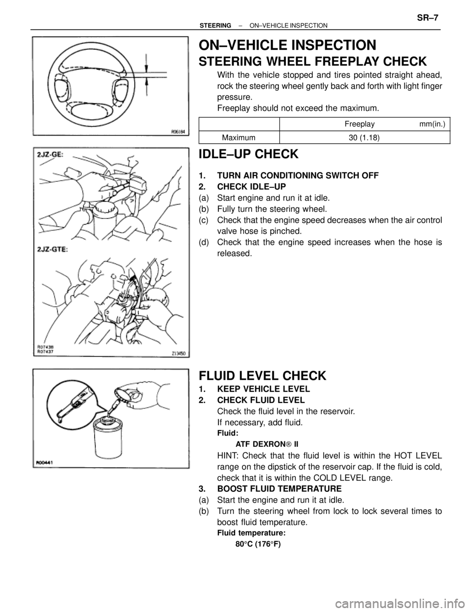
STEERING WHEEL FREEPLAY CHECK
With the vehicle stopped and tires pointed straight ahead,
rock the steering wheel gently back and forth with light finger
pressure.
Freeplay should not exceed the maximum.
�������� �
�������
��������������� �
�������������� Freeplay mm(in.)�������� ��������
Maximum30 (1 18)�������� ��������Maximum30 (1.18)
IDLE±UP CHECK
1. TURN AIR CONDITIONING SWITCH OFF
2. CHECK IDLE±UP
(a) Start engine and run it at idle.
(b) Fully turn the steering wheel.
(c) Check that the engine speed decreases when the air control
valve hose is pinched.
(d) Check that the engine speed increases when the hose is
released.
FLUID LEVEL CHECK
1. KEEP VEHICLE LEVEL
2. CHECK FLUID LEVEL
Check the fluid level in the reservoir.
If necessary, add fluid.
Fluid:
ATF DEXRON[ II
HINT: Check that the fluid level is within the HOT LEVEL
range on the dipstick of the reservoir cap. If the fluid is cold,
check that it is within the COLD LEVEL range.
3. BOOST FLUID TEMPERATURE
(a) Start the engine and run it at idle.
(b) Turn the steering wheel from lock to lock several times to
boost fluid temperature.
Fluid temperature:
805C (1765F)
± STEERINGON±VEHICLE INSPECTIONSR±7
Page 1639 of 2543
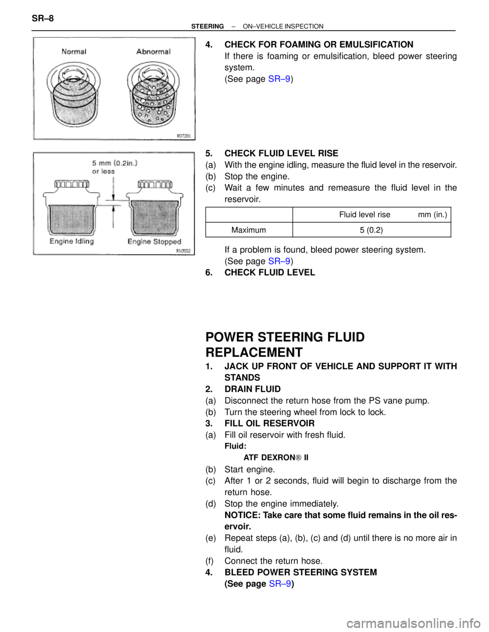
4. CHECK FOR FOAMING OR EMULSIFICATION
If there is foaming or emulsification, bleed power steering
system.
(See page SR±9)
5. CHECK FLUID LEVEL RISE
(a) With the engine idling, measure the fluid level in the reservoir.
(b) Stop the engine.
(c) Wait a few minutes and remeasure the fluid level in the
reservoir.
�������� �
������� ��������
�������������� �
������������� �������������� Fluid level rise mm (in.)
��������Maximum5(02)�������� ��������Maximum5 (0.2)
If a problem is found, bleed power steering system.
(See page SR±9)
6. CHECK FLUID LEVEL
POWER STEERING FLUID
REPLACEMENT
1. JACK UP FRONT OF VEHICLE AND SUPPORT IT WITH
STANDS
2. DRAIN FLUID
(a) Disconnect the return hose from the PS vane pump.
(b) Turn the steering wheel from lock to lock.
3. FILL OIL RESERVOIR
(a) Fill oil reservoir with fresh fluid.
Fluid:
ATF DEXRON[ II
(b) Start engine.
(c) After 1 or 2 seconds, fluid will begin to discharge from the
return hose.
(d) Stop the engine immediately.
NOTICE: Take care that some fluid remains in the oil res-
ervoir.
(e) Repeat steps (a), (b), (c) and (d) until there is no more air in
fluid.
(f) Connect the return hose.
4. BLEED POWER STEERING SYSTEM
(See page SR±9) SR±8
± STEERINGON±VEHICLE INSPECTION
Page 1640 of 2543
POWER STEERING SYSTEM BLEEDING
1. JACK UP FRONT OF VEHICLE AND SUPPORT IT WITH
STANDS
2. TURN STEERING WHEEL
With the engine stopped, turn the steering slowly from lock
to lock several times.
NOTICE: Take care that some fluid remains in the oil res-
ervoir.
3. LOWER VEHICLE
4. START ENGINE
Run the engine at idle for a few minutes.
5. TURN STEERING WHEEL
(a) With the engine at idling, turn the wheel to left or right full lock
and keep it there for 2±3 seconds, then turn the wheel to the
opposite full lock and keep it there for 2±3 seconds.
(b) Repeat (a) several times.
6. STOP ENGINE
7. CHECK FOR FOAMING OR EMULSIFICATION
If the system has to be bled twice specifically because of
foaming or emulsification, check for fluid leaks in the system.
8. CHECK FLUID LEVEL
(See page SR±7)
± STEERINGON±VEHICLE INSPECTIONSR±9
Page 1902 of 2543
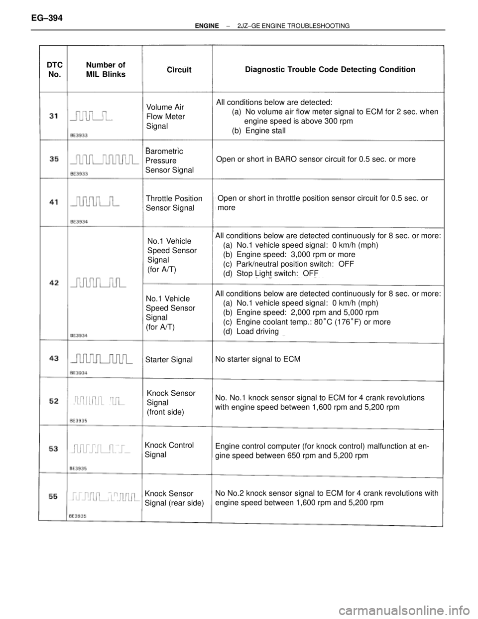
DTC
No.Number of
MIL BlinksCircuitDiagnostic Trouble Code Detecting Condition
Volume Air
Flow Meter
Signal
Barometric
Pressure
Sensor Signal
Throttle Position
Sensor Signal
No.1 Vehicle
Speed Sensor
Signal
(for A/T)
No.1 Vehicle
Speed Sensor
Signal
(for A/T)
Starter Signal
Knock Sensor
Signal
(front side)
Knock Control
Signal
Knock Sensor
Signal (rear side)
All conditions below are detected:
(a) No volume air flow meter signal to ECM for 2 sec. when
engine speed is above 300 rpm
(b) Engine stall
Open or short in BARO sensor circuit for 0.5 sec. or more
Open or short in throttle position sensor circuit for 0.5 sec. or
more
All conditions below are detected continuously for 8 sec. or more:
(a) No.1 vehicle speed signal: 0 km/h (mph)
(b) Engine speed: 3,000 rpm or more
(c) Park/neutral position switch: OFF
(d) Stop Light switch: OFF
All conditions below are detected continuously for 8 sec. or more:
(a) No.1 vehicle speed signal: 0 km/h (mph)
(b) Engine speed: 2,000 rpm and 5,000 rpm
(c) Engine coolant temp.: 80°C (176°F) or more
(d) Load driving
No starter signal to ECM
No. No.1 knock sensor signal to ECM for 4 crank revolutions
with engine speed between 1,600 rpm and 5,200 rpm
Engine control computer (for knock control) malfunction at en-
gine speed between 650 rpm and 5,200 rpm
No No.2 knock sensor signal to ECM for 4 crank revolutions with
engine speed between 1,600 rpm and 5,200 rpm
EG±394± ENGINE2JZ±GE ENGINE TROUBLESHOOTING
Page 1908 of 2543
BASIC INSPECTION
In many cases, by carrying out the basic engine check shown in the following flow chart, the location causing
the problem can be found quickly and efficiently. Therefore, use of this check is essential in engine trouble-
shooting.
If there is a problem, and a normal code is displayed, proceed to the matrix chart of problem symptoms on page
EG±408. Make sure that every likely cause of the problem is checked.
EG±408.
Is battery positive voltage 11 V or more when engine is stopped?
Is engine cranked?
Does engine start?
Check air filter.
Charge or replace battery.
Proceed to matrix chart of problem symptoms
on page EG±408.
Repair or replace.
Remove air filter.
Visually check that the air filter is not excessive dirty or
oily.
If necessary, clean the air filter with compressed air. First
blow from inside thoroughly, then blow from outside of
the air filter.
EG±400± ENGINE2JZ±GE ENGINE TROUBLESHOOTING