Page 1659 of 2543
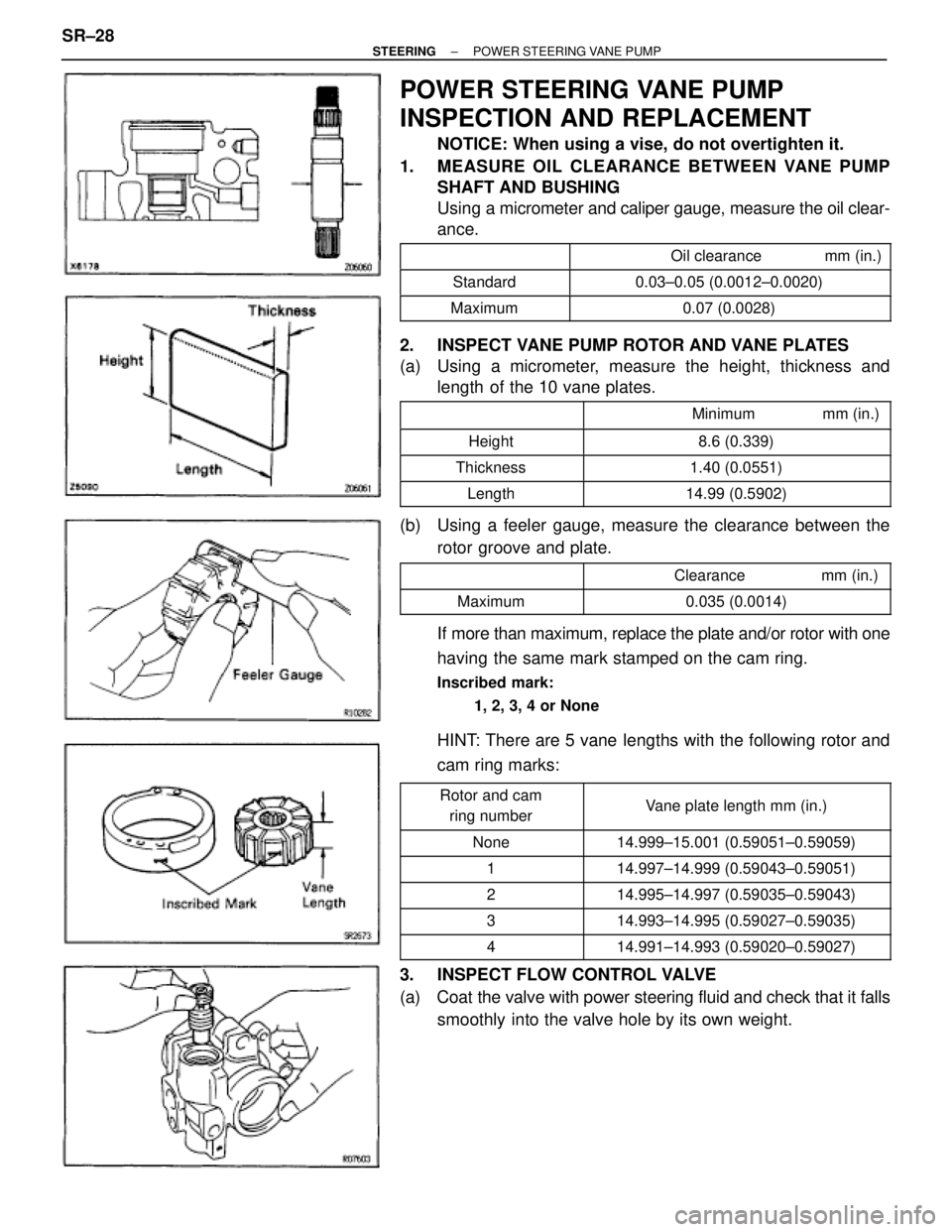
POWER STEERING VANE PUMP
INSPECTION AND REPLACEMENT
NOTICE: When using a vise, do not overtighten it.
1. MEASURE OIL CLEARANCE BETWEEN VANE PUMP
SHAFT AND BUSHING
Using a micrometer and caliper gauge, measure the oil clear-
ance.
�������� ����������������������� ��������������� Oil clearance mm (in.)
�������� ��������Standard��������������� ���������������0.03±0.05 (0.0012±0.0020)
�������� ��������Maximum��������������� ���������������0.07 (0.0028)
2. INSPECT VANE PUMP ROTOR AND VANE PLATES
(a) Using a micrometer, measure the height, thickness and
length of the 10 vane plates.
��������� ����������������������� �������������� Minimum mm (in.)��������� �
�������� ���������Height
�������������� �
������������� ��������������8.6 (0.339)
��������� ���������Thickness�������������� ��������������1.40 (0.0551)
��������� ���������Length�������������� ��������������14.99 (0.5902)
(b) Using a feeler gauge, measure the clearance between the
rotor groove and plate.
��������� ����������������������� �������������� Clearance mm (in.)
��������� ���������Maximum�������������� ��������������0.035 (0.0014)
If more than maximum, replace the plate and/or rotor with one
having the same mark stamped on the cam ring.
Inscribed mark:
1, 2, 3, 4 or None
HINT: There are 5 vane lengths with the following rotor and
cam ring marks:
��������� �
�������� ���������Rotor and cam
ring number�������������� �
������������� ��������������Vane plate length mm (in.)
��������� ���������None�������������� ��������������14.999±15.001 (0.59051±0.59059)��������� ���������1�������������� ��������������14.997±14.999 (0.59043±0.59051)��������� �
��������2
�������������� �
�������������14.995±14.997 (0.59035±0.59043)��������� �
�������� ���������3
�������������� �
������������� ��������������14.993±14.995 (0.59027±0.59035)
��������� ���������4�������������� ��������������14.991±14.993 (0.59020±0.59027)
3. INSPECT FLOW CONTROL VALVE
(a) Coat the valve with power steering fluid and check that it falls
smoothly into the valve hole by its own weight. SR±28
± STEERINGPOWER STEERING VANE PUMP
Page 1660 of 2543
(b) Check the valve for leakage. Close one of the holes and
apply 392±490 kPa (4±5 kgf/cm
2, 57±71 psi) of compressed
air into the opposite side, and confirm that air does not come
out from the end holes.
If necessary, replace the valve with one having the same let-
ter as inscribed on the front housing.
Inscribed mark:
A, B, C, D, E or F
4. INSPECT SPRING
Using calipers, measure the free length of the spring.
������� ����������������������� ���������������� Free length mm (in.)������� �������Minimum���������������� ����������������33 (1.30)
5. IF NECESSARY, REPLACE OIL SEAL
(a) Using SST, tap out the oil seal.
SST 09631±10030
NOTICE: Be careful not to damage the bushing of the
front housing.
(b) Coat a new oil seal lip with power steering fluid.
(c) Using a socket wrench (24 mm), press in the oil seal.
NOTICE: Make sure you install the oil seal facing the cor-
rect direction.
± STEERINGPOWER STEERING VANE PUMPSR±29
Page 1661 of 2543
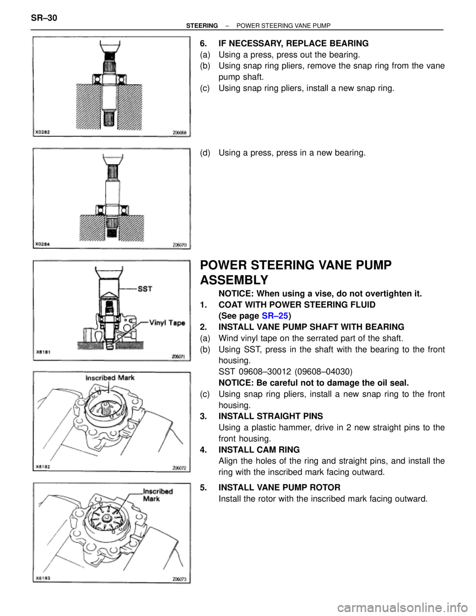
6. IF NECESSARY, REPLACE BEARING
(a) Using a press, press out the bearing.
(b) Using snap ring pliers, remove the snap ring from the vane
pump shaft.
(c) Using snap ring pliers, install a new snap ring.
(d) Using a press, press in a new bearing.
POWER STEERING VANE PUMP
ASSEMBLY
NOTICE: When using a vise, do not overtighten it.
1. COAT WITH POWER STEERING FLUID
(See page SR±25)
2. INSTALL VANE PUMP SHAFT WITH BEARING
(a) Wind vinyl tape on the serrated part of the shaft.
(b) Using SST, press in the shaft with the bearing to the front
housing.
SST 09608±30012 (09608±04030)
NOTICE: Be careful not to damage the oil seal.
(c) Using snap ring pliers, install a new snap ring to the front
housing.
3. INSTALL STRAIGHT PINS
Using a plastic hammer, drive in 2 new straight pins to the
front housing.
4. INSTALL CAM RING
Align the holes of the ring and straight pins, and install the
ring with the inscribed mark facing outward.
5. INSTALL VANE PUMP ROTOR
Install the rotor with the inscribed mark facing outward. SR±30
± STEERINGPOWER STEERING VANE PUMP
Page 1662 of 2543
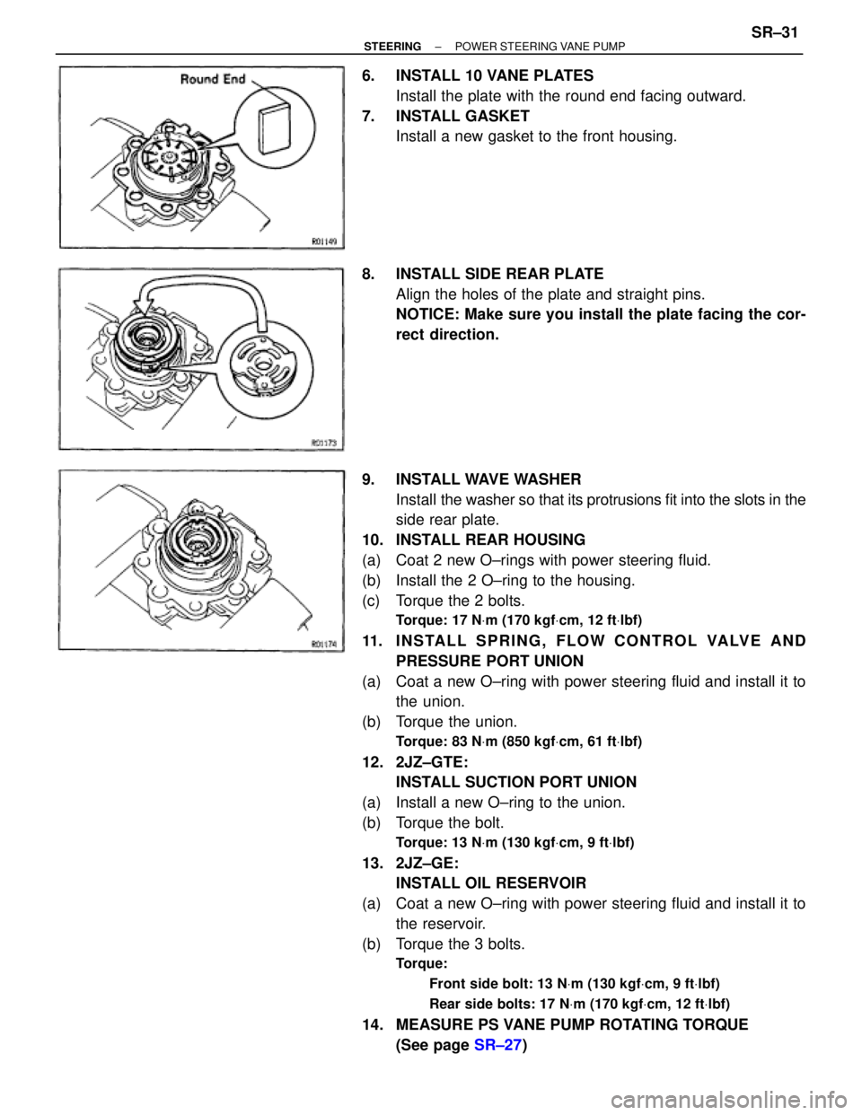
6. INSTALL 10 VANE PLATES
Install the plate with the round end facing outward.
7. INSTALL GASKET
Install a new gasket to the front housing.
8. INSTALL SIDE REAR PLATE
Align the holes of the plate and straight pins.
NOTICE: Make sure you install the plate facing the cor-
rect direction.
9. INSTALL WAVE WASHER
Install the washer so that its protrusions fit into the slots in the
side rear plate.
10. INSTALL REAR HOUSING
(a) Coat 2 new O±rings with power steering fluid.
(b) Install the 2 O±ring to the housing.
(c) Torque the 2 bolts.
Torque: 17 NVm (170 kgfVcm, 12 ftVlbf)
11. I N S TA L L S P R I N G , F L O W C O N T R O L VA LV E A N D
PRESSURE PORT UNION
(a) Coat a new O±ring with power steering fluid and install it to
the union.
(b) Torque the union.
Torque: 83 NVm (850 kgfVcm, 61 ftVlbf)
12. 2JZ±GTE:
INSTALL SUCTION PORT UNION
(a) Install a new O±ring to the union.
(b) Torque the bolt.
Torque: 13 NVm (130 kgfVcm, 9 ftVlbf)
13. 2JZ±GE:
INSTALL OIL RESERVOIR
(a) Coat a new O±ring with power steering fluid and install it to
the reservoir.
(b) Torque the 3 bolts.
Torque:
Front side bolt: 13 NVm (130 kgfVcm, 9 ftVlbf)
Rear side bolts: 17 NVm (170 kgfVcm, 12 ftVlbf)
14. MEASURE PS VANE PUMP ROTATING TORQUE
(See page SR±27)
± STEERINGPOWER STEERING VANE PUMPSR±31
Page 1670 of 2543
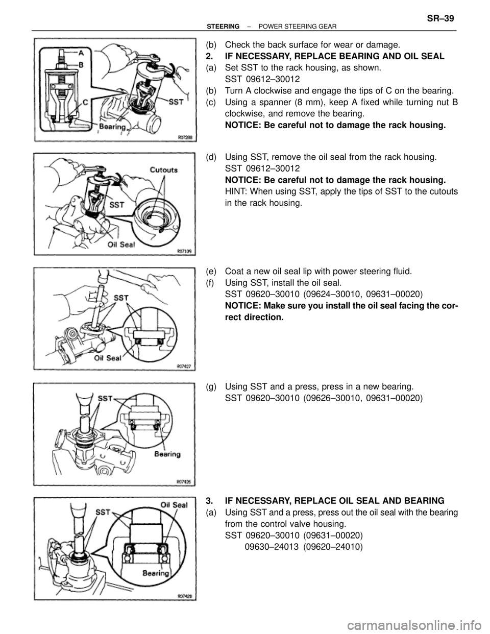
(b) Check the back surface for wear or damage.
2. IF NECESSARY, REPLACE BEARING AND OIL SEAL
(a) Set SST to the rack housing, as shown.
SST 09612±30012
(b) Turn A clockwise and engage the tips of C on the bearing.
(c) Using a spanner (8 mm), keep A fixed while turning nut B
clockwise, and remove the bearing.
NOTICE: Be careful not to damage the rack housing.
(d) Using SST, remove the oil seal from the rack housing.
SST 09612±30012
NOTICE: Be careful not to damage the rack housing.
HINT: When using SST, apply the tips of SST to the cutouts
in the rack housing.
(e) Coat a new oil seal lip with power steering fluid.
(f) Using SST, install the oil seal.
SST 09620±30010 (09624±30010, 09631±00020)
NOTICE: Make sure you install the oil seal facing the cor-
rect direction.
(g) Using SST and a press, press in a new bearing.
SST 09620±30010 (09626±30010, 09631±00020)
3. IF NECESSARY, REPLACE OIL SEAL AND BEARING
(a) Using SST and a press, press out the oil seal with the bearing
from the control valve housing.
SST 09620±30010 (09631±00020)
09630±24013 (09620±24010)
± STEERINGPOWER STEERING GEARSR±39
Page 1671 of 2543
(b) Coat a new oil seal lip with power steering fluid.
(c) Using SST and a press, press in the oil seal.
SST 09620±30010 (09631±00020)
09630±24013 (09620±24020)
NOTICE: Make sure you install the oil seal facing the cor-
rect direction.
(d) Using SST and a press, press in a new bearing.
SST 09620±30010 (09631±00020)
09630±24013 (09620±24030)
4. IF NECESSARY, REPLACE TEFLON RING AND O±RING
(a) Using a screwdriver, remove the teflon ring and O±ring.
NOTICE: Be careful not to damage the groove for the te-
flon ring.
(b) Coat a new O±ring with power steering fluid and install it.
(c) Expand a new teflon ring with your fingers.
NOTICE: Be careful not to over±expand the ring.
(d) Install the teflon ring to the rack.
(e) Coat the teflon ring with power steering fluid, and snug it
down with your fingers. SR±40
± STEERINGPOWER STEERING GEAR
Page 1672 of 2543
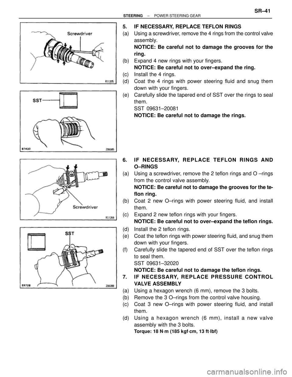
5. IF NECESSARY, REPLACE TEFLON RINGS
(a) Using a screwdriver, remove the 4 rings from the control valve
assembly.
NOTICE: Be careful not to damage the grooves for the
ring.
(b) Expand 4 new rings with your fingers.
NOTICE: Be careful not to over±expand the ring.
(c) Install the 4 rings.
(d) Coat the 4 rings with power steering fluid and snug them
down with your fingers.
(e) Carefully slide the tapered end of SST over the rings to seal
them.
SST 09631±20081
NOTICE: Be careful not to damage the rings.
6. IF NECESSARY, REPLACE TEFLON RINGS AND
O±RINGS
(a) Using a screwdriver, remove the 2 teflon rings and O ±rings
from the control valve assembly.
NOTICE: Be careful not to damage the grooves for the te-
flon ring.
(b) Coat 2 new O±rings with power steering fluid, and install
them.
(c) Expand 2 new teflon rings with your fingers.
NOTICE: Be careful not to over±expand the teflon rings.
(d) Install the 2 teflon rings.
(e) Coat the teflon rings with power steering fluid, and snug them
down with your fingers.
(f) Carefully slide the tapered end of SST over the teflon rings
to seal them.
SST 09631±32020
NOTICE: Be careful not to damage the teflon rings.
7. IF NECESSARY, REPLACE PRESSURE CONTROL
VALVE ASSEMBLY
(a) Using a hexagon wrench (6 mm), remove the 3 bolts.
(b) Remove the 3 O±rings from the control valve housing.
(c) Coat 3 new O±rings with power steering fluid, and install
them.
(d) Using a hexagon wrench (6 mm), install a new valve
assembly with the 3 bolts.
Torque: 18 NVm (185 kgfVcm, 13 ftVlbf)
± STEERINGPOWER STEERING GEARSR±41
Page 1673 of 2543
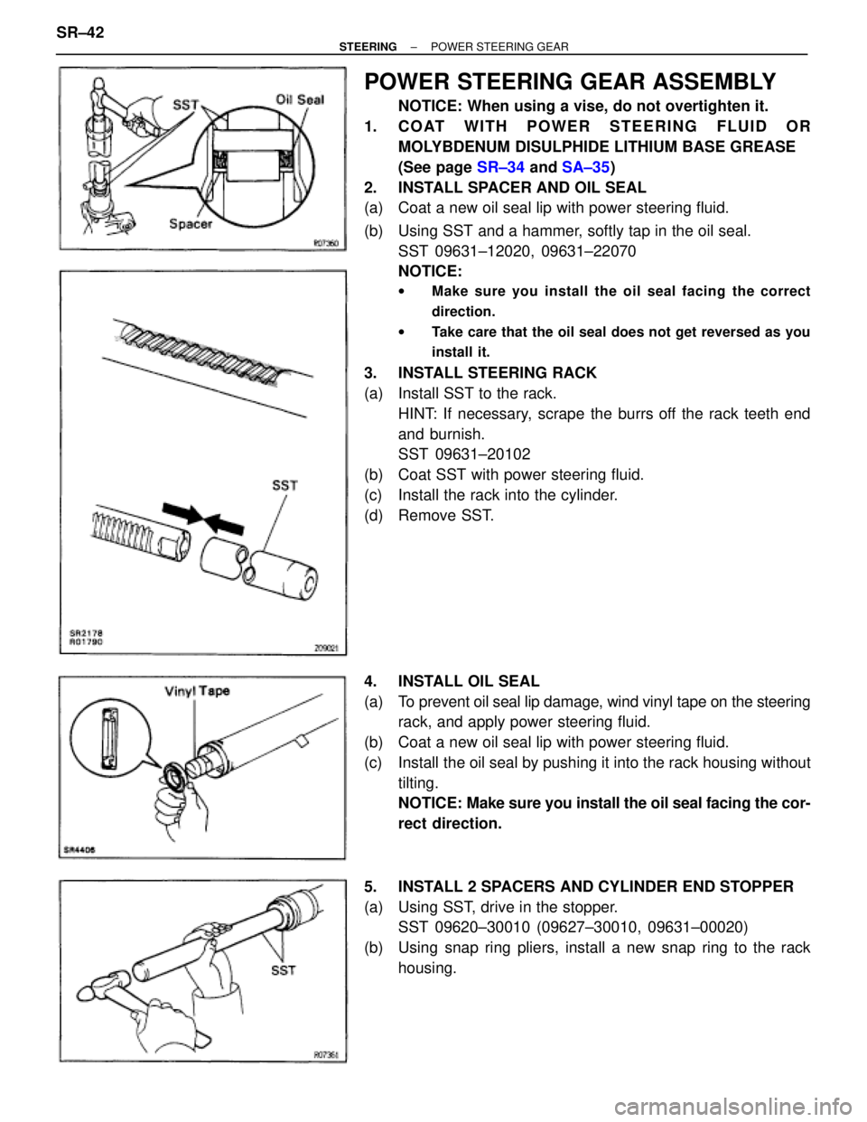
POWER STEERING GEAR ASSEMBLY
NOTICE: When using a vise, do not overtighten it.
1. COAT WITH POWER STEERING FLUID OR
MOLYBDENUM DISULPHIDE LITHIUM BASE GREASE
(See page SR±34 and SA±35)
2. INSTALL SPACER AND OIL SEAL
(a) Coat a new oil seal lip with power steering fluid.
(b) Using SST and a hammer, softly tap in the oil seal.
SST 09631±12020, 09631±22070
NOTICE:
wMake sure you install the oil seal facing the correct
direction.
wTake care that the oil seal does not get reversed as you
install it.
3. INSTALL STEERING RACK
(a) Install SST to the rack.
HINT: If necessary, scrape the burrs off the rack teeth end
and burnish.
SST 09631±20102
(b) Coat SST with power steering fluid.
(c) Install the rack into the cylinder.
(d) Remove SST.
4. INSTALL OIL SEAL
(a) To prevent oil seal lip damage, wind vinyl tape on the steering
rack, and apply power steering fluid.
(b) Coat a new oil seal lip with power steering fluid.
(c) Install the oil seal by pushing it into the rack housing without
tilting.
NOTICE: Make sure you install the oil seal facing the cor-
rect direction.
5. INSTALL 2 SPACERS AND CYLINDER END STOPPER
(a) Using SST, drive in the stopper.
SST 09620±30010 (09627±30010, 09631±00020)
(b) Using snap ring pliers, install a new snap ring to the rack
housing. SR±42
± STEERINGPOWER STEERING GEAR