Page 1369 of 2248
OBD0145A
1CONNECT SUBARU SELECT MONITOR OR
THE OBD-II GENERAL SCAN TOOL, AND
READ DATA.
1) Turn ignition switch to OFF.
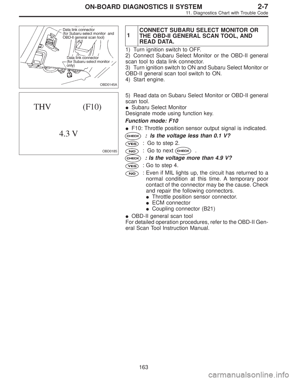
2) Connect Subaru Select Monitor or the OBD-II general
scan tool to data link connector.
3) Turn ignition switch to ON and Subaru Select Monitor or
OBD-II general scan tool switch to ON.
4) Start engine.
OBD0185
5) Read data on Subaru Select Monitor or OBD-II general
scan tool.
�Subaru Select Monitor
Designate mode using function key.
Function mode: F10
�F10: Throttle position sensor output signal is indicated.
: Is the voltage less than 0.1 V?
: Go to step 2.
: Go to next.
: Is the voltage more than 4.9 V?
: Go to step 4.
: Even if MIL lights up, the circuit has returned to a
normal condition at this time. A temporary poor
contact of the connector may be the cause. Check
and repair the following connectors.
�Throttle position sensor connector.
�ECM connector
�Coupling connector (B21)
�OBD-II general scan tool
For detailed operation procedures, refer to the OBD-II Gen-
eral Scan Tool Instruction Manual.
163
2-7ON-BOARD DIAGNOSTICS II SYSTEM
11. Diagnostics Chart with Trouble Code
Page 1496 of 2248
1.Check any other DTC (besides DTC P0740) on
display.
2.Check duty solenoid B circuit.
[T7B0]”.>
3.Check throttle position sensor circuit.
“3-2 [T7L0]”.>
4.Check vehicle speed sensor 1 circuit.
“3-2 [T7M0]”.>
5.Check vehicle speed sensor 2 circuit.
“3-2 [T7N0]”.>
6.Check engine speed input circuit.
[T7I0]”.>
7.Check inhibitor switch circuit.
DTC P0705 [T11AN0]”.>
8.Check brake light switch circuit.
DTC P0703 [T11AM0]”.>
9.Check ATF temperature sensor circuit.
“3-2 [T7G0]”.>
CAUTION:
After repair or replacement of faulty parts, conduct
CLEAR MEMORY and INSPECTION MODES.
[T3D0] and [T3E0].>
�
�
�
�
�
�
�
�
290
2-7ON-BOARD DIAGNOSTICS II SYSTEM
11. Diagnostics Chart with Trouble Code
Page 1557 of 2248
G3M0717
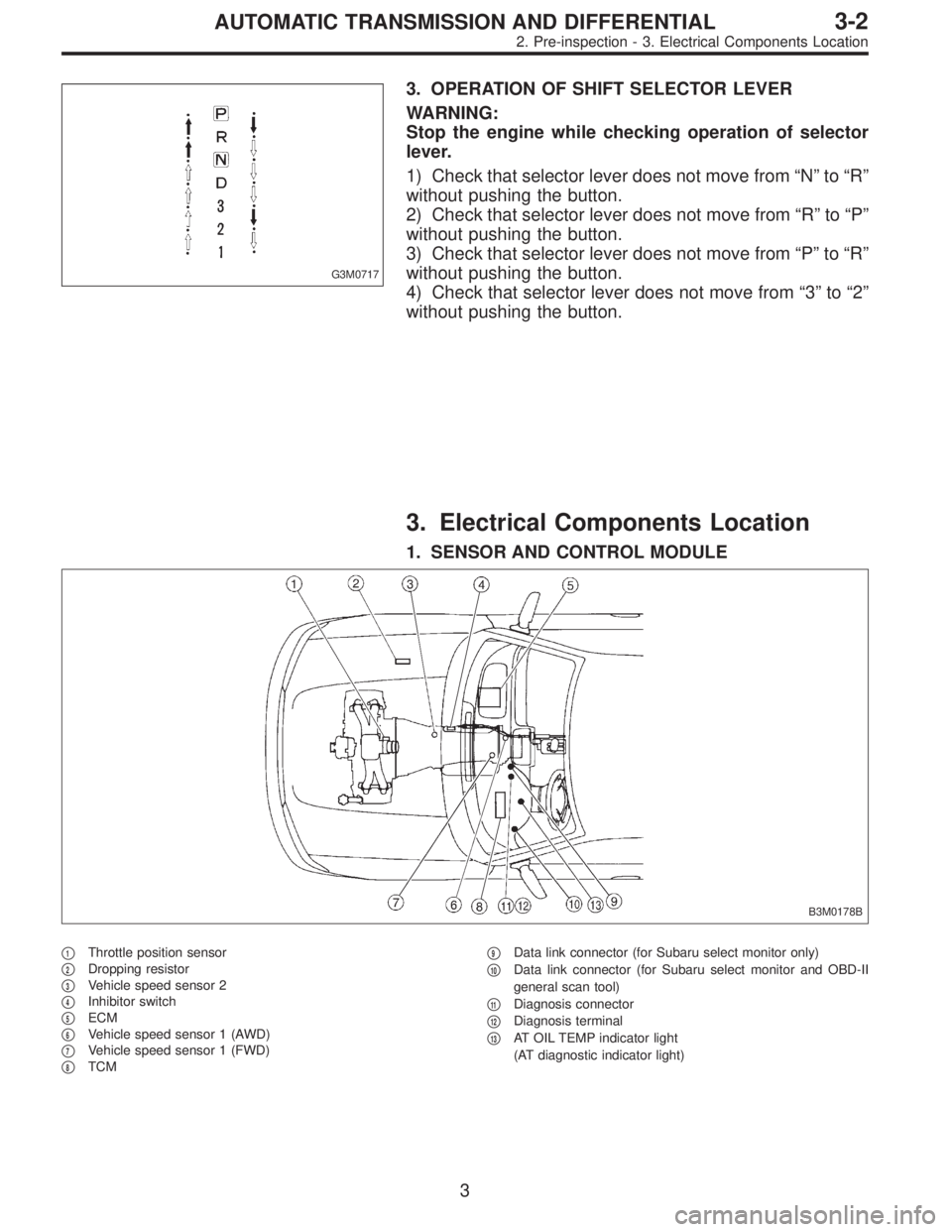
3. OPERATION OF SHIFT SELECTOR LEVER
WARNING:
Stop the engine while checking operation of selector
lever.
1) Check that selector lever does not move from“N”to“R”
without pushing the button.
2) Check that selector lever does not move from“R”to“P”
without pushing the button.
3) Check that selector lever does not move from“P”to“R”
without pushing the button.
4) Check that selector lever does not move from“3”to“2”
without pushing the button.
3. Electrical Components Location
1. SENSOR AND CONTROL MODULE
B3M0178B
�1Throttle position sensor
�
2Dropping resistor
�
3Vehicle speed sensor 2
�
4Inhibitor switch
�
5ECM
�
6Vehicle speed sensor 1 (AWD)
�
7Vehicle speed sensor 1 (FWD)
�
8TCM�
9Data link connector (for Subaru select monitor only)
�
10Data link connector (for Subaru select monitor and OBD-II
general scan tool)
�
11Diagnosis connector
�
12Diagnosis terminal
�
13AT OIL TEMP indicator light
(AT diagnostic indicator light)
3
3-2AUTOMATIC TRANSMISSION AND DIFFERENTIAL
2. Pre-inspection - 3. Electrical Components Location
Page 1558 of 2248
G3M0717
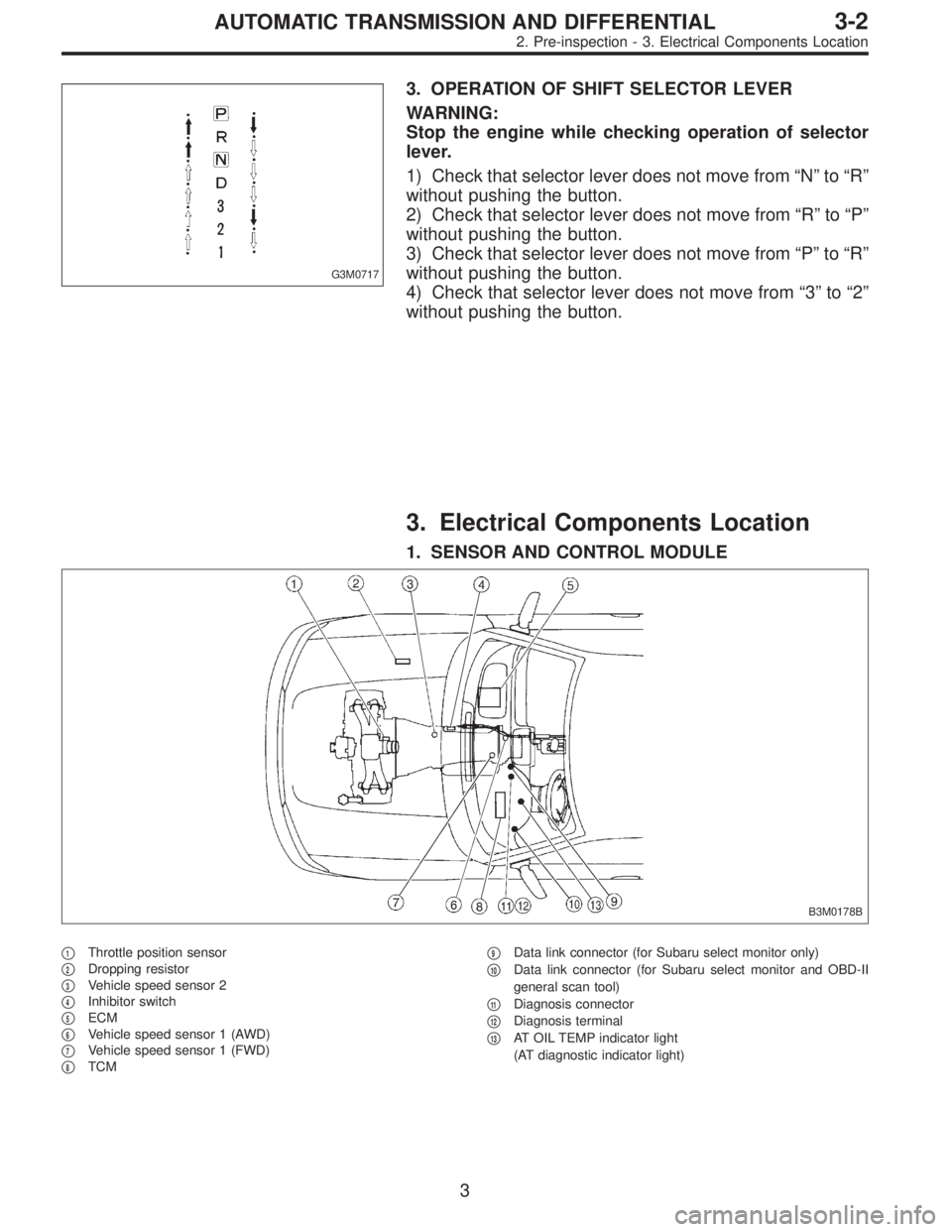
3. OPERATION OF SHIFT SELECTOR LEVER
WARNING:
Stop the engine while checking operation of selector
lever.
1) Check that selector lever does not move from“N”to“R”
without pushing the button.
2) Check that selector lever does not move from“R”to“P”
without pushing the button.
3) Check that selector lever does not move from“P”to“R”
without pushing the button.
4) Check that selector lever does not move from“3”to“2”
without pushing the button.
3. Electrical Components Location
1. SENSOR AND CONTROL MODULE
B3M0178B
�1Throttle position sensor
�
2Dropping resistor
�
3Vehicle speed sensor 2
�
4Inhibitor switch
�
5ECM
�
6Vehicle speed sensor 1 (AWD)
�
7Vehicle speed sensor 1 (FWD)
�
8TCM�
9Data link connector (for Subaru select monitor only)
�
10Data link connector (for Subaru select monitor and OBD-II
general scan tool)
�
11Diagnosis connector
�
12Diagnosis terminal
�
13AT OIL TEMP indicator light
(AT diagnostic indicator light)
3
3-2AUTOMATIC TRANSMISSION AND DIFFERENTIAL
2. Pre-inspection - 3. Electrical Components Location
Page 1576 of 2248
OBD0607A
4. CHECK OUTPUT SIGNAL EMITTED FROM TCM.
1) Connect connectors to TCM and transmission.
2) Lift-up the vehicle or set the vehicle on free roller.
CAUTION:
On AWD models, raise all wheels off floor.
3) Start and warm-up the engine and transmission.
4) Push the TCS OFF switch to ON. (With TCS models)
5) Move selector lever to“D”and slowly increase vehicle
speed to 75 km/h (47 MPH).
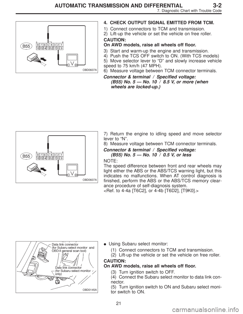
6) Measure voltage between TCM connector terminals.
Connector & terminal / Specified voltage:
(B55) No. 5—No. 10 / 8.5 V, or more (when
wheels are locked-up.)
OBD0607A
7) Return the engine to idling speed and move selector
lever to“N”.
8) Measure voltage between TCM connector terminals.
Connector & terminal / Specified voltage:
(B55) No. 5—No. 10 / 0.5 V, or less
NOTE:
The speed difference between front and rear wheels may
light either the ABS or the ABS/TCS warning light, but this
indicates no malfunctions. When AT control diagnosis is
finished, perform the ABS or the ABS/TCS memory clear-
ance procedure of self-diagnosis system.
OBD0145A
�Using Subaru select monitor:
(1) Connect connectors to TCM and transmission.
(2) Lift-up the vehicle or set the vehicle on free roller.
CAUTION:
On AWD models, raise all wheels off floor.
(3) Turn ignition switch to OFF.
(4) Connect the Subaru select monitor to data link con-
nector.
(5) Turn ignition switch to ON and Subaru select moni-
tor switch to ON.
21
3-2AUTOMATIC TRANSMISSION AND DIFFERENTIAL
7. Diagnostic Chart with Trouble Code
Page 1579 of 2248
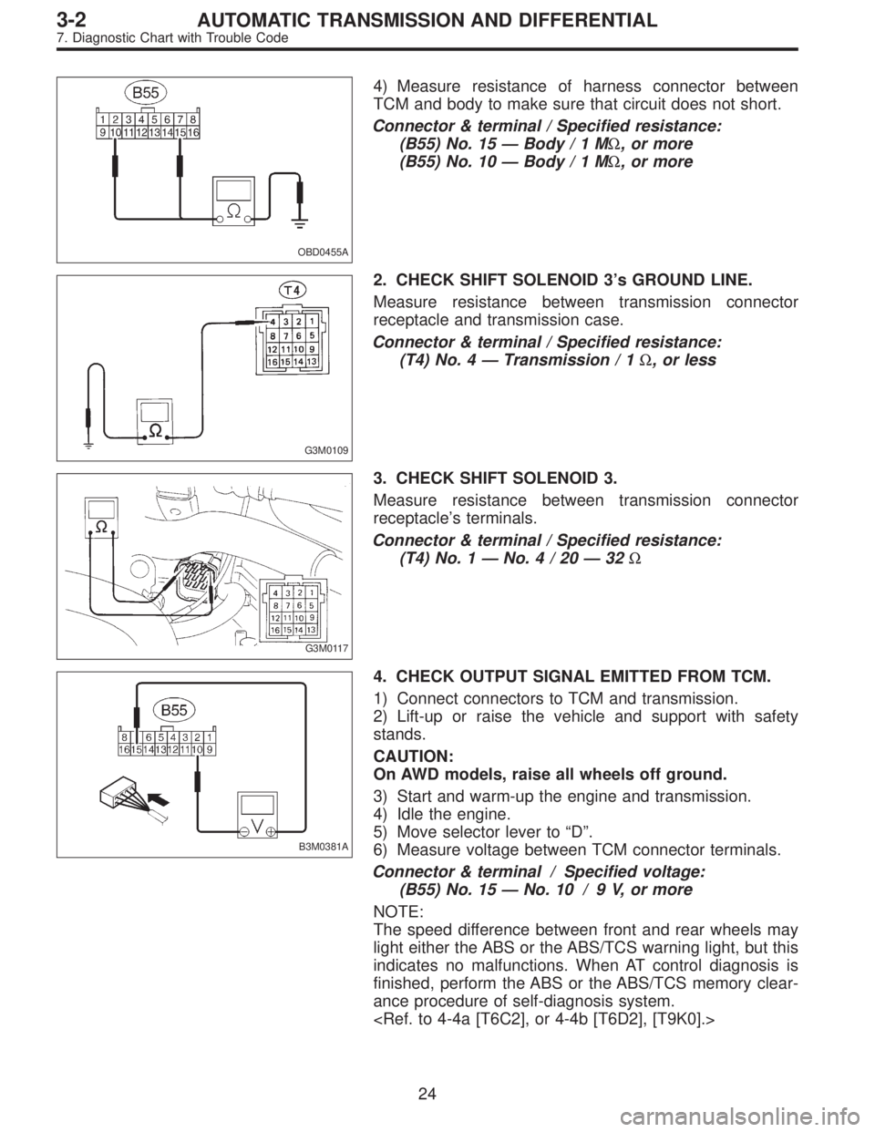
OBD0455A
4) Measure resistance of harness connector between
TCM and body to make sure that circuit does not short.
Connector & terminal / Specified resistance:
(B55) No. 15—Body/1MΩ, or more
(B55) No. 10—Body/1MΩ, or more
G3M0109
2. CHECK SHIFT SOLENOID 3’s GROUND LINE.
Measure resistance between transmission connector
receptacle and transmission case.
Connector & terminal / Specified resistance:
(T4) No. 4—Transmission / 1Ω, or less
G3M0117
3. CHECK SHIFT SOLENOID 3.
Measure resistance between transmission connector
receptacle’s terminals.
Connector & terminal / Specified resistance:
(T4) No. 1—No.4/20—32Ω
B3M0381A
4. CHECK OUTPUT SIGNAL EMITTED FROM TCM.
1) Connect connectors to TCM and transmission.
2) Lift-up or raise the vehicle and support with safety
stands.
CAUTION:
On AWD models, raise all wheels off ground.
3) Start and warm-up the engine and transmission.
4) Idle the engine.
5) Move selector lever to“D”.
6) Measure voltage between TCM connector terminals.
Connector & terminal / Specified voltage:
(B55) No. 15—No. 10 / 9 V, or more
NOTE:
The speed difference between front and rear wheels may
light either the ABS or the ABS/TCS warning light, but this
indicates no malfunctions. When AT control diagnosis is
finished, perform the ABS or the ABS/TCS memory clear-
ance procedure of self-diagnosis system.
24
3-2AUTOMATIC TRANSMISSION AND DIFFERENTIAL
7. Diagnostic Chart with Trouble Code
Page 1581 of 2248
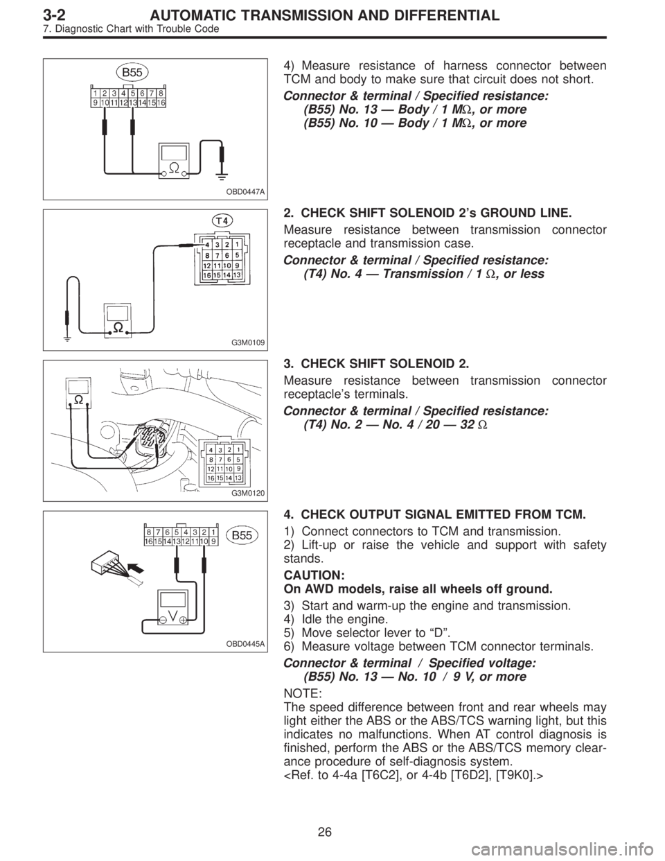
OBD0447A
4) Measure resistance of harness connector between
TCM and body to make sure that circuit does not short.
Connector & terminal / Specified resistance:
(B55) No. 13—Body/1MΩ, or more
(B55) No. 10—Body/1MΩ, or more
G3M0109
2. CHECK SHIFT SOLENOID 2’s GROUND LINE.
Measure resistance between transmission connector
receptacle and transmission case.
Connector & terminal / Specified resistance:
(T4) No. 4—Transmission / 1Ω, or less
G3M0120
3. CHECK SHIFT SOLENOID 2.
Measure resistance between transmission connector
receptacle’s terminals.
Connector & terminal / Specified resistance:
(T4) No. 2—No.4/20—32Ω
OBD0445A
4. CHECK OUTPUT SIGNAL EMITTED FROM TCM.
1) Connect connectors to TCM and transmission.
2) Lift-up or raise the vehicle and support with safety
stands.
CAUTION:
On AWD models, raise all wheels off ground.
3) Start and warm-up the engine and transmission.
4) Idle the engine.
5) Move selector lever to“D”.
6) Measure voltage between TCM connector terminals.
Connector & terminal / Specified voltage:
(B55) No. 13—No. 10 / 9 V, or more
NOTE:
The speed difference between front and rear wheels may
light either the ABS or the ABS/TCS warning light, but this
indicates no malfunctions. When AT control diagnosis is
finished, perform the ABS or the ABS/TCS memory clear-
ance procedure of self-diagnosis system.
26
3-2AUTOMATIC TRANSMISSION AND DIFFERENTIAL
7. Diagnostic Chart with Trouble Code
Page 1583 of 2248
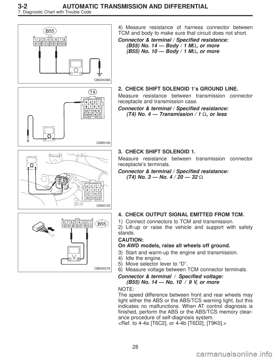
OBD0439A
4) Measure resistance of harness connector between
TCM and body to make sure that circuit does not short.
Connector & terminal / Specified resistance:
(B55) No. 14—Body/1MΩ, or more
(B55) No. 10—Body/1MΩ, or more
G3M0109
2. CHECK SHIFT SOLENOID 1’s GROUND LINE.
Measure resistance between transmission connector
receptacle and transmission case.
Connector & terminal / Specified resistance:
(T4) No. 4—Transmission / 1Ω, or less
G3M0123
3. CHECK SHIFT SOLENOID 1.
Measure resistance between transmission connector
receptacle’s terminals.
Connector & terminal / Specified resistance:
(T4) No. 3—No.4/20—32Ω
OBD0437A
4. CHECK OUTPUT SIGNAL EMITTED FROM TCM.
1) Connect connectors to TCM and transmission.
2) Lift-up or raise the vehicle and support with safety
stands.
CAUTION:
On AWD models, raise all wheels off ground.
3) Start and warm-up the engine and transmission.
4) Idle the engine.
5) Move selector lever to“D”.
6) Measure voltage between TCM connector terminals.
Connector & terminal / Specified voltage:
(B55) No. 14—No. 10 / 9 V, or more
NOTE:
The speed difference between front and rear wheels may
light either the ABS or the ABS/TCS warning light, but this
indicates no malfunctions. When AT control diagnosis is
finished, perform the ABS or the ABS/TCS memory clear-
ance procedure of self-diagnosis system.
28
3-2AUTOMATIC TRANSMISSION AND DIFFERENTIAL
7. Diagnostic Chart with Trouble Code
![SUBARU LEGACY 1995 Service Repair Manual 1.Check any other DTC (besides DTC P0740) on
display.
2.Check duty solenoid B circuit. <Ref. to“3-2
[T7B0]”.>
3.Check throttle position sensor circuit. <Ref. to
“3-2 [T7L0]”.>
4.Check vehicle](/manual-img/17/57432/w960_57432-1495.png "SUBARU LEGACY 1995 Service Repair Manual 1.Check any other DTC (besides DTC P0740) on
display.
2.Check duty solenoid B circuit. <Ref. to“3-2
[T7B0]”.>
3.Check throttle position sensor circuit. <Ref. to
“3-2 [T7L0]”.>
4.Check vehicle")