Page 1072 of 2248
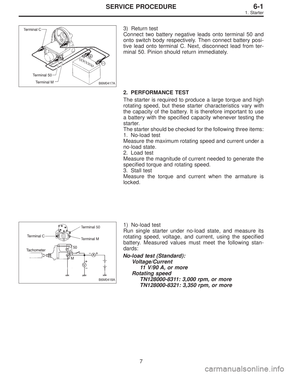
B6M0417A
3) Return test
Connect two battery negative leads onto terminal 50 and
onto switch body respectively. Then connect battery posi-
tive lead onto terminal C. Next, disconnect lead from ter-
minal 50. Pinion should return immediately.
2. PERFORMANCE TEST
The starter is required to produce a large torque and high
rotating speed, but these starter characteristics vary with
the capacity of the battery. It is therefore important to use
a battery with the specified capacity whenever testing the
starter.
The starter should be checked for the following three items:
1. No-load test
Measure the maximum rotating speed and current under a
no-load state.
2. Load test
Measure the magnitude of current needed to generate the
specified torque and rotating speed.
3. Stall test
Measure the torque and current when the armature is
locked.
B6M0418A
1) No-load test
Run single starter under no-load state, and measure its
rotating speed, voltage, and current, using the specified
battery. Measured values must meet the following stan-
dards:
No-load test (Standard):
Voltage/Current
11 V/90 A, or more
Rotating speed
TN128000-8311: 3,000 rpm, or more
TN128000-8321: 3,350 rpm, or more
7
6-1SERVICE PROCEDURE
1. Starter
Page 1100 of 2248
B: INSPECTION
1. BATTERY
1) External parts
Check for the existence of dirt or cracks on the battery
case, top cover, vent plugs, and terminal posts. If
necessary, clean with water and wipe with a dry cloth.
Apply a thin coat of grease on the terminal posts to prevent
corrosion.
2) Electrolyte level
Check the electrolyte level in each cell. If the level is below
MIN LEVEL, bring the level to MAX LEVEL by pouring dis-
tilled water into the battery cell. Do not fill beyond MAX
LEVEL.
WARNING:
�Electrolyte has toxicity; be careful handling the
fluid.
�Avoid contact with skin, eyes or clothing. Especially
at contact with eyes, blush with water for 15 minutes
and get prompt medical attention.
�Batteries produce explosive gasses. Keep sparks,
flame, cigarettes away.
�Ventilate when charging or using in enclosed space.
�For safety, in case an explosion does occur, wear
eye protection or shield your eyes when working near
any battery. Never lean over a battery.
�Do not let battery fluid contact eyes, skin, fabrics, or
paint-work because battery fluid is corrosive acid.
�To lessen the risk of sparks, remove rings, metal
watch-bands, and other metal jewelry. Never allow
metal tools to contact the positive battery terminal and
anything connected to it while you are at the same time
in contact with any other metallic portion of the vehicle
because a short circuit will be caused.
5
6-2SERVICE PROCEDURE
2. Battery
Page 1109 of 2248
B6M0238
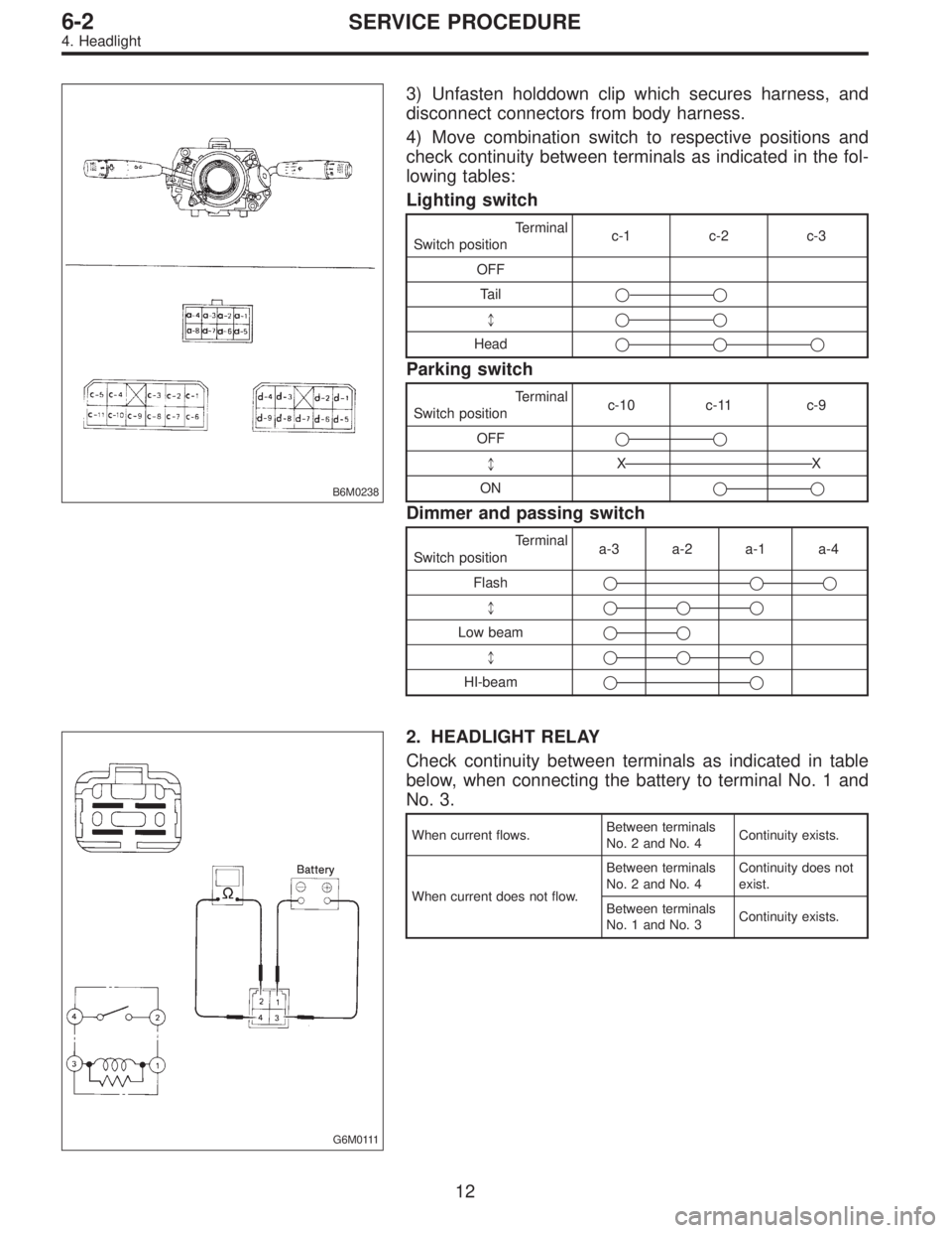
3) Unfasten holddown clip which secures harness, and
disconnect connectors from body harness.
4) Move combination switch to respective positions and
check continuity between terminals as indicated in the fol-
lowing tables:
Lighting switch
Terminal
Switch positionc-1 c-2 c-3
OFF
Tail��
*��
Head���
Parking switch
Terminal
Switch positionc-10 c-11 c-9
OFF��
*XX
ON��
Dimmer and passing switch
Terminal
Switch positiona-3 a-2 a-1 a-4
Flash��
�
*���
Low beam��
*���
HI-beam��
G6M0111
2. HEADLIGHT RELAY
Check continuity between terminals as indicated in table
below, when connecting the battery to terminal No. 1 and
No. 3.
When current flows.Between terminals
No. 2 and No. 4Continuity exists.
When current does not flow.Between terminals
No. 2 and No. 4Continuity does not
exist.
Between terminals
No. 1 and No. 3Continuity exists.
12
6-2SERVICE PROCEDURE
4. Headlight
Page 1116 of 2248
B: DISASSEMBLY AND ASSEMBLY
1. COMBINATION SWITCH
Refer to 6-2 [W4C1] as for disassembly and assembly of
combination switch.
C: INSPECTION
1. COMBINATION SWITCH (ON-CAR)
1) Remove instrument panel lower cover.
2) Remove lower column cover.
B6M0238
3) Unfasten holddown clip which secures harness, and
disconnect connectors from body harness.
4) Move combination switch to respective positions and
check continuity between terminals as indicated in table
below:
Turn signal switch
Terminal
Switch positiona-5 a-7 a-6
TurnL⋅L′��
*xx
N
*xx
R⋅R′��
B6M0344
2. HAZARD SWITCH
Move hazard switch to each position and check continuity
between terminals as indicated in table below:
73910561 2
ON��
�����
OFF����
19
6-2SERVICE PROCEDURE
6. Turn Signal and Hazard Warning Light
Page 1244 of 2248
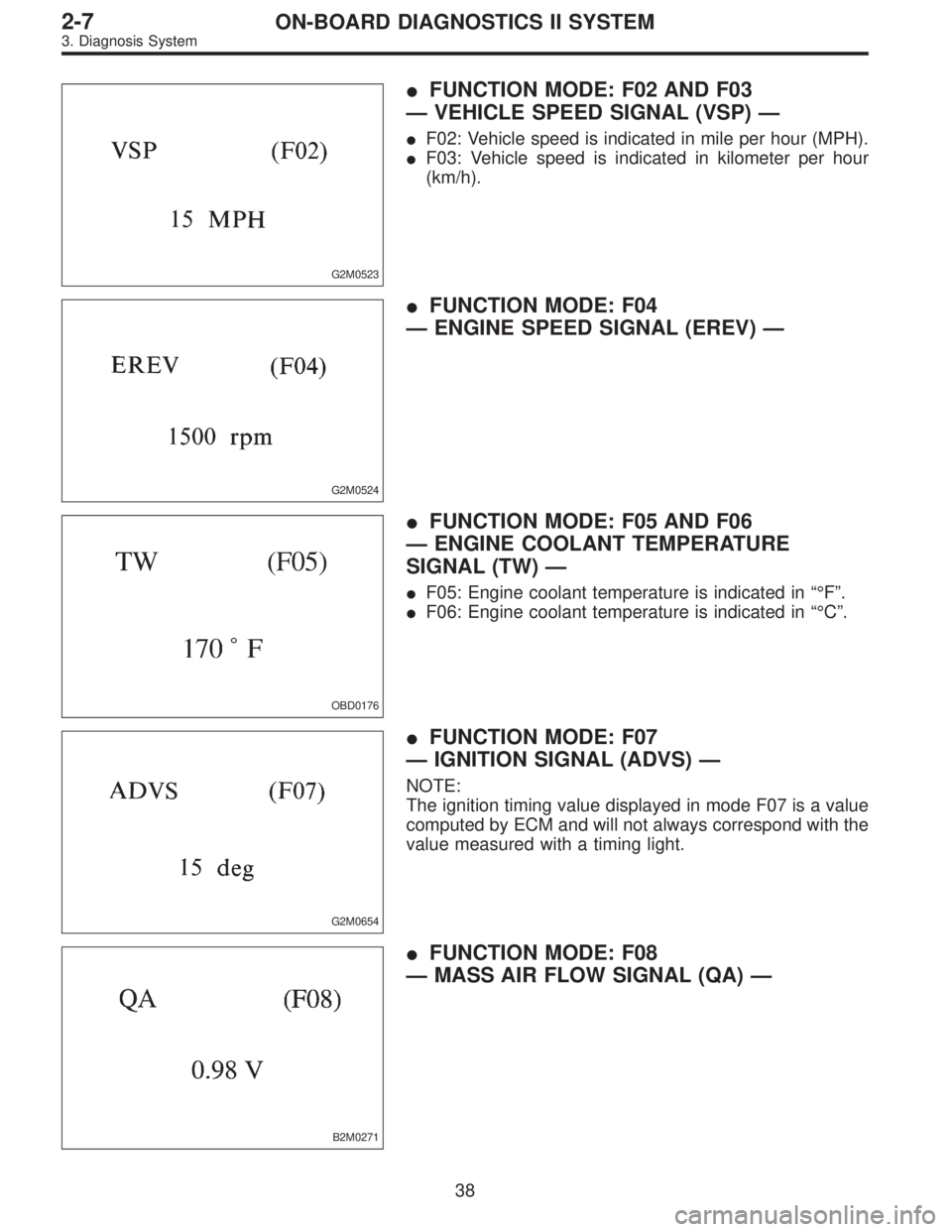
G2M0523
�FUNCTION MODE: F02 AND F03
—VEHICLE SPEED SIGNAL (VSP)—
�F02: Vehicle speed is indicated in mile per hour (MPH).
�F03: Vehicle speed is indicated in kilometer per hour
(km/h).
G2M0524
�FUNCTION MODE: F04
—ENGINE SPEED SIGNAL (EREV)—
OBD0176
�FUNCTION MODE: F05 AND F06
—ENGINE COOLANT TEMPERATURE
SIGNAL (TW)—
�F05: Engine coolant temperature is indicated in“°F”.
�F06: Engine coolant temperature is indicated in“°C”.
G2M0654
�FUNCTION MODE: F07
—IGNITION SIGNAL (ADVS)—
NOTE:
The ignition timing value displayed in mode F07 is a value
computed by ECM and will not always correspond with the
value measured with a timing light.
B2M0271
�FUNCTION MODE: F08
—MASS AIR FLOW SIGNAL (QA)—
38
2-7ON-BOARD DIAGNOSTICS II SYSTEM
3. Diagnosis System
Page 1254 of 2248
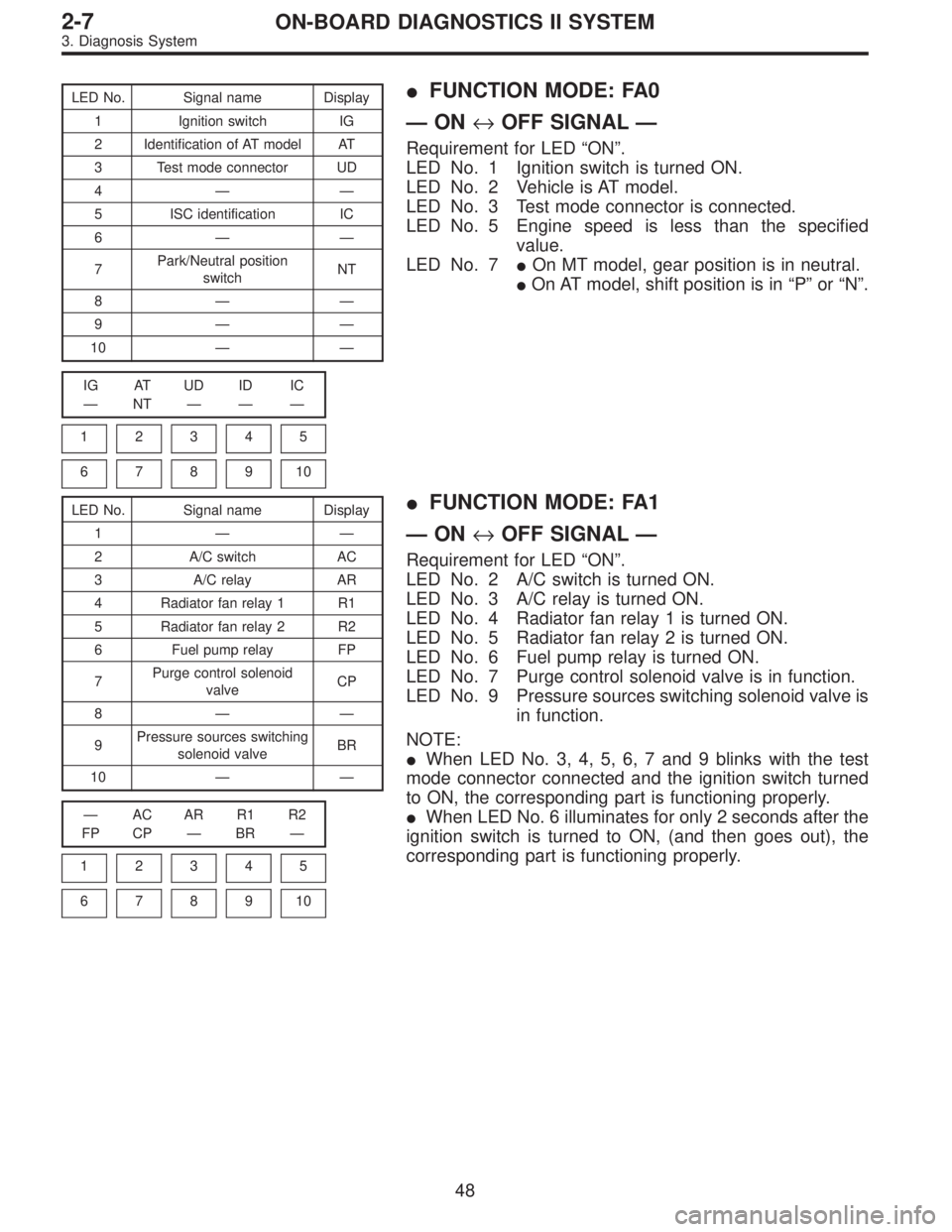
LED No. Signal name Display
1 Ignition switch IG
2 Identification of AT model AT
3 Test mode connector UD
4——
5 ISC identification IC
6——
7Park/Neutral position
switchNT
8——
9——
10——
IG AT UD ID IC
—NT———
1
2345
678910
�FUNCTION MODE: FA0
—ON↔OFF SIGNAL—
Requirement for LED“ON”.
LED No. 1 Ignition switch is turned ON.
LED No. 2 Vehicle is AT model.
LED No. 3 Test mode connector is connected.
LED No. 5 Engine speed is less than the specified
value.
LED No. 7�On MT model, gear position is in neutral.
�On AT model, shift position is in“P”or“N”.
LED No. Signal name Display
1——
2 A/C switch AC
3 A/C relay AR
4 Radiator fan relay 1 R1
5 Radiator fan relay 2 R2
6 Fuel pump relay FP
7Purge control solenoid
valveCP
8——
9Pressure sources switching
solenoid valveBR
10——
—AC AR R1 R2
FP CP—BR—
1
2345
678910
�FUNCTION MODE: FA1
—ON↔OFF SIGNAL—
Requirement for LED“ON”.
LED No. 2 A/C switch is turned ON.
LED No. 3 A/C relay is turned ON.
LED No. 4 Radiator fan relay 1 is turned ON.
LED No. 5 Radiator fan relay 2 is turned ON.
LED No. 6 Fuel pump relay is turned ON.
LED No. 7 Purge control solenoid valve is in function.
LED No. 9 Pressure sources switching solenoid valve is
in function.
NOTE:
�When LED No. 3, 4, 5, 6, 7 and 9 blinks with the test
mode connector connected and the ignition switch turned
to ON, the corresponding part is functioning properly.
�When LED No. 6 illuminates for only 2 seconds after the
ignition switch is turned to ON, (and then goes out), the
corresponding part is functioning properly.
48
2-7ON-BOARD DIAGNOSTICS II SYSTEM
3. Diagnosis System
Page 1339 of 2248
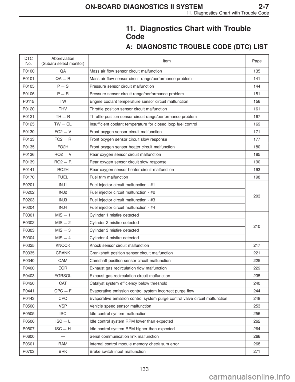
11. Diagnostics Chart with Trouble
Code
A: DIAGNOSTIC TROUBLE CODE (DTC) LIST
DTC
No.Abbreviation
(Subaru select monitor)Item Page
P0100 QA Mass air flow sensor circuit malfunction 135
P0101 QA
—R Mass air flow sensor circuit range/performance problem 141
P0105 P
—S Pressure sensor circuit malfunction 144
P0106 P
—R Pressure sensor circuit range/performance problem 151
P0115 TW Engine coolant temperature sensor circuit malfunction 156
P0120 THV Throttle position sensor circuit malfunction 161
P0121 TH
—R Throttle position sensor circuit range/performance problem 167
P0125 TW
—CL Insufficient coolant temperature for closed loop fuel control 169
P0130 FO2
—V Front oxygen sensor circuit malfunction 171
P0133 FO2
—R Front oxygen sensor circuit slow response 177
P0135 FO2H Front oxygen sensor heater circuit malfunction 180
P0136 RO2
—V Rear oxygen sensor circuit malfunction 185
P0139 RO2
—R Rear oxygen sensor circuit slow response 190
P0141 RO2H Rear oxygen sensor heater circuit malfunction 193
P0170 FUEL Fuel trim malfunction 198
P0201 INJ1 Fuel injector circuit malfunction - #1
203 P0202 INJ2 Fuel injector circuit malfunction - #2
P0203 INJ3 Fuel injector circuit malfunction - #3
P0204 INJ4 Fuel injector circuit malfunction - #4
P0301 MIS
—1 Cylinder 1 misfire detected
210 P0302 MIS
—2 Cylinder 2 misfire detected
P0303 MIS
—3 Cylinder 3 misfire detected
P0304 MIS
—4 Cylinder 4 misfire detected
P0325 KNOCK Knock sensor circuit malfunction 217
P0335 CRANK Crankshaft position sensor circuit malfunction 221
P0340 CAM Camshaft position sensor circuit malfunction 225
P0400 EGR Exhaust gas recirculation flow malfunction 229
P0403 EGRSOL Exhaust gas recirculation circuit malfunction 235
P0420 CAT Catalyst system efficiency below threshold 240
P0441 CPC
—F Evaporative emission control system incorrect purge flow 244
P0443 CPC Evaporative emission control system purge control valve circuit malfunction 248
P0500 VSP Vehicle speed sensor malfunction 253
P0505 ISC Idle control system malfunction 256
P0506 ISC
—L Idle control system RPM lower than expected 262
P0507 ISC
—H Idle control system RPM higher than expected 264
P0600—Serial communication link malfunction 266
P0601 RAM Internal control module memory check sum error 268
P0703 BRK Brake switch input malfunction 271
133
2-7ON-BOARD DIAGNOSTICS II SYSTEM
11. Diagnostics Chart with Trouble Code
Page 1341 of 2248
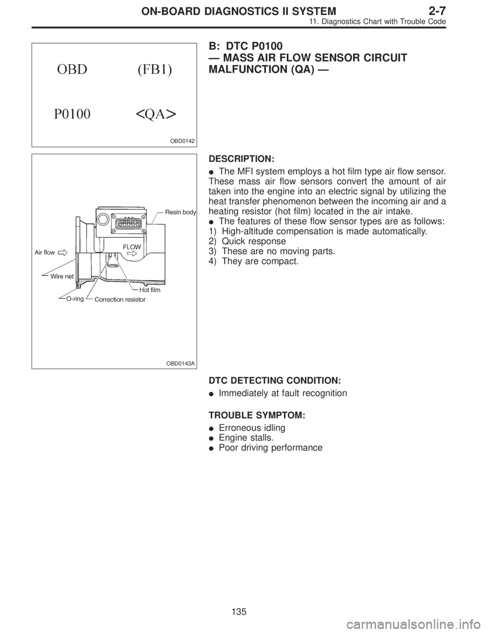
OBD0142
B: DTC P0100
—MASS AIR FLOW SENSOR CIRCUIT
MALFUNCTION (QA)—
OBD0143A
DESCRIPTION:
�The MFI system employs a hot film type air flow sensor.
These mass air flow sensors convert the amount of air
taken into the engine into an electric signal by utilizing the
heat transfer phenomenon between the incoming air and a
heating resistor (hot film) located in the air intake.
�The features of these flow sensor types are as follows:
1) High-altitude compensation is made automatically.
2) Quick response
3) These are no moving parts.
4) They are compact.
DTC DETECTING CONDITION:
�Immediately at fault recognition
TROUBLE SYMPTOM:
�Erroneous idling
�Engine stalls.
�Poor driving performance
135
2-7ON-BOARD DIAGNOSTICS II SYSTEM
11. Diagnostics Chart with Trouble Code
![SUBARU LEGACY 1995 Service Repair Manual B: DISASSEMBLY AND ASSEMBLY
1. COMBINATION SWITCH
Refer to 6-2 [W4C1] as for disassembly and assembly of
combination switch.
C: INSPECTION
1. COMBINATION SWITCH (ON-CAR)
1) Remove instrument panel low](/manual-img/17/57432/w960_57432-1115.png "SUBARU LEGACY 1995 Service Repair Manual B: DISASSEMBLY AND ASSEMBLY
1. COMBINATION SWITCH
Refer to 6-2 [W4C1] as for disassembly and assembly of
combination switch.
C: INSPECTION
1. COMBINATION SWITCH (ON-CAR)
1) Remove instrument panel low")