Page 1318 of 2248
C: CONTROL MODULE POWER SUPPLY AND
GROUND LINE
1.Check main relay.
2.Check power supply circuit of ECM.
3.Check ground circuit of ECM.
CAUTION:
After repair or replacement of faulty parts, conduct
CLEAR MEMORY and INSPECTION MODES.
[T3D0] and [T3E0].>
WIRING DIAGRAM:
�LHD model
OBD0105
�
�
11 2
2-7ON-BOARD DIAGNOSTICS II SYSTEM
9. Diagnostics for Engine Starting Failure
Page 1319 of 2248
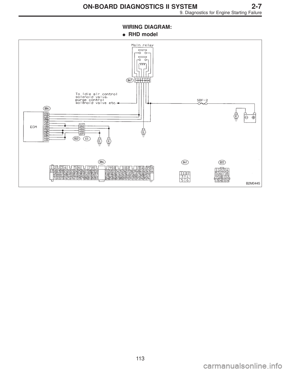
WIRING DIAGRAM:
�RHD model
B2M0445
11 3
2-7ON-BOARD DIAGNOSTICS II SYSTEM
9. Diagnostics for Engine Starting Failure
Page 1320 of 2248
G2M0444
1
CHECK MAIN RELAY.
1) Turn the ignition switch to OFF.
2) Remove main relay.
3) Connect battery to main relay terminals No. 1 and No.
2.
4) Measure resistance between main relay terminals.
: Terminals
No. 3—No. 5/10Ω, or less
No. 4—No. 6/10Ω, or less
: Go to step 2.
: Replace main relay.
OBD0107A
2
CHECK POWER SUPPLY CIRCUIT OF ECM.
1) Install main relay.
2) Disconnect connectors from ECM.
3) Turn ignition switch to ON.
4) Measure power supply voltage between ECM connec-
tor terminals.
: Connector & terminal
(B84) No. 15—No. 96/10 V, or more
(B84) No. 16—No. 96/10 V, or more
(B84) No. 42—No. 96/10 V, or more
: Go to step 3.
: Repair harness of power supply circuit.
11 4
2-7ON-BOARD DIAGNOSTICS II SYSTEM
9. Diagnostics for Engine Starting Failure
Page 1321 of 2248
OBD0108A
3
CHECK GROUND CIRCUIT OF ECM.
1) Turn ignition switch to OFF.
2) Measure resistance of harness connector between
ECM and body.
: Connector & terminal
(B84) No. 25—Body/10Ω, or less
(B84) No. 45—Body/10Ω, or less
(B84) No. 46—Body/10Ω, or less
(B84) No. 69—Body/10Ω, or less
(B84) No. 70—Body/10Ω, or less
(B84) No. 71—Body/10Ω, or less
(B84) No. 72—Body/10Ω, or less
(B84) No. 95—Body/10Ω, or less
(B84) No. 96—Body/10Ω, or less
: Check ignition control system.
[T9D0]”.>
: Repair harness between ECM connector and
body.
11 5
2-7ON-BOARD DIAGNOSTICS II SYSTEM
9. Diagnostics for Engine Starting Failure
Page 1322 of 2248
D: IGNITION CONTROL SYSTEM
1.Check ignition system for sparks.
2.Check power supply circuit for ignition coil.
3.Check ignition coil.
4.Check harness connector between ignitor and
ignition coil.
5.Check input signal for ignitor.
6.Check harness connector of ignitor ground
circuit.
7.Check harness connector between ECM and
ignitor.
CAUTION:
After repair or replacement of faulty parts, conduct
CLEAR MEMORY and INSPECTION MODES.
[T3D0] and [T3E0].>
WIRING DIAGRAM:
B2M0622
�
�
�
�
�
�
11 6
2-7ON-BOARD DIAGNOSTICS II SYSTEM
9. Diagnostics for Engine Starting Failure
Page 1323 of 2248
 Remove plug cord cap from each spark plug.
2) Install new spark plug on plug cord cap.
CAUTION:
Do not remove spark plug from engine.
3) Contact spark pl")
OBD0727
1
CHECK IGNITION SYSTEM FOR SPARKS.
1) Remove plug cord cap from each spark plug.
2) Install new spark plug on plug cord cap.
CAUTION:
Do not remove spark plug from engine.
3) Contact spark plug’s thread portion on engine.
4) While opening throttle valve fully, crank engine to check
that spark occurs at each cylinder.
: Does spark occur at each cylinder?
: Check fuel pump system.
: Go to step 2.
OBD0123A
2CHECK POWER SUPPLY CIRCUIT FOR IGNI-
TION COIL.
1) Turn ignition switch to OFF.
2) Disconnect connector from ignition coil.
3) Turn ignition switch to ON.
4) Measure power supply voltage between ignition coil
connector terminal and body.
: Connector & terminal
(E12) No. 2—Body /10 V, or more
: Go to step 3.
: Repair harness between ignition coil and ignition
switch connector.
OBD0124
3
CHECK IGNITION COIL.
1) Measure resistance between ignition coil terminals to
check primary coil.
: Terminals
No. 2—No. 1/0.7±0.3Ω
No. 2—No. 3/0.7±0.3Ω
: Replace ignition coil.
: Go to next step.
11 7
2-7ON-BOARD DIAGNOSTICS II SYSTEM
9. Diagnostics for Engine Starting Failure
Page 1324 of 2248
 Measure resistance between spark plug cord contact
portions to check secondary coil.
: Connector & terminal
#1—#2 /21±3 kΩ
#3—#4 /21±3 kΩ
: Go to step 4.
: Replace ignition coil.")
OBD0125A
2) Measure resistance between spark plug cord contact
portions to check secondary coil.
: Connector & terminal
#1—#2 /21±3 kΩ
#3—#4 /21±3 kΩ
: Go to step 4.
: Replace ignition coil.
OBD0126A
4CHECK HARNESS CONNECTOR BETWEEN
IGNITOR AND IGNITION COIL.
1) Turn ignition switch to OFF.
2) Disconnect connector from ignitor.
3) Measure resistance of harness connector between igni-
tion coil and ignitor.
: Connector & terminal
(B13) No. 5—(E12) No. 1/10Ω, or less
(B13) No. 6—(E12) No. 3/10Ω, or less
: Go to step 5.
: Go to next.
: Is there poor contact in coupling connector
(B22)?
: Repair poor contact in coupling connector.
: Repair harness between ignition coil and ignitor
connector.
OBD0728
5
CHECK INPUT SIGNAL FOR IGNITOR.
Check if voltage varies synchronously with engine speed
when cranking, while monitoring voltage between ignitor
connector and body.
: Connector & terminal:
(B13) No. 1—Body/10 V, or more
(B13) No. 2—Body/10 V, or more
: Go to step 6.
: Replace ignitor.
B2M0224A
11 8
2-7ON-BOARD DIAGNOSTICS II SYSTEM
9. Diagnostics for Engine Starting Failure
Page 1325 of 2248
 Turn ignition switch to OFF.
2) Measure resistance between ignitor and body.
: Connector & terminal
(B13) No. 3—Body /10Ω, or less
:")
OBD0128A
6CHECK HARNESS CONNECTOR OF IGNITOR
GROUND CIRCUIT.
1) Turn ignition switch to OFF.
2) Measure resistance between ignitor and body.
: Connector & terminal
(B13) No. 3—Body /10Ω, or less
: Go to step 7.
: Repair harness between ignitor connector and
body.
OBD0129A
7CHECK HARNESS CONNECTOR BETWEEN
ECM AND IGNITOR.
1) Disconnect connector from ECM.
2) Measure resistance of harness connector between
ECM and ignitor.
: Connector & terminal
(B84) No. 14—(B13) No. 1/10Ω, or less
(B84) No. 13—(B13) No. 2/10Ω, or less
(B84) No. 69—(B13) No. 3/10Ω, or less
: Repair open circuit of harness between ECM and
ignitor connector.
: Go to next step.
OBD0130A
3) Measure resistance of harness connector between
ECM and body.
: Connector & terminal
(B84) No. 13—Body/1 MΩ, or more
(B84) No. 14—Body/1 MΩ, or more
: Repair short circuit of harness between ECM and
ignitor.
: Confirm good connection in ECM connector.
11 9
2-7ON-BOARD DIAGNOSTICS II SYSTEM
9. Diagnostics for Engine Starting Failure

 Turn the ignition switch to OFF.
2) Remove main relay.
3) Connect battery to main relay terminals No. 1 and No.
2.
4) Measure resistance between main relay terminals.
:")
 Turn ignition switch to OFF.
2) Measure resistance of harness connector between
ECM and body.
: Connector & terminal
(B84) No. 25—Body/10Ω, or less
(B84)")
