Page 1277 of 2248
 I/O
SIGNAL
OBD0093A
Check with ignition switch ON.
ContentConnector
No.Terminal
No.Measuring conditions Voltage (V)
Back-up power supply B56 14 Ignition switch OFF")
3. TRANSMISSION CONTROL MODULE (TCM) I/O
SIGNAL
OBD0093A
Check with ignition switch ON.
ContentConnector
No.Terminal
No.Measuring conditions Voltage (V)
Back-up power supply B56 14 Ignition switch OFF 10—16
Ignition power supplyB54 6
Ignition switch ON (with engine OFF) 10—16
B55 1
Inhibitor switch“P”range switch B56 9Selector lever in“P”range Less than 1
Selector lever in any other than“P”
rangeMore than 8
“N”range switch B56 8Selector lever in“N”range Less than 1
Selector lever in any other than“N”
rangeMore than 8
“R”range switch B56 10Selector lever in“R”range Less than 1
Selector lever in any other than“R”
rangeMore than 6
“D”range switch B54 1Selector lever in“D”range Less than 1
Selector lever in any other than“D”
rangeMore than 6
“3”range switch B54 2Selector lever in“3”range Less than 1
Selector lever in any other than“3”
rangeMore than 6
“2”range switch B54 3Selector lever in“2”range Less than 1
Selector lever in any other than“2”
rangeMore than 6
“1”range switch B54 4Selector lever in“1”range Less than 1
Selector lever in any other than“1”
rangeMore than 6
Brake switch B56 7Brake pedal depressed More than 10.5
Brake pedal released Less than 1
ABS signal B56 5ABS switch ON Less than 1
ABS switch OFF More than 6.5
AT diagnostics signal B55 12Ignition switch ON (with engine OFF) Less than 1
Ignition switch ON (with engine ON) More than 10
Diagnosis switch B56 6Diagnosis connector connected. Less than 1
Diagnosis connector disconnected. More than 6
71
2-7ON-BOARD DIAGNOSTICS II SYSTEM
5. Specified Data
Page 1306 of 2248
![SUBARU LEGACY 1995 Service Repair Manual 7. Basic Diagnostics Procedure
Trouble occurs.
Ask the customer when and how the
trouble occurred using interview
check list. <Ref. to [T702].>
Start the engine.
Ye s�NoInspection using“9. Diagnosti](/manual-img/17/57432/w960_57432-1305.png "SUBARU LEGACY 1995 Service Repair Manual 7. Basic Diagnostics Procedure
Trouble occurs.
Ask the customer when and how the
trouble occurred using interview
check list. <Ref. to [T702].>
Start the engine.
Ye s�NoInspection using“9. Diagnosti")
7. Basic Diagnostics Procedure
Trouble occurs.
Ask the customer when and how the
trouble occurred using interview
check list.
Start the engine.
Ye s�NoInspection using“9. Diagnostics for
Engine Start Failure [T900]”
Malfunction indicator lamp (MIL) illu-
minates.
Ye s�NoInspection using“10. General Diag-
nostics Table [T1000]”
Inspection using Subaru select moni-
tor or OBD-II general scan tool.
(Subaru select monitor: MODE FB1)
Trouble code
�No trouble code designated.Repair.
See NOTE: *1
designated.
Inspection using“11. Diagnostics
Chart with Trouble Code [T11A0]”.
See NOTE: *2.
�Trouble code
designated.
�
Repair.
Inspection mode
Inspection using Subaru select moni-
tor or OBD-II general scan tool.
(Subaru select monitor: MODE FB0)
No trouble code
�Clear memory mode.�
designated.
END
NOTE:
*1: If trouble code is not shown on display although the
MIL illuminates, perform diagnostics of the MIL (CHECK
ENGINE LIGHT) circuit or combination meter.
Diagnostics for CHECK ENGINE Malfunction Indicator
Lamp (MIL) [T800].”>
*2: Carry out the basic check, only when trouble code
about automatic transmission is shown on display.
[T701].>
�
�
�
�
�
�
100
2-7ON-BOARD DIAGNOSTICS II SYSTEM
7. Basic Diagnostics Procedure
Page 1308 of 2248
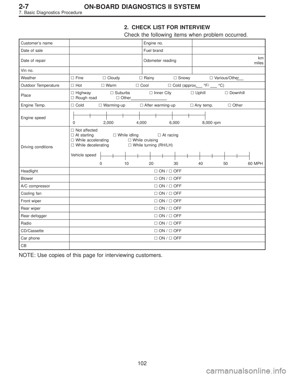
2. CHECK LIST FOR INTERVIEW
Check the following items when problem occurred.
Customer’s name Engine no.
Date of sale Fuel brand
Date of repair Odometer readingkm
miles
Vin no.
Weather�Fine�Cloudy�Rainy�Snowy�Various/Other
Outdoor Temperature�Hot�Warm�Cool�Cold (approx.°F/°C)
Place�Highway�Suburbs�Inner City�Uphill�Downhill
�Rough road�Other
Engine Temp.�Cold�Warming-up�After warming-up�Any temp.�Other
Engine speed
0 2,000 4,000 6,000 8,000 rpm
Driving conditions�Not affected
�At starting�While idling�At racing
�While accelerating�While cruising
�While decelerating�While turning (RH/LH)
Vehicle speed
0 10203040 5060MPH
Headlight�ON /�OFF
Blower�ON /�OFF
A/C compressor�ON /�OFF
Cooling fan�ON /�OFF
Front wiper�ON /�OFF
Rear wiper�ON /�OFF
Rear defogger�ON /�OFF
Radio�ON /�OFF
CD/Cassette�ON /�OFF
Car phone�ON /�OFF
CB
NOTE: Use copies of this page for interviewing customers.
102
2-7ON-BOARD DIAGNOSTICS II SYSTEM
7. Basic Diagnostics Procedure
Page 1309 of 2248
 Other warning lights or indicators turn on.�Ye s /�No
��
1Low fuel warning light
��
2Charge indicator light
��
3AT diagnosti")
Check the following items about the vehicle’s state when
MIL turns on.
a) Other warning lights or indicators turn on.�Ye s /�No
��
1Low fuel warning light
��
2Charge indicator light
��
3AT diagnostics indicator light
��
4ABS warning light
��
5TCS warning light
��
6Engine oil pressure warning light
b) Fuel level
�Lack of gasoline:�Ye s /�No
�Indicator position of fuel gauge:
c) Intentional connecting or disconnecting of harness connectors or spark plug cords:�Ye s /�No
�What:
d) Intentional connecting or disconnecting of hoses:�Ye s /�No
�What:
e) Installing of parts other than genuine parts�Ye s /�No
�What:
�Where:
f) Occurrence of noise�Ye s /�No
�From where:
�What kind:
g) Occurrence of smell�Ye s /�No
�From where:
�What kind:
h) Intrusion of water into engine compartment or passenger compartment�Ye s /�No
i) Troubles occurred
��
1Engine does not start.
��
2Engine stalls during idling.
��
3Engine stalls while driving.
��
4Engine speed decreases.
��
5Engine speed does not decrease.
��
6Rough idling
��
7Poor acceleration
��
8Back fire
��
9After fire
��
10No shift
��
11Excessive shift shock
NOTE: Use copies of this page for interviewing customers.
103
2-7ON-BOARD DIAGNOSTICS II SYSTEM
7. Basic Diagnostics Procedure
Page 1310 of 2248
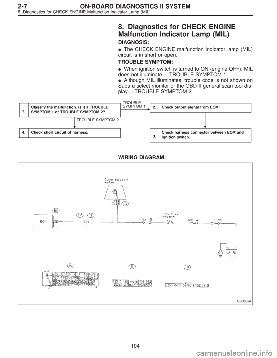
8. Diagnostics for CHECK ENGINE
Malfunction Indicator Lamp (MIL)
DIAGNOSIS:
�The CHECK ENGINE malfunction indicator lamp (MIL)
circuit is in short or open.
TROUBLE SYMPTOM:
�When ignition switch is turned to ON (engine OFF), MIL
does not illuminate.....TROUBLE SYMPTOM 1
�Although MIL illuminates, trouble code is not shown on
Subaru select monitor or the OBD-II general scan tool dis-
play.....TROUBLE SYMPTOM 2
1.Classify the malfunction. Is it a TROUBLE
SYMPTOM 1 or TROUBLE SYMPTOM 2?
TROUBLE SYMPTOM 2
�
TROUBLE
SYMPTOM 1
2.Check output signal from ECM.
4.Check short circuit of harness.3.Check harness connector between ECM and
ignition switch.
WIRING DIAGRAM:
OBD0094
��
104
2-7ON-BOARD DIAGNOSTICS II SYSTEM
8. Diagnostics for CHECK ENGINE Malfunction Indicator Lamp (MIL)
Page 1311 of 2248

1CLASSIFY THE MALFUNCTION. IS IT A
TROUBLE SYMPTOM 1 OR TROUBLE SYMP-
TOM 2?
If the malfunction shows TROUBLE SYMPTOM 1, go to
step 2.
If the malfunction shows TROUBLE SYMPTOM 2, go to
step 4.
OBD0095A
2
CHECK OUTPUT SIGNAL FROM ECM.
1) Turn ignition switch to ON.
2) Measure voltage between ECM and body.
: Connector & terminal
(B84) No. 31 — Body/1 V, or less
: Go to step 3.
:�If MIL comes on when shaking or pulling ECM
connector and harness, repair ECM connector.
�Check that ECM connector is correctly con-
nected. If the MIL does not come on even when
ECM connector is correctly connected, replace
the ECM.
OBD0096
3CHECK HARNESS CONNECTOR BETWEEN
ECM AND IGNITION SWITCH.
Check the following and repair if necessary.
�
1Check that fuse (No. 15) is not blown out.
NOTE:
If replaced fuse (No. 15) blows out easily, check the har-
ness for short circuit between fuse (No. 15) and combina-
tion meter.
�
2Check that harness from fuse to combination meter is
not open.
�
3Check that the MIL wiring is not open.
�
4Check that harness from combination meter to the ECM
is not open.
�
5Check that the connector (B37) is correctly connected
as the wiring diagram shows.
105
2-7ON-BOARD DIAGNOSTICS II SYSTEM
8. Diagnostics for CHECK ENGINE Malfunction Indicator Lamp (MIL)
Page 1312 of 2248
4
CHECK SHORT CIRCUIT OF HARNESS.
1) Turn ignition switch to OFF.
2) Disconnect connector from ECM.
3) Turn ignition switch to ON.
: Does the MIL come on?
: Repair short circuit of harness between ECM and
combination meter.
: Replace ECM.
106
2-7ON-BOARD DIAGNOSTICS II SYSTEM
8. Diagnostics for CHECK ENGINE Malfunction Indicator Lamp (MIL)
Page 1314 of 2248
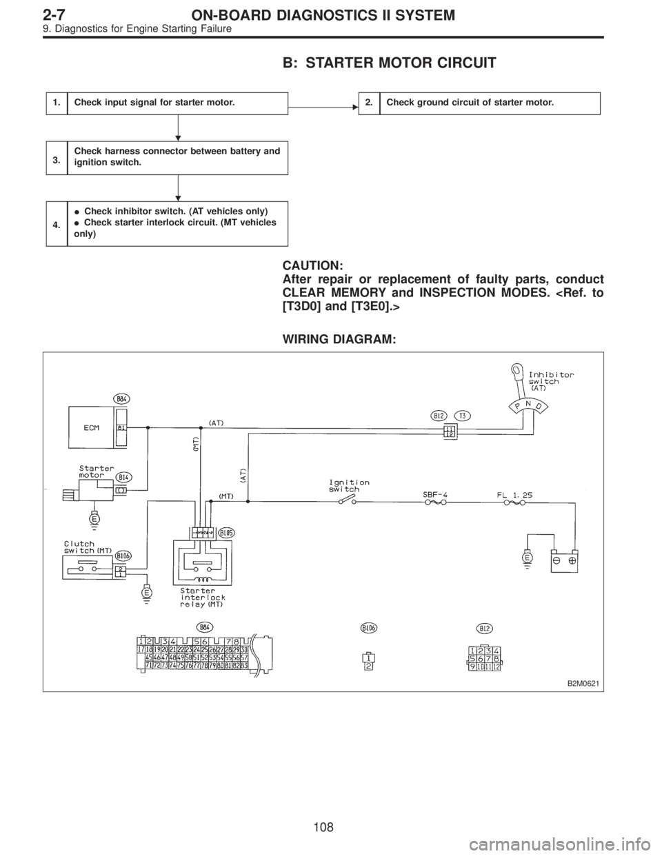
B: STARTER MOTOR CIRCUIT
1.Check input signal for starter motor.�2.Check ground circuit of starter motor.
3.Check harness connector between battery and
ignition switch.
4.
�Check inhibitor switch. (AT vehicles only)
�Check starter interlock circuit. (MT vehicles
only)
CAUTION:
After repair or replacement of faulty parts, conduct
CLEAR MEMORY and INSPECTION MODES.
[T3D0] and [T3E0].>
WIRING DIAGRAM:
B2M0621
�
�
108
2-7ON-BOARD DIAGNOSTICS II SYSTEM
9. Diagnostics for Engine Starting Failure
 Turn ignition switch to OFF.
2) Disconnect connector from ECM.
3) Turn ignition switch to ON.
: Does the MIL come on?
: Repair short circuit of harness between ECM")