Page 1214 of 2248
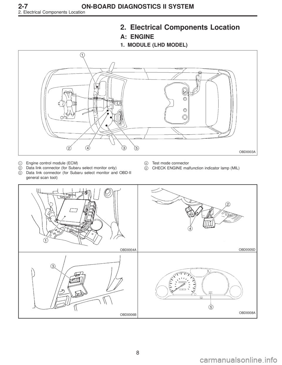
2. Electrical Components Location
A: ENGINE
1. MODULE (LHD MODEL)
OBD0003A
�1Engine control module (ECM)
�
2Data link connector (for Subaru select monitor only)
�
3Data link connector (for Subaru select monitor and OBD-II
general scan tool)�
4Test mode connector
�
5CHECK ENGINE malfunction indicator lamp (MIL)
OBD0004AOBD0005D
OBD0006BOBD0008A
8
2-7ON-BOARD DIAGNOSTICS II SYSTEM
2. Electrical Components Location
Page 1215 of 2248
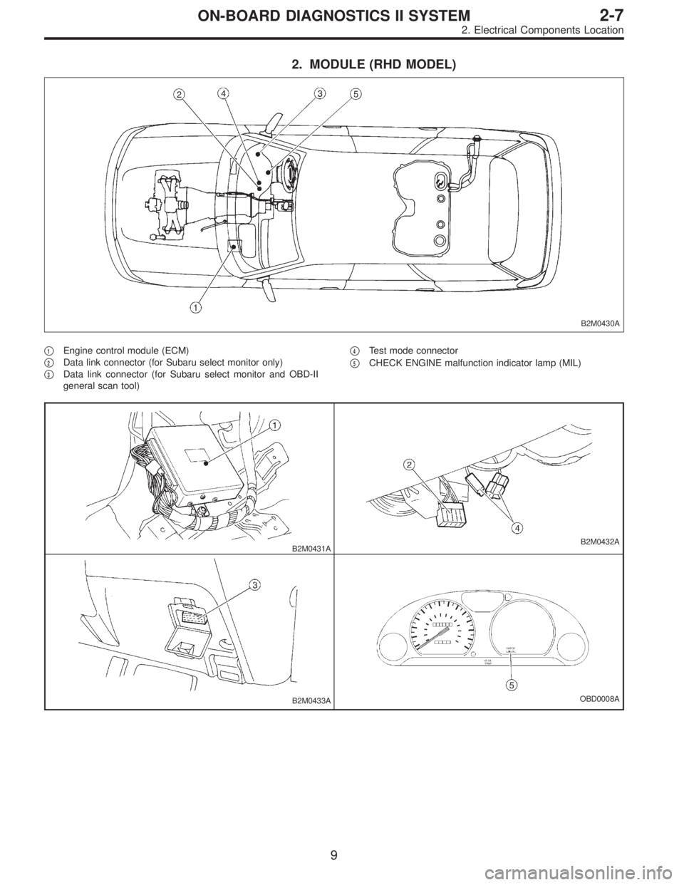
2. MODULE (RHD MODEL)
B2M0430A
�1Engine control module (ECM)
�
2Data link connector (for Subaru select monitor only)
�
3Data link connector (for Subaru select monitor and OBD-II
general scan tool)�
4Test mode connector
�
5CHECK ENGINE malfunction indicator lamp (MIL)
B2M0431AB2M0432A
B2M0433AOBD0008A
9
2-7ON-BOARD DIAGNOSTICS II SYSTEM
2. Electrical Components Location
Page 1233 of 2248
OBD0008C
3. Diagnosis System
A: MALFUNCTION INDICATOR LAMP (MIL)
1. ACTIVATION OF MALFUNCTION INDICATOR LAMP
(MIL)
1) When ignition switch is turned to ON (engine off), the
CHECK ENGINE malfunction indicator lamp (MIL) in the
combination meter illuminates.
NOTE:
If the MIL does not illuminate, perform diagnostics of the
CHECK ENGINE light circuit or the combination meter cir-
cuit.
function Indicator Lamp (MIL) [T800]”.>
OBD0053A
2) After starting the engine, the MIL goes out. If it does not,
either the engine or the emission control system is mal-
functioning.
OBD0054A
3) If the diagnosis system senses a misfire which could
damage the catalyzer, the MIL will blink at a cycle of 1 Hz.
OBD0055A
4) When ignition switch is turned to ON (engine off) or to
“START” with the test mode connector connected, the MIL
blinks at a cycle of 3 Hz.
27
2-7ON-BOARD DIAGNOSTICS II SYSTEM
3. Diagnosis System
Page 1235 of 2248

3. READ DATA LIST
�MODE $01
—Current powertrain diagnostic data—
Refers to data denoting the current operating condition of
analog input/output, digital input/output and/or the power-
train system.
A list of the support data and PID (Parameter Identification)
codes are shown in the following table.
PID DataUnit of measure
01 Number of emission-related powertrain trouble codes and MIL status ON/OFF
03 Fuel system control status—
04 Calculated engine load value%
05 Engine coolant temperature°C
06 Short term fuel trim%
07 Long term fuel trim%
0B Intake manifold absolute pressurekPa
0C Engine revolutionrpm
0D Vehicle speedkm/h
0E Ignition timing advance°
10 Air flow rate from mass air flow sensor g/sec
11 Throttle valve opening angle%
13 Check whether oxygen sensor is installed.—
14 Oxygen sensor output voltage and short term fuel trim associated with oxygen sensor—bank 1 V and %
15 Oxygen sensor output voltage and short term fuel trim associated with oxygen sensor—bank 2 V and %
1C On-board diagnosis system—
NOTE:
Refer to OBD-II general scan tool manufacturer’s instruc-
tion manual to access generic OBD-II PIDs (MODE $01).
29
2-7ON-BOARD DIAGNOSTICS II SYSTEM
3. Diagnosis System
Page 1242 of 2248
Function mode Contents Abbreviation Unit of measure
F50 Load data (Freeze frame data) LOAD�F %
F51 Engine coolant temperature signal (Freeze frame data) TW�F °C
F52 Short term fuel trim (Freeze frame data) ALPH�F %
F53 Long term fuel trim (Freeze frame data) KBLR�F %
F54Intake manifold absolute pressure signal (Freeze frame
data) MANI�F kPa
F55 Engine speed signal (Freeze frame data) EREV�F rpm
F56 Vehicle speed signal (Freeze frame data) VSP�F km/h
FA 0 O N)OFF signal — —
FA 1 O N)OFF signal — —
FA 2 O N)OFF signal — —
FA 3 O N)OFF signal — —
FA 4 O N)OFF signal — —
FB0 Diagnostic trouble code (DTC) INSPECT —
FB1 Diagnostic trouble code (DTC) OBD —
FC0 Clear memory — —
NOTE:
1) Subaru select monitor is also available for monitoring
information other than that used for check and repair of the
vehicle.
2) The maximum values shown for F33, F34, F35 and F36
do not indicate the actual cylinder misfire rate.
36
2-7ON-BOARD DIAGNOSTICS II SYSTEM
3. Diagnosis System
Page 1258 of 2248
G3M0723
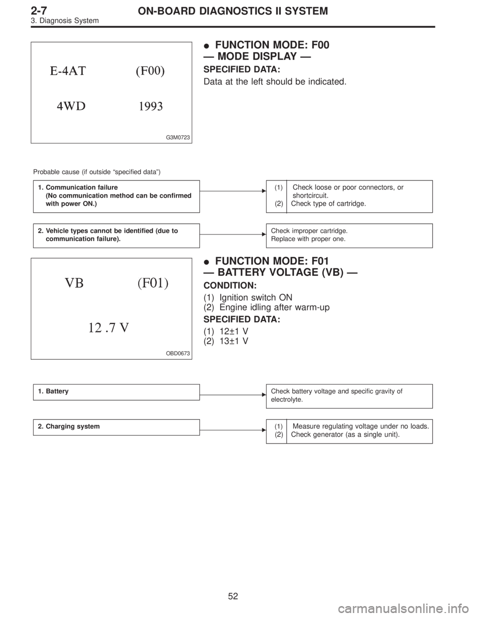
�FUNCTION MODE: F00
—MODE DISPLAY—
SPECIFIED DATA:
Data at the left should be indicated.
Probable cause (if outside“specified data”)
1. Communication failure
(No communication method can be confirmed
with power ON.)
�(1)Check loose or poor connectors, or
shortcircuit.
(2) Check type of cartridge.
2. Vehicle types cannot be identified (due to
communication failure).�Check improper cartridge.
Replace with proper one.
OBD0673
�FUNCTION MODE: F01
—BATTERY VOLTAGE (VB)—
CONDITION:
(1) Ignition switch ON
(2) Engine idling after warm-up
SPECIFIED DATA:
(1) 12±1 V
(2) 13±1 V
1. Battery�Check battery voltage and specific gravity of
electrolyte.
2. Charging system�(1)Measure regulating voltage under no loads.
(2) Check generator (as a single unit).
52
2-7ON-BOARD DIAGNOSTICS II SYSTEM
3. Diagnosis System
Page 1268 of 2248
 Connect test mode connector at the lower side of the
inst")
OBD0005B
3. OBD-II GENERAL SCAN TOOL
After performing diagnostics and clearing the memory,
check for any remaining unresolved trouble data:
1) Connect test mode connector at the lower side of the
instrument panel (on the driver’s side), to the side of the
center console box.
OBD0006C
2) Open the cover and connect the OBD-II general scan
tool to its data link connector in the lower portion of the
instrument panel (on the driver’s side), to the lower cover.
CAUTION:
Do not connect the scan tools except for Subaru select
monitor and OBD-II general scan tool.
3) Start the engine.
NOTE:
�Ensure the selector lever is placed in the“P”position
before starting. (AT vehicles)
�Depress clutch pedal when starting the engine. (MT
vehicles)
4) Using the selector lever or shift lever, turn the“P”posi-
tion switch and the“N”position switch to ON.
5) Depress the brake pedal to turn the brake switch ON.
(AT vehicles)
6) Keep engine speed in the 2,500—3,000 rpm range for
40 seconds.
NOTE:
On models without tachometer, use the Subaru select
monitor or tachometer (Secondary pickup type).
7) Place the selector lever or shift lever in the“D”position
(AT vehicles) or“1st”gear (MT vehicles) and drive the
vehicle at 5 to 10 km/h (3 to 6 MPH).
NOTE:
�On AWD vehicles, release the parking brake.
�The speed difference between front and rear wheels
may light either the ABS or the ABS/TCS warning light, but
this indicates no malfunctions. When engine control diag-
nosis is finished, perform the ABS or the ABS/TCS memory
clearance procedure of self-diagnosis system.
4-4a [T6C2] or 4-4b [T6C2] or [T9K0].>
62
2-7ON-BOARD DIAGNOSTICS II SYSTEM
3. Diagnosis System
Page 1272 of 2248
 Before disconnecting t")
�When mounting a large power type radio, pay spe-
cial attention to the three items above mentioned.
�Incorrect installation of the radio may affect the
operation of the ECM.
8) Before disconnecting the fuel hose, disconnect the fuel
pump connector and crank the engine for more than five
seconds to release pressure in the fuel system. If engine
starts during this operation, run it until it stops.
9) Problems in the electronic-controlled automatic trans-
mission may be caused by failure of the engine, the elec-
tronic control system, the transmission proper, or by a com-
bination of these. These three causes must be distin-
guished clearly when performing diagnostics.
10) Diagnostics should be conducted by rotating with
simple, easy operations and proceeding to complicated,
difficult operations. The most important thing in diagnostics
is to understand the customer’s complaint, and distinguish
between the three causes.
11) In AT vehicles, do not continue the stall for more than
five seconds at a time (from closed throttle, fully open
throttle to stall engine speed).
12) On ABS or ABS/TCS vehicle, when performing driving
test in jacked-up or lifted-up position, sometimes the warn-
ing light may be lit, but this is not a malfunction of the sys-
tem. The reason for this is the speed difference between
the front and rear wheels. After diagnosis of engine control
system, perform the ABS or ABS/TCS memory clearance
procedure of self-diagnosis system.
4-4b [T6C2] or [T9K0].>
C: PRE-INSPECTION
Before performing diagnostics, check the following items
which might affect engine problems:
1. POWER SUPPLY
1) Measure battery voltage and specific gravity of electro-
lyte.
Standard voltage: 12 V
Specific gravity: Above 1.260
2) Check the condition of the main and other fuses, and
harnesses and connectors. Also check for proper ground-
ing.
OBD0091A
2. ENGINE GROUNDING
Make sure the engine grounding terminal is properly con-
nected to the engine.
66
2-7ON-BOARD DIAGNOSTICS II SYSTEM
4. Cautions

1. ACTIVATION OF MALFUNCTION INDICATOR LAMP
(MIL)
1) When ignition switch is turned to ON (engine off), the
CHECK ENGINE malfunction in")
 LOAD�F %
F51 Engine coolant temperature signal (Freeze frame data) TW�F °C
F52 Short term fuel trim (Freeze frame")