1995 NISSAN ALMERA N15 fuel
[x] Cancel search: fuelPage 793 of 1701
TROUBLEDIAGNOSES -General Description
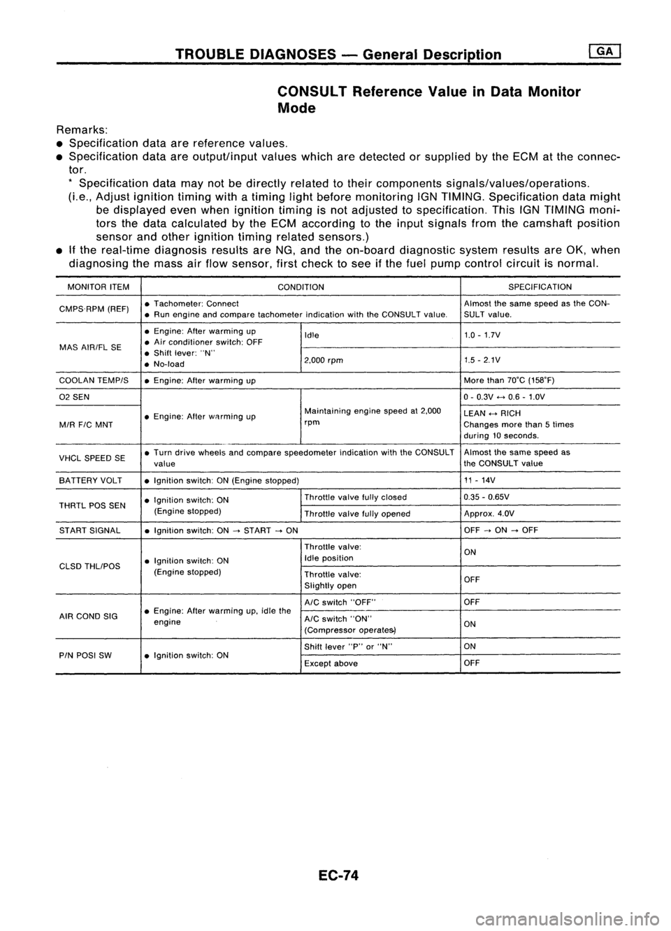
CONSULT ReferenceValueinData Monitor
Mode
Remarks:
• Specification dataarereference values.
• Specification dataareoutput/input valueswhicharedetected orsupplied bythe ECM atthe connec-
tor.
*
Specification datamaynotbedirectly relatedtotheir components signals/values/operations.
(Le., Adjust ignition timingwithatiming lightbefore monitoring IGNTIMING. Specification datamight
be displayed evenwhen ignition timingisnot adjusted tospecification. ThisIGNTIMING moni-
tors thedata calculated bythe ECM according tothe input signals fromthecamshaft position
sensor andother ignition timingrelated sensors.)
• Ifthe real-time diagnosis resultsareNG, and theon-board diagnostic systemresultsareOK, when
diagnosing themass airflow sensor, firstcheck tosee ifthe fuel pump control circuitisnormal.
MONITOR ITEM
CONDITION SPEC
IFICA TION
CMPS.RPM (REF)•
Tachometer: Connect Almostthesame speed asthe CON-
• Run engine andcompare tachometer indicationwiththeCONSULT value.SULT value.
• Engine: Afterwarming up
Idle 1.0
-1.7V
MAS AIRIFL SE •
Air conditioner switch:OFF
• Shift lever: "N"
• No-load 2,000
rpm 1.5
-2.1V
COOLAN TEMPIS •Engine: Afterwarming up More
than70°C (158°F)
02 SEN 0-
0.3V
<-+
0.6 -1.0V
• Engine: Afterwflrming up Maintaining
enginespeedat2,000
LEAN
<-+
RICH
MIR
FIC
MNT rpm
Changesmorethan5times
during 10seconds .
VHCL SPEED SE•
Turn drive wheels andcompare speedometer indicationwiththeCONSULT Almost
thesame speed as
value the
CONSULT value
SA TTERY VOLT •Ignition switch:ON(Engine stopped) 11
-14V
• Ignition switch:ON Throttle
valvefullyclosed 0.35
-0.65V
THRTL POSSEN
(Enginestopped)
Throttlevalvefullyopened Approx.
4.0V
ST ART SIGNAL •Ignition switch:ON
-->
START
-->
ON OFF
-->
ON
-->
OFF
Throttle valve:
ON
• Ignition switch:ON Idle
position
CLSD THLIPOS
(Enginestopped)
Throttlevalve:
OFF
Slightly open
AIC
switch "OFF" OFF
AIR COND SIG •
Engine: Afterwarming up,idle the
engine
AIC
switch "ON"
ON
(Compressor operate&)
Shift lever "P"or"N" ON
PIN POSI SW •Ignition switch:ON
Exceptabove OFF
EC-74
Page 794 of 1701
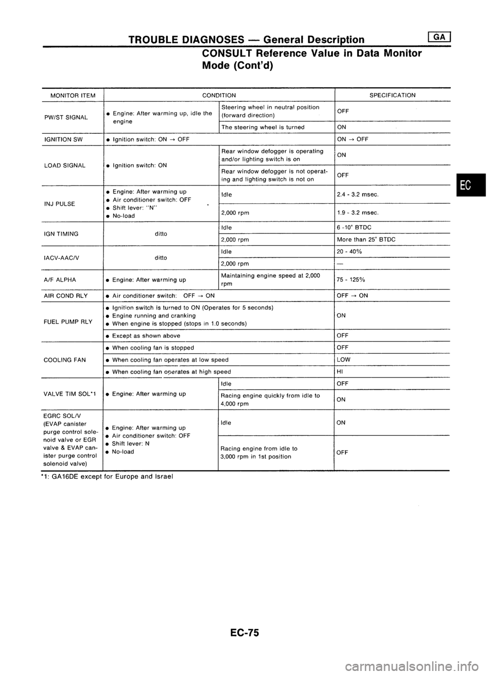
TROUBLEDIAGNOSES -General Description @KJ
CONSULT Reference ValueinData Monitor
Mode (Cont'd)
MONITOR ITEM CONDITION
SPECIFICATION
Steering wheelinneutral position
OFF
PW/ST SIGNAL •
Engine: Afterwarming up.idle the
(forward direction)
engine Thesteering wheelisturned ON
IGNITION SW •
Ignition switch:ON
-->
OFF ON
-->
OFF
Rear window defogger isoperating
ON
and/or lighting switchison
LOAD SIGNAL •
Ignition switch:ON
Rearwindow defogger isnot operat-
OFF
ing and lighting switchisnot on
• Engine: Afterwarming up
Idle 2.4
-3.2 msec.
INJ PULSE •
Air conditioner switch:OFF
• Shift lever: "N"
.
• No-load 2.000
rpm 1.9
-3.2 msec.
Idle 6
_10' BTDC
IGN TIMING ditto
2.000rpm More
than25'BTDC
Idle 20-40%
IACV-AACIV ditto
2.000rpm
-
A/F ALPHA •
Engine: Afterwarming up Maintaining
enginespeedat2.000
75-125%
rpm
AIR COND RLY •
Air conditioner switch:OFF
-->
ON OFF
-->
ON
• Ignition switchisturned toON (Operates for5seconds)
• Engine running andcranking ON
FUEL PUMP RLY
•When engine isstopped (stopsin1.0 seconds)
• Except asshown above OFF
• When cooling fanisstopped OFF
COOLING FAN •
When cooling fanoperates atlow speed LOW
• When cooling fano!Jerates athigh speed HI
Idle OFF
VALVE TIMSOL'1 •Engine: Afterwarming up
Racingenginequickly fromidleto
4.000 rpm ON
EGRC SOLIV
(EVAP canister Idle
ON
purge control sole-•
Engine: Afterwarming up
• Air conditioner switch:OFF
noid valve orEGR
•Shift lever: N
valve
&
EVAP can-
•No-load Racing
enginefromidleto
ister purge control
3.000rpmin1st position OFF
solenoid valve)
*1: GA16DE exceptforEurope andIsrael
EC-75
•
Page 798 of 1701
![NISSAN ALMERA N15 1995 Service Manual TROUBLEDIAGNOSES -General Description @K]
ECM Terminals andReference Value(Conl'd)
ECM INSPECTION TABLE-GA16DE forAustralia
Specification dataarereference valuesandaremeasured betweeneachterminal NISSAN ALMERA N15 1995 Service Manual TROUBLEDIAGNOSES -General Description @K]
ECM Terminals andReference Value(Conl'd)
ECM INSPECTION TABLE-GA16DE forAustralia
Specification dataarereference valuesandaremeasured betweeneachterminal](/manual-img/5/57349/w960_57349-797.png)
TROUBLEDIAGNOSES -General Description @K]
ECM Terminals andReference Value(Conl'd)
ECM INSPECTION TABLE-GA16DE forAustralia
Specification dataarereference valuesandaremeasured betweeneachterminal and
@
(ECCS ground).
TER- WIRE
MINAL ITEM
CONDITION DATA
NO. COLOR
[Efl9ineisrunning.
I
0.3-0.6V
L Idle speed
1
WIB
Ignitionsignal
I
Engine isrunning.
I
L Engine speedis2,000 rpm. Approximately
0.9V
2
GYIR
Ignition
check IEngine
isrunning.
I
Approximately12V
L Idle speed
3 LIB Tachometer [Engine
isrunning.
I
Approximately0.9V
L Idle speed
IEngine isrunning.
I
Ilgnition switch"OFF'.'
0-1V
4
WIG
ECCS
relay(Self-shut- L
For afew seconds afterturning ignition
off) switch
"OFF"
Ilgnition switch"OFF"
I
BATTERYVOLTAGE
L Afew seconds passedafterturning ignition
(11-14V)
switch "OFF"
Ilgnition switch"ON"
I
L For 5seconds afterturning ignition switch
0.07-0.20V
"ON"
8
BIP Fuel
pump relay I
Engine isrunning.
I
Ilgnition switch"ON"
I
BATTERYVOLTAGE
L More than5seconds afterturning ignition
(11-14V)
switch "ON"
10
BIW
ECCSground IEngine
isrunning.
I
Engineground
L Idle speed
IEngine isrunning.
I
BATTERYVOLTAGE
Cooling fanrelay ~Cooling fanisnot operating.
(11-14V).
13 LG
(Highspeed: For
AIT
Cooling
fanisoperating atlow speed.
models)
I
Engine isrunning.
I
L Cooling fanisoperating athigh speed. Approximately
OV
IEngine isrunning.
I
BATTERYVOLTAGE
Cooling fanrelay L
Cooling fanisnot operating. (11-14V)
14 LGIR
(Lowspeed)
I
Engine isrunning.
I
L_
Cooling fanisoperating. 0.07
-0.30V
I
Engine isrunning.
I
L Both
AIC
switch andblower switchare 0.08
-0.2V
15
Y
Air
conditioner relay "ON".
IEngine isrunning.
I
BATTERYVOLTAGE
LAIC switchis"OFF". (11
-14V)
EC-79
•
Page 805 of 1701
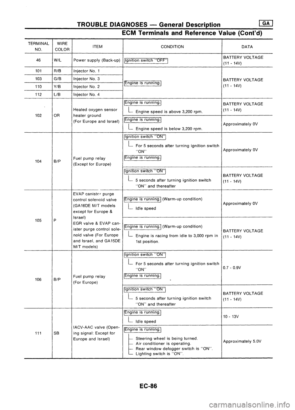
TROUBLEDIAGNOSES -General Description
mJ
ECM Terminals andReference Value(Cont'd)
TERMINAL WIRE
NO. COLOR ITEM
CONDITION DATA
46 WIL Powersupply (Back-up)
Ilgnitionswitch"OFF'" BA
TTERY VOLTAGE
(11 -14V)
101 RIB InjectorNo.1
103
GIB
InjectorNo.3
BATTERYVOLTAGE
110 Y/B InjectorNO.2 IEngine
isrunning./
(11-14V)
112 LIB Injector
NO.4
IEngineisrunning.1
BATTERY VOLTAGE
Heated oxygen sensor
L
Engine speedisabove 3,200rpm. (11
-14V)
102 OR heaterground
(For Europe andIsrael) IEngine
isrunning.1
ApproximatelyOV
L
Engine speedisbelow 3,200rpm.
jlgnition switch"ON"I
L
For 5seconds afterturning ignition switch
"ON" Approximately
OV
104 B/P Fuel
pump relay /Engine
isrunning.1
(Except forEurope)
Ilgnitionswitch"ON"I
BATTERYVOLTAGE
L
5seconds afterturning ignition switch
(11-14V)
"ON" andthereafter
EVAP canister purge
control solenoid valveIEngine
isrunning.1 (Warm-up condition)
(GA16DE
MIT
models
L
Idle speed Approximately
OV
except forEurope
&
105 P Israel)
EGR valve
&
EVAP can-
ister purge control sole-IEngine
isrunning.1 (Warm-up condition)
BATTERYVOLTAGE
noid valve (ForEurope
L
Engine isracing fromidleto3,000 rpmin
(11-14V)
and Israel, andGA15DE
1st position.
MIT
models)
jlgnitionswitch"ON"I
L
For 5seconds afterturning ignition switch
"ON" 0.7
-0.9V
106 SIP Fuel
pump relay IEngine
isrunning.1
(For Europe)
-
Ilgnition switch"ON"I
BATTERYVOLTAGE
L
5seconds afterturning ignition switch
(11-14V)
"ON" andthereafter
IEngine isrunning.1
10-13V
L
Idle speed
IACV-AAC valve(Open-
IEngineisrunning.1
111 5B ingsignal: Exceptfor
Europe andIsrael)
l
51.."" wheel
t,
be'" I,med
Approximately5.0V
Air conditioner isoperating.
Rear window defogger switchis"ON".
Lighting switchis"ON".
EC-86
Page 813 of 1701
TROUBLEDIAGNOSIS FORDTC11
Light emitting
diode
Wave
forming circuit
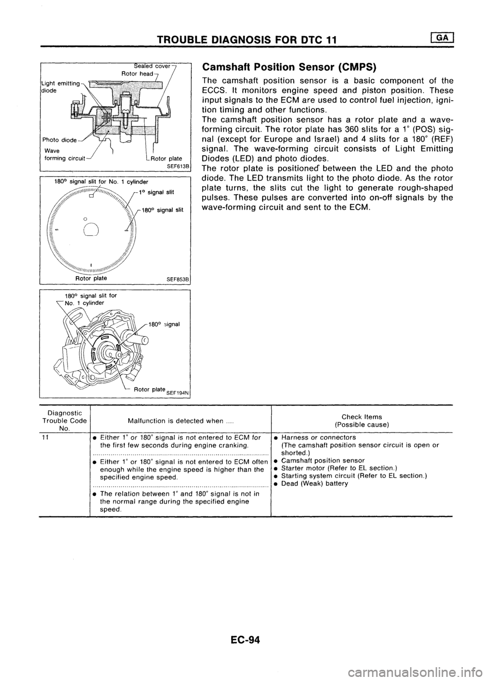
Camshaft
PositionSensor(CMPS)
The camshaft positionsensorisabasic component ofthe
EGGS. Itmonitors enginespeedandpiston position. These
input signals tothe EGM areused tocontrol fuelinjection, igni-
tion timing andother functions.
The camshaft positionsensorhasarotor plate andawave-
forming circuit.Therotor plate has360slits fora1
0
(paS) sig-
nal (except forEurope andIsrael) and4slits fora180
0
(REF)
signal. Thewave-forming circuitconsists ofLight Emitting
Diodes (LED)andphoto diodes.
The rotor plate ispositioned' betweentheLED andthephoto
diode. TheLED transmits lighttothe photo diode. Asthe rotor
plate turns, theslits cutthe light togenerate rough-shaped
pulses. Thesepulses areconverted intoon-off signals bythe
wave-forming circuitandsent tothe EGM.
SEF653B
180
0
signal
Diagnostic
Trouble Code
No.
11
Malfunction
isdetected when....
• Either
l'
or 180' signal isnot entered toECM for
the first fewseconds duringengine cranking.
• Either
l'
or 180' signal isnot entered toECM often
enough whiletheengine speedishigher thanthe
specified enginespeed.
• The relation between
l'
and 180'signal isnot in
the normal rangeduring thespecified engine
speed.
EC-94
Check
Items
(Possible cause)
• Harness orconnectors
(The camshaft positionsensorcircuitisopen or
shorted.)
• Camshaft positionsensor
• Starter motor(Refer toEL section.)
• Starting systemcircuit(RefertoEL section.)
• Dead (Weak) battery
Page 847 of 1701
TROUBLEDIAGNOSIS FORNON-DETECTABLE ITEMS
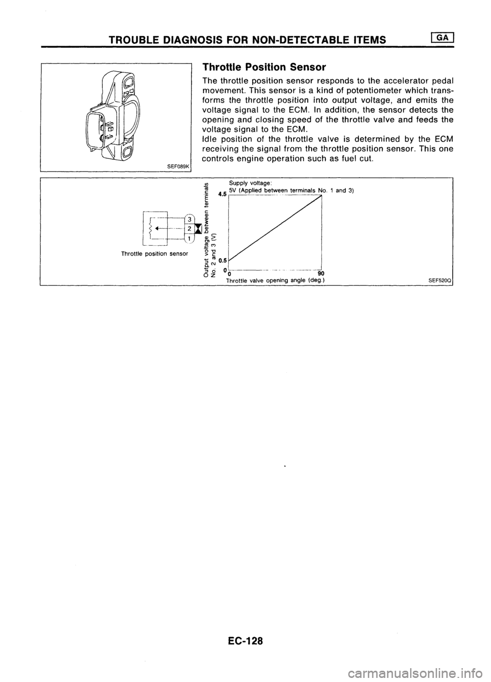
Throttle Position Sensor
The throttle position sensorresponds tothe accelerator pedal
movement. Thissensor isakind ofpotentiometer whichtrans-
forms thethrottle position intooutput voltage, andemits the
voltage signaltothe ECM. Inaddition, thesensor detects the
opening andclosing speedofthe throttle valveandfeeds the
voltage signaltothe ECM.
Idle position ofthe throttle valveisdetermined
by
the ECM
receiving thesignal fromthethrottle position sensor.Thisone
controls engineoperation suchasfuel cut.
SEF089K
CIl
Supplyvoltage:
r
-i.~h __
~3_
i
45
I
'V ,Appl.' b....
ffi
t~miMI,
No1,,'
31
~_ =r--=-tfr ~
I
l ~
1
N~
I
Throttle position sensor g
-g
'5 ::: 0.5
0-
'5
0 0----- -_.- --------_.
OZ 0 90
Throttle valveopening angle(deg_)
EC-128 SEF520Q
Page 862 of 1701
•
INSPECTION END
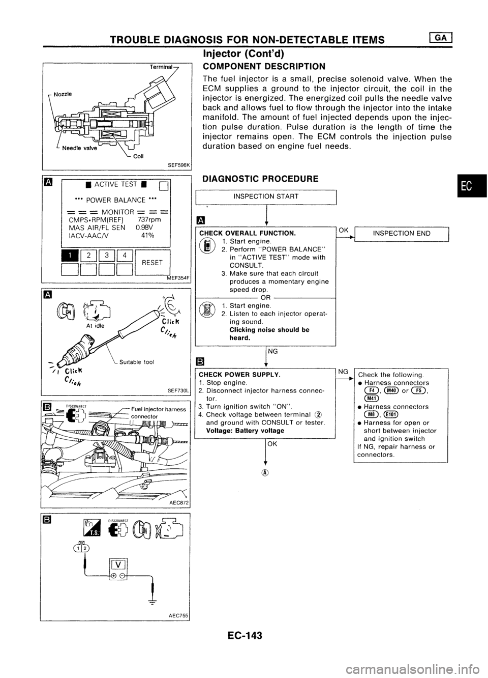
Check thefollowing.
• Harness connectors
@,@or@,
@
• Harness connectors
@,CillD
• Harness foropen or
short between injector
and ignition switch
If NG, repair harness or
connectors.
OK
NG
DIAGNOSTIC
PROCEDURE
INSPECTION START
CHECK OVERALL FUNCTION.
(F.I\
1.Start engine.
~ 2.Perform "POWER BALANCE"
in "ACTIVE TEST"modewith
CONSULT.
3. Make surethateach circuit
produces amomentary engine
speed drop.
OR
fff\
1.Start engine.
~ 2.Listen toeach injector operat-
ing sound.
Clicking noiseshould be
heard.
CHECK POWER SUPPLY.
1. Stop engine.
2. Disconnect injectorharness connec-
tor.
3. Turn ignition switch"ON".
4. Check voltage between terminal @
and ground withCONSULT ortester.
Voltage: Batteryvoltage
AEC872
SEF730L
/~~
Click
Ct.
'~.+
Fuel injector harness
connector
II
TROUBLE
DIAGNOSIS FORNON-DETECTABLE ITEMS
Injector (Cont'd)
COMPONENT DESCRIPTION
The fuel injector isasmall, precise solenoid valve.Whenthe
ECM supplies aground tothe injector circuit,thecoil
in
the
injector isenergized. Theenergized coilpulls theneedle valve
back andallows fueltoflow through theinjector intotheintake
manifold. Theamount offuel injected depends upontheinjec-
tion pulse duration. Pulseduration isthe length oftime the
injector remains open.TheECM controls theinjection pulse
duration basedonengine fuelneeds.
SEF596K
• ACTIVE TEST.
D
••• POWER BALANCE •••
= ==
MONITOR
=
==
CMPS.RPM(REF) 737rpm
MAS AIR/FL SEN098V
IACV-AAC/V 41%
110Q]Q]~
DDDDc:J
MEF354F
~7~
~ \)drJ
At idle
--
/ I
AEC755EC-143
Page 864 of 1701
TROUBLEDIAGNOSIS FORNON-DETECTABLE ITEMS
Fuel Pump
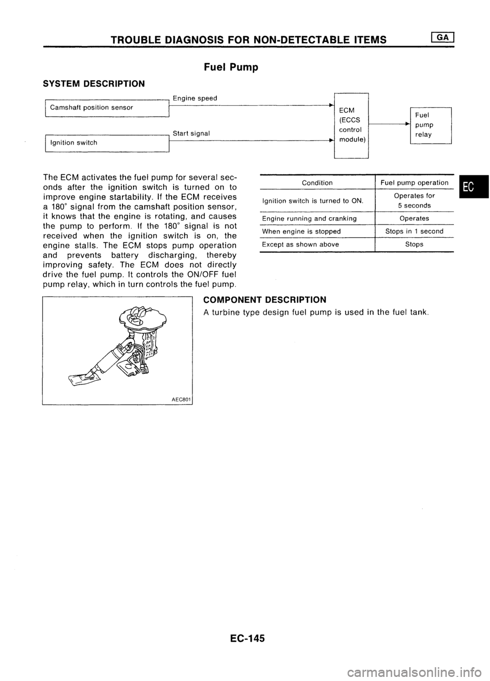
SYSTEM DESCRIPTION
Enginespeed
Camshaft positionsensor
Startsignal
Ignition switch
The ECM activates thefuel pump forseveral sec-
onds aftertheignition switchisturned onto
improve enginestartability. Ifthe ECM receives
a 180
0
signal fromthecamshaft positionsensor,
it knows thattheengine isrotating, andcauses
the pump toperform. Ifthe 180
0
signal isnot
received whentheignition switchison, the
engine stalls.TheECM stops pump operation
and prevents batterydischarging, thereby
improving safety.TheECM does notdirectly
drive thefuel pump. Itcontrols theON/OFF fuel
pump relay, which inturn controls thefuel pump.
ECM
(ECCS
control module)
Condition
Ignition switchisturned toON.
Engine running andcranking
When engine isstopped
Except asshown above Fuel
pump relay
Fuel pump operation
Operates for
5 seconds
Operates
Stops in1second
Stops
•
COMPONENT DESCRIPTION
A turbine typedesign fuelpump isused inthe fuel tank.
AEC801
EC-145