Page 614 of 1701
AUDIOANDANTENNA
Wiring Diagram -AUDIO -(Cont'd)
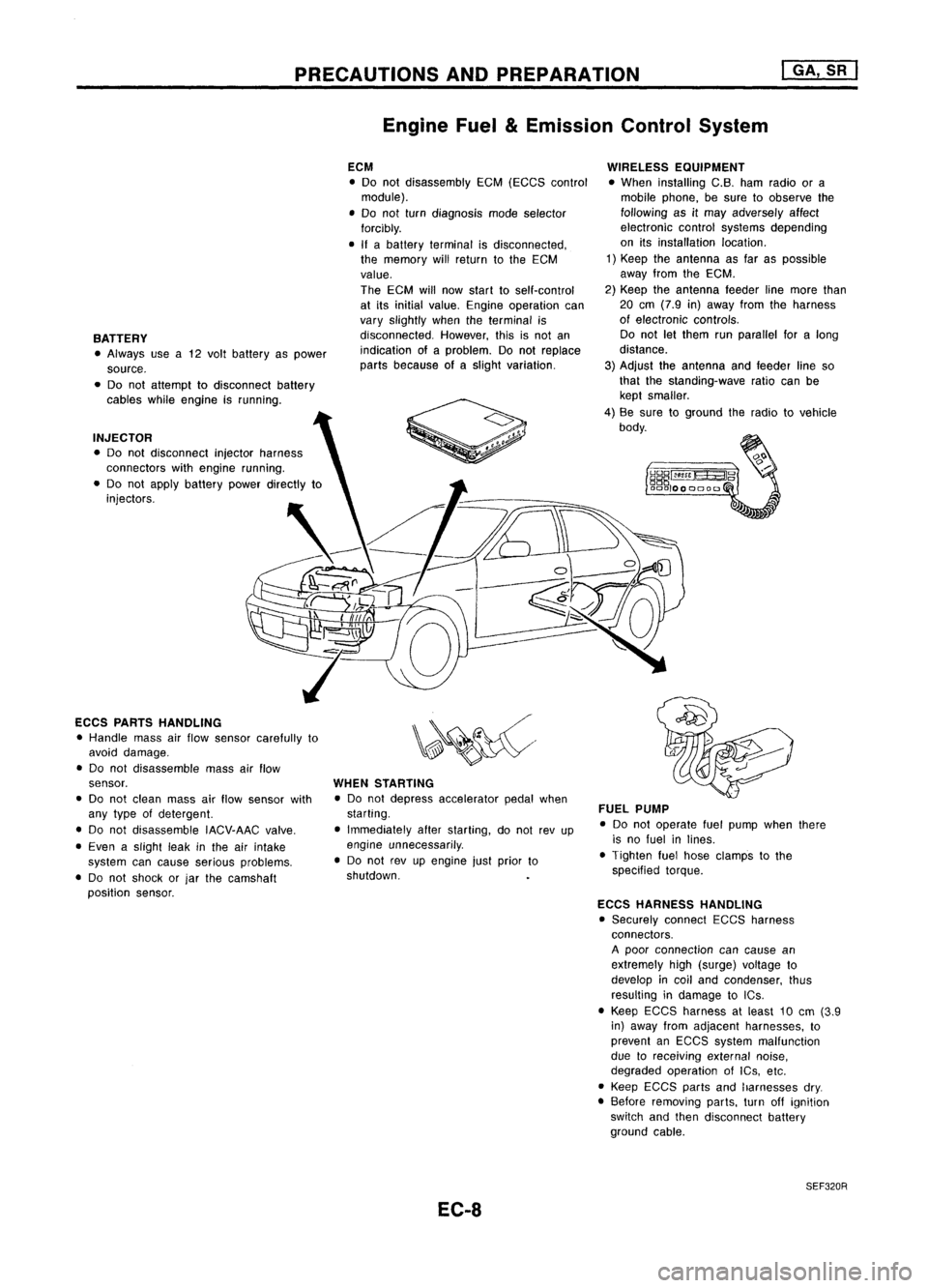
RHD MODELS EXCEPTFOREUROPE
EL-AUDIO-05
RADIOAND
CASSETTE
PLAYER
~ (fID)
RRSP
LH (-)
~
B/Y
-
ROD
ANTENNA
RRSP
LH (+)
~
LG
FUSE
Referto
BLOCK EL-POWER.
(JIB)
~
L
IffoD
ACC
RRSP
RH (-)
~
B/P
COMPACT
DISK
BACK DECK
UP ~
1
2•4
1 ~~
P P
I_t __ I
LIGHTING
SW
1
2
:1
RIG
t
FRSP
RH
(+)
I!4=Jl
BR
DIN
CORD
~~
~W
r---------------------~
I
I
~I
W :
I
Refer
tolast page
(Foldout page).
[Q] ~
@
C02)
@
[IIg]
BR.BR .BR .BR
HEL144
EL-242
Page 615 of 1701
AUDIOANDANTENNA
Antenna feeder
(RHO models) Radio
FuseCheck
Location ofAntenna
Antennafeeder
(LHO models)
Antenna RodReplacement
1. Loosen screwssecuring antennabase.
2. Pullout pipefrom antenna base.
Heating thepipe withadrier makes
it
easier.
EL-243 GEL020
•
Page 727 of 1701

PRECAUTIONSANDPREPARATION
Engine Fuel
&
Emission ControlSystem
I
GA, SR
I
BATTERY • Always usea12 volt battery aspower
source.
• Do not attempt todisconnect battery
cables whileengine isrunning.
INJECTOR • Do not disconnect injectorharness
connectors withengine running.
• Do not apply battery powerdirectly to
injectors.
ECCS PARTS HANDLING
• Handle massairflow sensor carefully to
avoid damage.
• Do not disassemble massairflow
sensor.
• Do not clean massairflow sensor with
any type ofdetergent.
• Do not disassemble IACV-AACvalve.
• Even aslight leakinthe airintake
system cancause serious problems.
• Do not shock orjar the camshaft
position sensor. ECM
• Do not disassembly EGM(EGGS control
module).
• Do not turn diagnosis modeselector
forcibly.
• Ifabattery terminal isdisconnected,
the memory willreturn tothe ECM
value.
The ECM willnow start toself-control
at its initial value. Engine operation can
vary slightly whentheterminal is
disconnected. However,thisisnot an
indication ofaproblem. Donot replace
parts because ofaslight variation.
WHEN STARTING
• Do not depress accelerator pedalwhen
starting.
• Immediately afterstarting, donot revup
engine unnecessarily .
• Do not revupengine justprior to
shutdown.
EC-8 WIRELESS
EQUIPMENT
• When installing C.B.hamradio ora
mobile phone, besure toobserve the
following asitmay adversely affect
electronic controlsystems depending
on itsinstallation location.
1) Keep theantenna asfar aspossible
away fromtheEGM.
2) Keep theantenna feederlinemore than
20 em (7.9 in)away fromtheharness
of electronic controls.
Do not letthem runparallel foralong
distance.
3) Adjust theantenna andfeeder lineso
that thestanding-wave ratiocanbe
kept smaller.
4) Be sure toground theradio tovehicle
body.
FUEL PUMP
• Do not operate fuelpump whenthere
is no fuel inlines.
• Tighten fuelhose clamps tothe
specified torque.
ECCS HARNESS HANDLING
• Securely connectEGGSharness
connectors.
A poor connection cancause an
extremely high(surge) voltage to
develop incoil and condenser, thus
resulting indamage toICs .
• Keep ECGS harness atleast 10em (3.9
in) away fromadjacent harnesses, to
prevent anEGGS system malfunction
due toreceiving externalnoise,
degraded operation ofIGs, etc.
• Keep EGCS partsandharnesses dry.
• Before removing parts,turnoffignition
switch andthen disconnect battery
ground cable.
SEF320R
Page 1372 of 1701

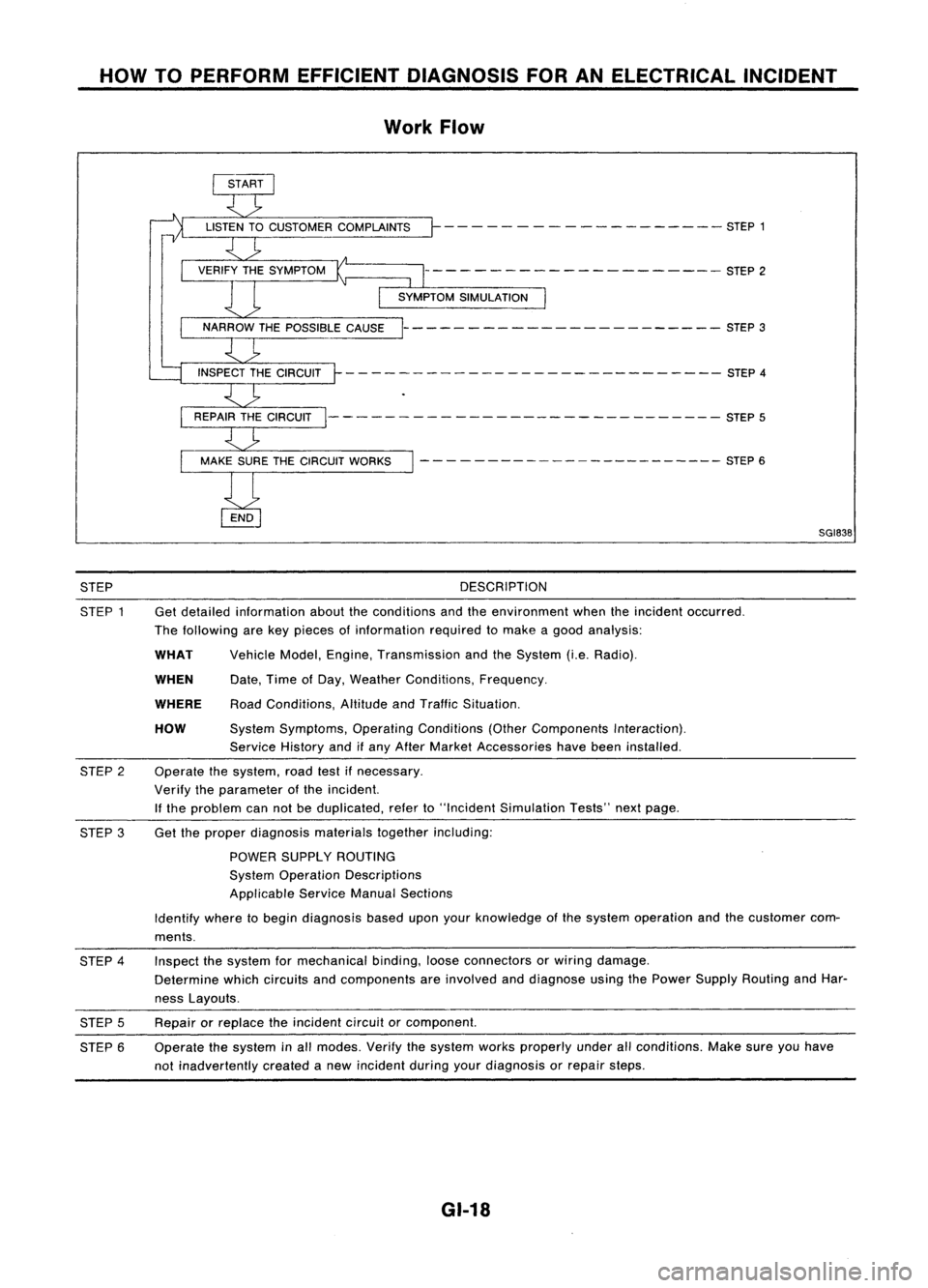
HOWTOPERFORM EFFICIENT DIAGNOSIS FORANELECTRICAL INCIDENT
Work Flow
- - - -- - -- ------ -- - -- STEP 1
--------------------- STEP2
----------------------- STEP3
- - -- ---- - --- - -- --- --- - - --- -- STEP 4
--------- -------------------- STEP5
- - - - ---- -- -- -- -- -- --- --- STEP 6
SGI838
STEP
STEP 1 DESCRIPTION
Get detailed information abouttheconditions andtheenvironment whentheincident occurred.
The following arekey pieces ofinformation requiredtomake agood analysis:
HOW
WHEN
WHAT
WHERE
Vehicle
Model,Engine, Transmission andtheSystem (i.e.Radio).
Date, TimeofDay, Weather Conditions, Frequency.
Road Conditions, AltitudeandTraffic Situation.
System Symptoms, OperatingConditions (OtherComponents Interaction).
Service Historyandifany After Market Accessories havebeen installed.
Operate thesystem, roadtestifnecessary.
Verify theparameter ofthe incident.
If the problem cannotbeduplicated, referto"Incident Simulation Tests"nextpage.
STEP
2
STEP 3Get
theproper diagnosis materialstogetherincluding:
POWER SUPPLY ROUTING
System Operation Descriptions
Applicable ServiceManualSections
Identify wheretobegin diagnosis baseduponyourknowledge ofthe system operation andthecustomer com-
ments.
STEP 4
STEP 5
STEP 6 Inspect
thesystem formechanical binding,looseconnectors orwiring damage.
Determine whichcircuits andcomponents areinvolved anddiagnose usingthePower Supply Routing andHar-
ness Layouts.
Repair orreplace theincident circuitorcomponent.
Operate thesystem inall modes. Verifythesystem worksproperly underallconditions. Makesureyouhave
not inadvertently createdanew incident duringyourdiagnosis orrepair steps.
GI-18
Page 1376 of 1701

HOWTOPERFORM EFFICIENT DIAGNOSIS FORANELECTRICAL INCIDENT
Incident Simulation Tests(Cont'd)
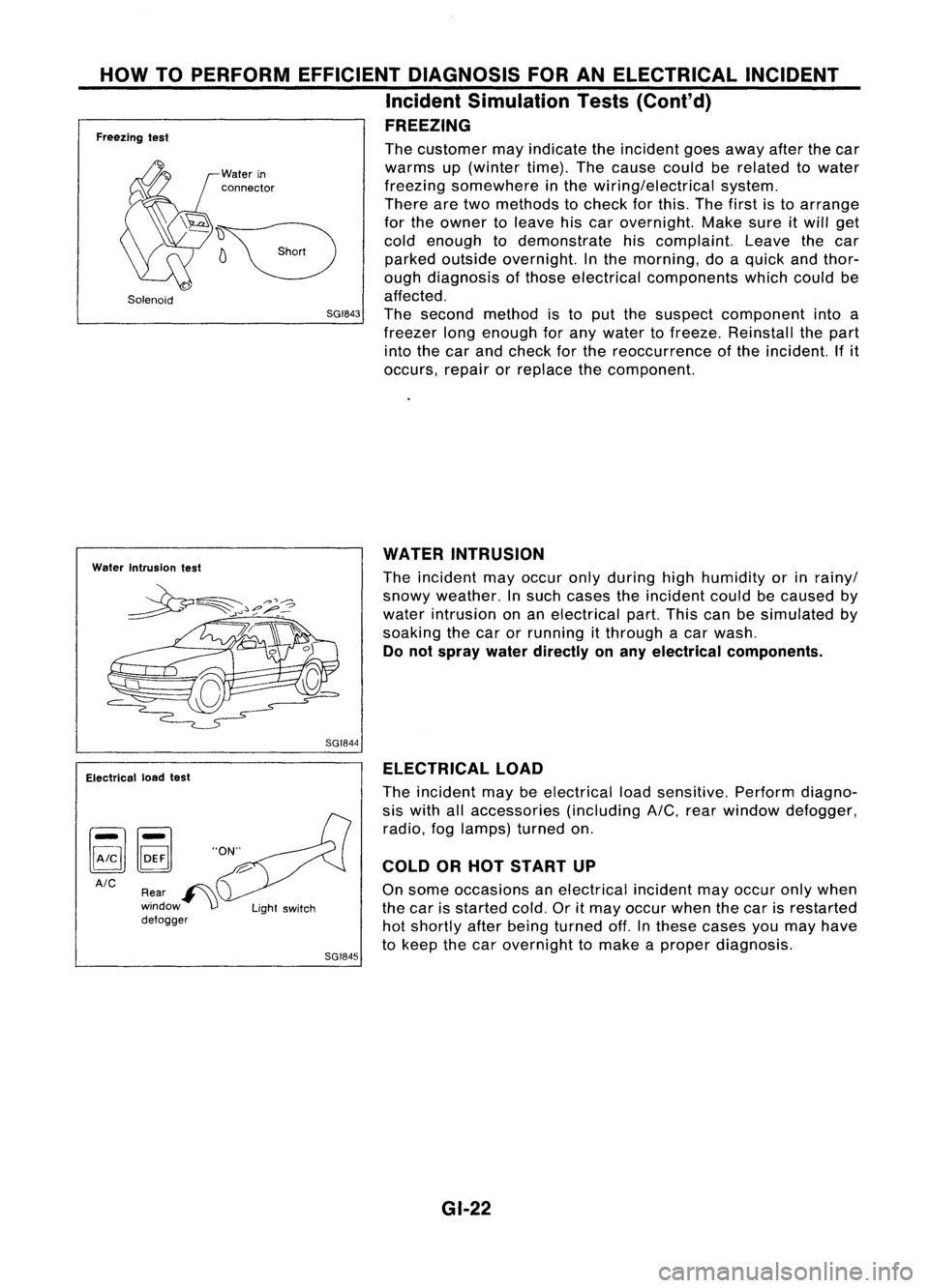
FREEZING
Freezing test
Solenoid
Water
in
connector
The
customer mayindicate theincident goesaway afterthecar
warms up(winter time).Thecause couldberelated towater
freezing somewhere inthe wiring/electrical system.
There aretwo methods tocheck forthis. Thefirst isto arrange
for the owner toleave hiscar overnight. Makesureitwill get
cold enough todemonstrate hiscomplaint. Leavethecar
parked outside overnight. Inthe morning, doaquick andthor-
ough diagnosis ofthose electrical components whichcouldbe
affected.
SGI843
Thesecond method isto put the suspect component intoa
freezer longenough forany water tofreeze. Reinstall thepart
into thecar and check forthe reoccurrence ofthe incident. Ifit
occurs, repairorreplace thecomponent.
Water Intrusion test
WATER
INTRUSION
The incident mayoccur onlyduring highhumidity orinrainy/
snowy weather. Insuch cases theincident couldbecaused by
water intrusion onan electrical part.Thiscanbesimulated by
soaking thecar orrunning itthrough acar wash.
Do not spray waterdirectly onany electrical components.
SGI844
Electrical loadtest
AIC SGI845ELECTRICAL
LOAD
The incident maybeelectrical loadsensitive. Performdiagno-
sis with allaccessories (includingA/C,rearwindow defogger,
radio, foglamps) turnedon.
COLD ORHOT START UP
On some occasions anelectrical incidentmayoccur onlywhen
the car isstarted cold.Oritmay occur whenthecar isrestarted
hot shortly afterbeing turned off.Inthese cases youmay have
to keep thecar overnight tomake aproper diagnosis.
GI-22