1995 JEEP YJ Grease fittings
[x] Cancel search: Grease fittingsPage 45 of 2158

(11) Remove the support and lower the vehicle.
DRIVE SHAFTS
Lubricate at the intervals described in the Mainte-
nance Schedule section of this Group. Refer to Group
16, Propeller Shafts for proper service procedures.
CAUTION: It is very important that drive shafts be
lubricated at periodic intervals and that the speci-
fied type of lubricant be used. Failure to properly
lubricate could result in premature wear of drive
shaft components.
LUBRICANT SPECIFICATION
Use Mopar, Multi-purpose Grease or any lubricate
that is identified as NLGI GC-LB lubricant.
RUBBER AND PLASTIC HOSES/TUBING
The condition of underbody rubber hose and plastic
tubing should be inspected whenever underbody ser-
vice is performed.
Rubber hoses and plastic tubing should be re-
placed immediately if there is any evidence of
failure.
HOSE/TUBING INSPECTION
(1) Inspect all hose and tubing fittings for loose-
ness and corrosion. Inspect the rubber hoses for brit-
tleness and cracks. Thoroughly inspect the hose ends
(those that are slipped over nipple connectors) for
splits (Fig. 10, 11, 12, 13, 14, 15 and 16).
(2) Inspect the surface of hoses and tubing for heat
and mechanical damage. Hose and tubing located
close to an exhaust pipe should be given special at-
tention.
(3) Inspect the rubber hose routing to ensure that
the hoses do not contact any heat source, moving
component, etc., that would potentially cause heat or
mechanical damage.
(4) Inspect all the hose connections to ensure that
they are secure and there is no fluid leakage. Actual
dripping of hot fluid should be noted and the clamps
tightened in an attempt to stop the leakage before re-
placing the hose.
Fig. 10 Front Axle Vent Hose (4WD)ÐXJ Vehicles
Fig. 9 Differential Housing Cover Installed
Fig. 11 Front Axle Vent HoseÐYJ Vehicles
0 - 26 LUBRICATION AND MAINTENANCEJ
Page 168 of 2158

(2) Disconnect brake lines at master cylinder and
combination valve.
(3) Remove nuts attaching master cylinder to
booster studs.
(4) Remove master cylinder.
(5) Remove cylinder cover and drain fluid.
(6) If two-piece master cylinder reservoir requires
service, refer to reservoir replacement procedure in
this section.
MASTER CYLINDER INSTALLATION (NON-ABS)
(1) Bleed master cylinder on bench before installa-
tion. Refer to procedure in this section.
(2) If new two-piece master cylinder is being in-
stalled, remove plastic protective sleeve from primary
piston shank. Also check condition of seal at rear of
cylinder body. Reposition seal if dislodged. Replace
seal if cut, or torn.
(3) Clean cylinder mounting surface of brake booster.
Use shop towel wetted with brake cleaner for this pur-
pose. Dirt, grease, or similar materials will prevent
proper cylinder seating and could result in vacuum leak.
(4) Slide master cylinder onto brake booster studs.
(5) Install nuts attaching master cylinder to booster
studs. Tighten nuts to 25 Nzm (220 in. lbs.) torque.
(6) Connect brakelines to master cylinder and com-
bination valve (Figs. 1 and 2).
(7) Fill and bleed brake system.
COMBINATION VALVE REPLACEMENT (NON-ABS)
The combination valve is not a repairable compo-
nent. The valve is serviced as an assembly whenever
diagnosis indicates replacement is necessary.
(1) Remove air cleaner cover and hose for access to
valve, if necessary.
(2) Disconnect differential pressure switch wire at
combination valve. Do not pull switch wire to discon-
nect. Unsnap connecter lock tabs to remove.
(3) Disconnect brakelines at combination valve and
remove valve.
(4) Connect brakelines to replacement valve. Start
line fittings by hand to avoid cross threading.
Tighten fittings snug but not to required torque at
this time.
(5) Connect wire to pressure differential switch.
(6) Bleed brakes.
(7) Tighten brakeline fittings to 18-24 Nzm
(160-210 in. lbs.) torque after bleeding.
MASTER CYLINDER OVERHAUL (4-CYLINDER
MODELS)
CYLINDER DISASSEMBLY
(1) Examine cylinder cover seal. Discard seal if
torn or distorted.
(2) Clamp cylinder in vise (Fig. 3).(3) Remove piston retaining snap ring. Press and
hold primary piston inward with wood dowel or sim-
ilar tool. Then remove snap ring (Fig. 4).
(4) Remove and discard primary piston (Fig. 5).
Piston is serviced only as assembly.
(5) Remove secondary piston (Fig. 6). Apply air
pressure through rear outlet port to ease piston out
of bore. Cover small ports at bottom of rear reservoir
with towel to prevent air leakage.
(6) Discard secondary piston. Do not disassemble
piston as components are only serviced as assembly.
MASTER CYLINDER CLEANING AND
INSPECTION
Clean the cylinder with Mopar brake cleaning sol-
vent or clean brake fluid. Remove cleaning residue
with compressed air.
Inspect the cylinder bore. A light discoloration of
Fig. 3 Mounting Cylinder In Vise
Fig. 4 Removing/Installing Piston Snap Ring
5 - 16 MASTER CYLINDERÐCOMBINATION VALVEJ
Page 180 of 2158
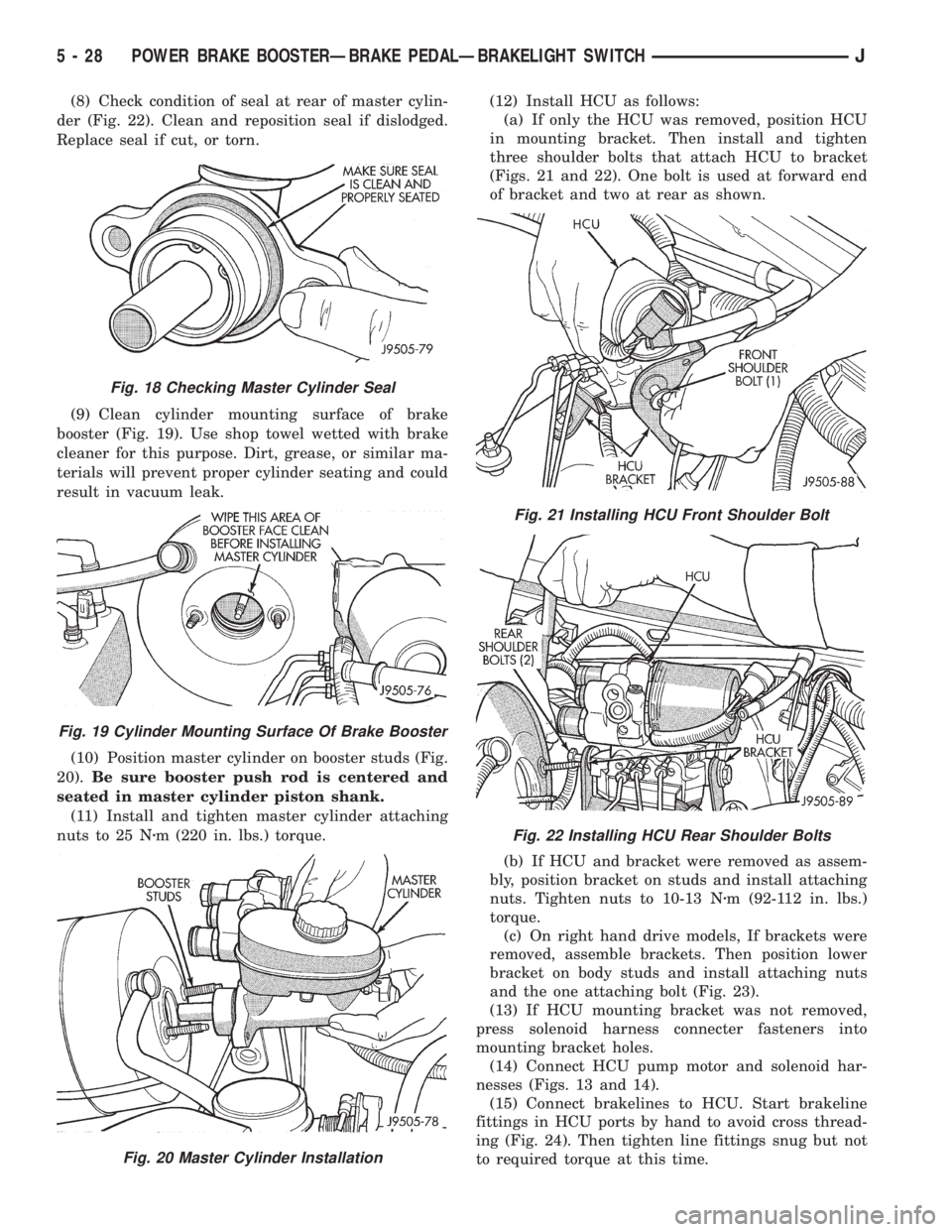
(8) Check condition of seal at rear of master cylin-
der (Fig. 22). Clean and reposition seal if dislodged.
Replace seal if cut, or torn.
(9) Clean cylinder mounting surface of brake
booster (Fig. 19). Use shop towel wetted with brake
cleaner for this purpose. Dirt, grease, or similar ma-
terials will prevent proper cylinder seating and could
result in vacuum leak.
(10) Position master cylinder on booster studs (Fig.
20).Be sure booster push rod is centered and
seated in master cylinder piston shank.
(11) Install and tighten master cylinder attaching
nuts to 25 Nzm (220 in. lbs.) torque.(12) Install HCU as follows:
(a) If only the HCU was removed, position HCU
in mounting bracket. Then install and tighten
three shoulder bolts that attach HCU to bracket
(Figs. 21 and 22). One bolt is used at forward end
of bracket and two at rear as shown.
(b) If HCU and bracket were removed as assem-
bly, position bracket on studs and install attaching
nuts. Tighten nuts to 10-13 Nzm (92-112 in. lbs.)
torque.
(c) On right hand drive models, If brackets were
removed, assemble brackets. Then position lower
bracket on body studs and install attaching nuts
and the one attaching bolt (Fig. 23).
(13) If HCU mounting bracket was not removed,
press solenoid harness connecter fasteners into
mounting bracket holes.
(14) Connect HCU pump motor and solenoid har-
nesses (Figs. 13 and 14).
(15) Connect brakelines to HCU. Start brakeline
fittings in HCU ports by hand to avoid cross thread-
ing (Fig. 24). Then tighten line fittings snug but not
to required torque at this time.
Fig. 18 Checking Master Cylinder Seal
Fig. 19 Cylinder Mounting Surface Of Brake Booster
Fig. 20 Master Cylinder Installation
Fig. 21 Installing HCU Front Shoulder Bolt
Fig. 22 Installing HCU Rear Shoulder Bolts
5 - 28 POWER BRAKE BOOSTERÐBRAKE PEDALÐBRAKELIGHT SWITCHJ
Page 182 of 2158
(11) Remove nuts attaching booster to passenger
compartment side of dash panel.
(12) In engine compartment, slide booster studs
out of dash panel, tilt booster upward, and remove
booster from engine compartment.
(13) Remove dash seal from booster.
(14) If booster is only being removed for access to
other components, cover booster front opening with
clean shop towel.
POWER BRAKE BOOSTER INSTALLATION (XJ
WITHOUT ABS)
(1) If original booster is being installed, test check
valve with vacuum tool before booster installation.
Replace check valve if it will not hold vacuum.
(2) Install dash seal on booster.
(3) Align and position booster on dash panel (Fig.
17).
(4) In passenger compartment, install nuts that at-
tach booster to dash panel. Tighten nuts just enough
to hold booster in place.
(5) Slide booster push rod onto brake pedal. Then
secure push rod to pedal pin with retaining clip.
(6) Tighten booster attaching nuts to 41 Nzm (30 ft.
lbs.) on XJ and 34 Nzm (25 ft. lbs.) on YJ.
(7) Install instrument panel lower trim cover.
(8) If original master cylinder is being installed,
check condition of seal at rear of master cylinder
(Fig. 18). Clean and reposition seal if dislodged. Re-
place seal if cut, or torn.
(9) Clean cylinder mounting surface of brake
booster. Use shop towel wetted with brake cleaner for
this purpose. Dirt, grease, or similar materials will
prevent proper cylinder seating and could result in
vacuum leak.
(10) Align and install master cylinder on booster
studs. Tighten cylinder attaching nuts to 13-25 Nzm
(115-220 in. lbs.) torque.
(11) Connect vacuum hose to booster check valve.
(12) Connect and secure brakelines to combination
valve and master cylinder. Start all brakeline fittings
by hand to avoid cross threading.
(13) If combination valve has integral bracket, po-
sition bracket on booster studs. Then install and
tighten bracket attaching nuts to 13-25 Nzm (115-220
in. lbs.) torque.
(14) Connect wire to combination valve switch.
(15) Top off master cylinder fluid level.
(16) Bleed brakes. Refer to procedures in section
on brake bleeding.
(17) Install engine air cleaner and hoses.
(18) Verify proper brake operation before moving
vehicle.
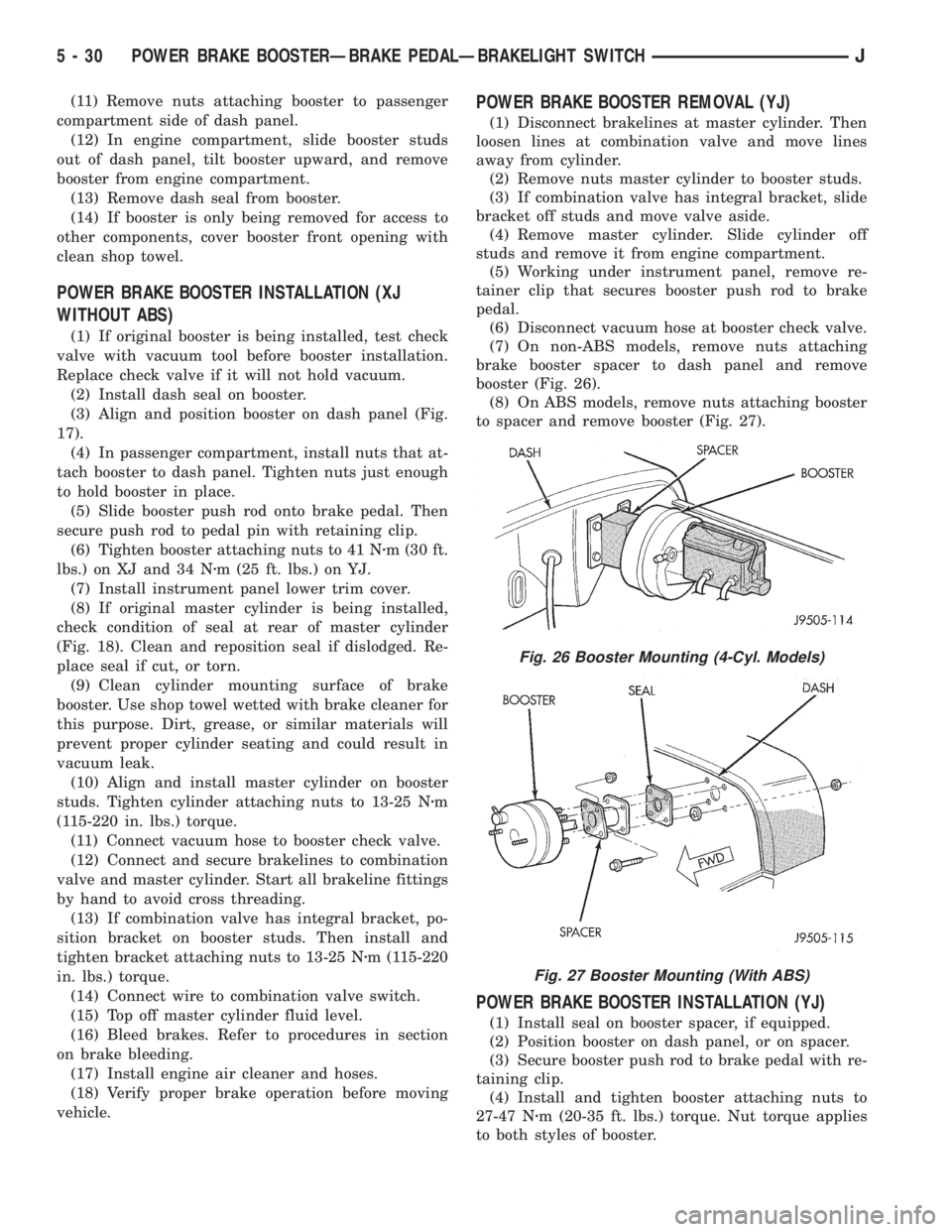
POWER BRAKE BOOSTER REMOVAL (YJ)
(1) Disconnect brakelines at master cylinder. Then
loosen lines at combination valve and move lines
away from cylinder.
(2) Remove nuts master cylinder to booster studs.
(3) If combination valve has integral bracket, slide
bracket off studs and move valve aside.
(4) Remove master cylinder. Slide cylinder off
studs and remove it from engine compartment.
(5) Working under instrument panel, remove re-
tainer clip that secures booster push rod to brake
pedal.
(6) Disconnect vacuum hose at booster check valve.
(7) On non-ABS models, remove nuts attaching
brake booster spacer to dash panel and remove
booster (Fig. 26).
(8) On ABS models, remove nuts attaching booster
to spacer and remove booster (Fig. 27).
POWER BRAKE BOOSTER INSTALLATION (YJ)
(1) Install seal on booster spacer, if equipped.
(2) Position booster on dash panel, or on spacer.
(3) Secure booster push rod to brake pedal with re-
taining clip.
(4) Install and tighten booster attaching nuts to
27-47 Nzm (20-35 ft. lbs.) torque. Nut torque applies
to both styles of booster.
Fig. 26 Booster Mounting (4-Cyl. Models)
Fig. 27 Booster Mounting (With ABS)
5 - 30 POWER BRAKE BOOSTERÐBRAKE PEDALÐBRAKELIGHT SWITCHJ
Page 183 of 2158
(5) Connect vacuum hose to brake booster check
valve.
(6) Install master cylinder and combination valve.
(7) Bleed brakes. Then tighten brakeline fittings to
15-18 Nzm (130-160 in. lbs.) at master cylinder and
18-24 Nzm (160-210 in. lbs.) at combination valve.
BRAKE PEDAL REMOVAL
(1) Remove lower trim panel and A/C duct if nec-
essary.
(2) Remove steering column lower trim panel and
bezel.(3) Remove necessary dash panel-to-instrument
panel brace rods.
(4) Disconnect and remove brakelight switch.
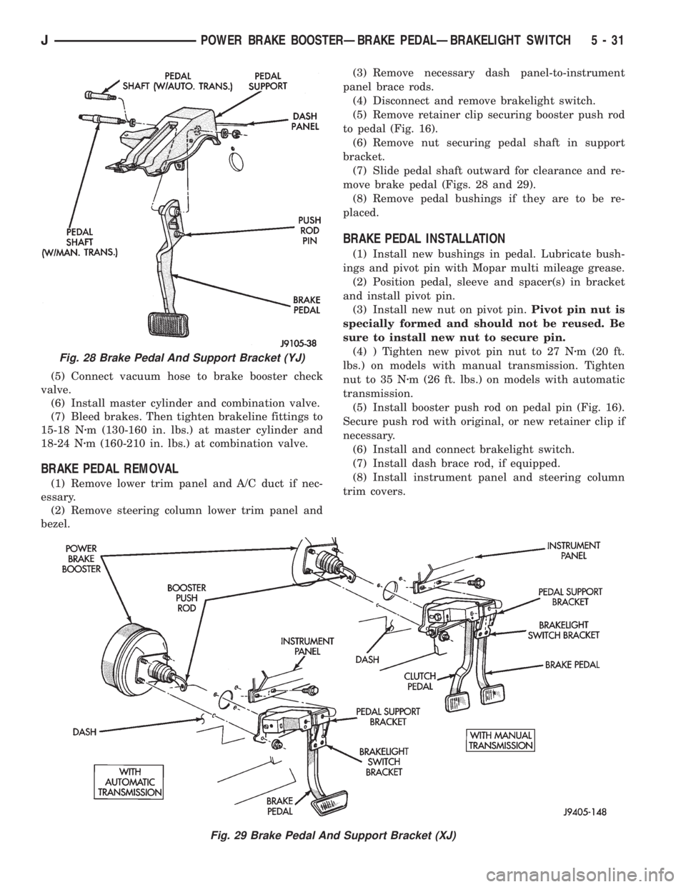
(5) Remove retainer clip securing booster push rod
to pedal (Fig. 16).
(6) Remove nut securing pedal shaft in support
bracket.
(7) Slide pedal shaft outward for clearance and re-
move brake pedal (Figs. 28 and 29).
(8) Remove pedal bushings if they are to be re-
placed.
BRAKE PEDAL INSTALLATION
(1) Install new bushings in pedal. Lubricate bush-
ings and pivot pin with Mopar multi mileage grease.
(2) Position pedal, sleeve and spacer(s) in bracket
and install pivot pin.
(3) Install new nut on pivot pin.Pivot pin nut is
specially formed and should not be reused. Be
sure to install new nut to secure pin.
(4) ) Tighten new pivot pin nut to 27 Nzm (20 ft.
lbs.) on models with manual transmission. Tighten
nut to 35 Nzm (26 ft. lbs.) on models with automatic
transmission.
(5) Install booster push rod on pedal pin (Fig. 16).
Secure push rod with original, or new retainer clip if
necessary.
(6) Install and connect brakelight switch.
(7) Install dash brace rod, if equipped.
(8) Install instrument panel and steering column
trim covers.
Fig. 28 Brake Pedal And Support Bracket (YJ)
Fig. 29 Brake Pedal And Support Bracket (XJ)
JPOWER BRAKE BOOSTERÐBRAKE PEDALÐBRAKELIGHT SWITCH 5 - 31
Page 1674 of 2158
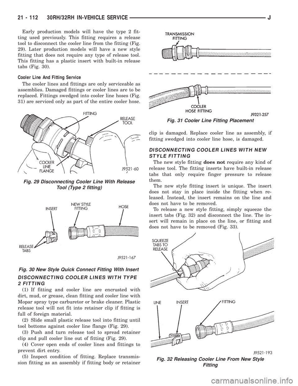
Early production models will have the type 2 fit-
ting used previously. This fitting requires a release
tool to disconnect the cooler line from the fitting (Fig.
29). Later production models will have a new style
fitting that does not require any type of release tool.
This fitting has a plastic insert with built-in release
tabs (Fig. 30).
Cooler Line And Fitting Service
The cooler lines and fittings are only serviceable as
assemblies. Damaged fittings or cooler lines are to be
replaced. Fittings swedged into cooler line hoses (Fig.
31) are serviced only as part of the entire cooler hose.
DISCONNECTING COOLER LINES WITH TYPE
2 FITTING
(1) If fitting and cooler line are encrusted with
dirt, mud, or grease, clean fitting and cooler line with
Mopar spray type carburetor or brake cleaner. Plastic
release tool will not fit into retainer clip if fitting is
full of foreign material.
(2) Slide small plastic release tool into fitting until
tool bottoms against cooler line flange (Fig. 29).
(3) Push and turn release tool to spread retainer
clip and pull cooler line out of fitting (Fig. 29).
(4) Cover open ends of cooler lines and fittings to
prevent dirt entry.
(5) Inspect condition of fitting. Replace transmis-
sion fitting as an assembly if fitting body or retainerclip is damaged. Replace cooler line as assembly, if
fitting swedged into cooler line hose, is damaged.
DISCONNECTING COOLER LINES WITH NEW
STYLE FITTING
The new style fittingdoes notrequire any kind of
release tool. The fitting inserts have built-in release
tabs that only require finger pressure to release
them.
The new style fitting insert is unique. The insert
does not stay in place inside the fitting when re-
leased. Instead, the insert remains on the line and
does not have to be removed.
To release a new style fitting, simply squeeze the
insert tabs (Fig. 32) and disconnect the line. The in-
sert will remain in place on the line, or fitting and
does not have to be removed (Fig. 33).
Fig. 30 New Style Quick Connect Fitting With Insert
Fig. 29 Disconnecting Cooler Line With Release
Tool (Type 2 fitting)
Fig. 31 Cooler Line Fitting Placement
Fig. 32 Releasing Cooler Line From New Style
Fitting
21 - 112 30RH/32RH IN-VEHICLE SERVICEJ