1995 JEEP YJ Horn and turn signal switch
[x] Cancel search: Horn and turn signal switchPage 428 of 2158
allowing current flow to the lamps. As the bimetal
strip cools, the contact points are pushed open and
the cycle repeats.
COMBINATION FLASHER (XJ ONLY)
The combination flasher functions as both the turn
signal and hazard warning flasher on XJ models. The
combination flasher is a smart relay that is located in
the relay center under the lower instrument panel
and inboard of the steering column. The combination
flasher can not be repaired. If faulty, it must be
replaced.
The combination flasher is designed to handle the
current flow requirements of the factory installed
lighting. If supplemental lighting is added to the turn
signal circuits such as when towing a trailer with
lights, the combination flasher will automatically
compensate. This allows the flash rate to remain the
same, regardless of electrical load increases. However,
if a bulb fails in the turn signal or hazard warning
circuits, the flash rate of the remaining bulbs in that
circuit will increase to 120 flashes per minute or
higher.
TURN SIGNAL/HAZARD WARNING SWITCH
(YJ ONLY)
The turn signal and hazard warning switches are
combined into a single unit mounted within the upper
steering column bowl and beneath the steering wheel.
The turn signal lever on the left side of the steering
column is moved up or down to select the right or left
turn signal switch position. The turn signals will only
operate with the ignition switch in the ACCESSORY
or ON position.
The hazard warning button on the right side of the
steering column is pushed in to turn the hazard
warning system on, or pulled out to turn the system
off. The hazard warning system will operate regard-
less of ignition switch position. The turn signal/haz-
ard warning switch can not be repaired. If faulty, the
entire unit must be replaced.
MULTI-FUNCTION SWITCH (XJ ONLY)
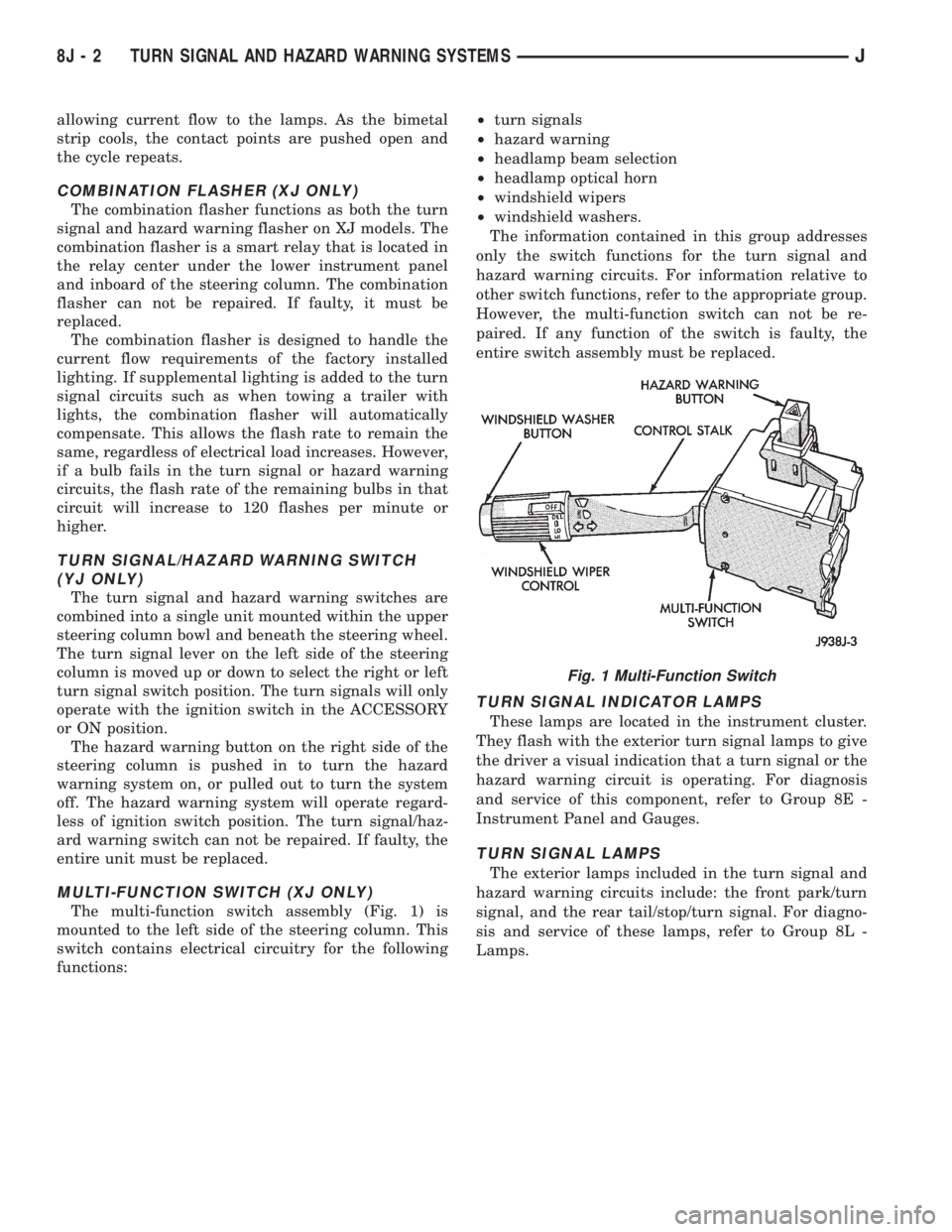
The multi-function switch assembly (Fig. 1) is
mounted to the left side of the steering column. This
switch contains electrical circuitry for the following
functions:²turn signals
²hazard warning
²headlamp beam selection
²headlamp optical horn
²windshield wipers
²windshield washers.
The information contained in this group addresses
only the switch functions for the turn signal and
hazard warning circuits. For information relative to
other switch functions, refer to the appropriate group.
However, the multi-function switch can not be re-
paired. If any function of the switch is faulty, the
entire switch assembly must be replaced.
TURN SIGNAL INDICATOR LAMPS
These lamps are located in the instrument cluster.
They flash with the exterior turn signal lamps to give
the driver a visual indication that a turn signal or the
hazard warning circuit is operating. For diagnosis
and service of this component, refer to Group 8E -
Instrument Panel and Gauges.
TURN SIGNAL LAMPS
The exterior lamps included in the turn signal and
hazard warning circuits include: the front park/turn
signal, and the rear tail/stop/turn signal. For diagno-
sis and service of these lamps, refer to Group 8L -
Lamps.
Fig. 1 Multi-Function Switch
8J - 2 TURN SIGNAL AND HAZARD WARNING SYSTEMSJ
Page 431 of 2158
SERVICE PROCEDURES
WARNING: ON VEHICLES EQUIPPED WITH AN AIRBAG,
REFER TO GROUP 8M - RESTRAINT SYSTEMS BEFORE
ATTEMPTING STEERING WHEEL COMPONENT DIAGNO-
SIS OR SERVICE. FAILURE TO TAKE PROPER PRECAU-
TIONS COULD RESULT IN ACCIDENTAL AIRBAG DE-
PLOYMENT AND POSSIBLE PERSONAL INJURY.
MULTI-FUNCTION SWITCH REMOVE/INSTALL - XJ
(1) Disconnect battery negative cable.
(2) Remove tilt lever (if equipped).
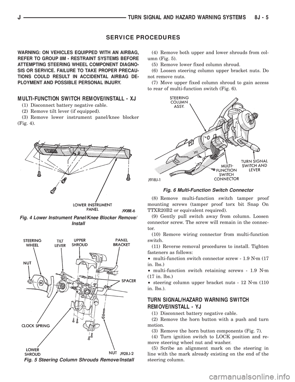
(3) Remove lower instrument panel/knee blocker
(Fig. 4).(4) Remove both upper and lower shrouds from col-
umn (Fig. 5).
(5) Remove lower fixed column shroud.
(6) Loosen steering column upper bracket nuts. Do
not remove nuts.
(7) Move upper fixed column shroud to gain access
to rear of multi-function switch (Fig. 6).
(8) Remove multi-function switch tamper proof
mounting screws (tamper proof torx bit Snap On
TTXR20B2 or equivalent required).
(9) Gently pull switch away from column. Loosen
connector screw. The screw will remain in the connec-
tor.
(10) Remove wiring connector from multi-function
switch.
(11) Reverse removal procedures to install. Tighten
fasteners as follows:
²multi-function switch connector screw - 1.9 Nzm (17
in. lbs.)
²multi-function switch retaining screws - 1.9 Nzm
(17 in. lbs.)
²steering column upper bracket nuts - 12 Nzm(110
in. lbs.).
TURN SIGNAL/HAZARD WARNING SWITCH
REMOVE/INSTALL - YJ
(1) Disconnect battery negative cable.
(2) Remove the horn button with a push and turn
motion.
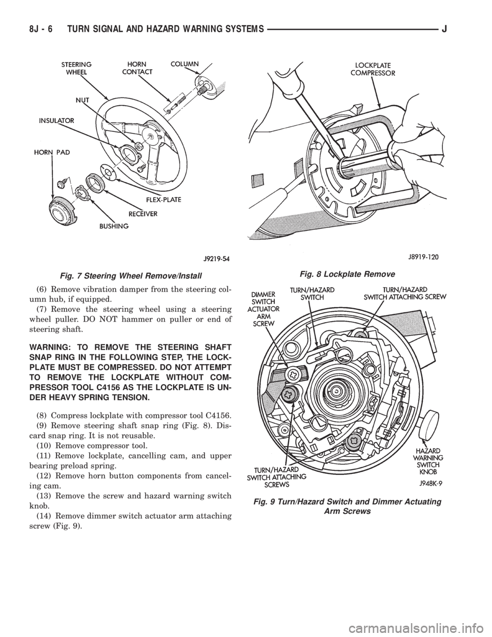
(3) Remove the horn button components (Fig. 7).
(4) Turn ignition switch to LOCK position and re-
move steering wheel nut and washer.
(5) Scribe an alignment mark on the steering in
line with the mark already existing on the end of the
steering column.
Fig. 5 Steering Column Shrouds Remove/Install
Fig. 4 Lower Instrument Panel/Knee Blocker Remove/
Install
Fig. 6 Multi-Function Switch Connector
JTURN SIGNAL AND HAZARD WARNING SYSTEMS 8J - 5
Page 432 of 2158
(6) Remove vibration damper from the steering col-
umn hub, if equipped.
(7) Remove the steering wheel using a steering
wheel puller. DO NOT hammer on puller or end of
steering shaft.
WARNING: TO REMOVE THE STEERING SHAFT
SNAP RING IN THE FOLLOWING STEP, THE LOCK-
PLATE MUST BE COMPRESSED. DO NOT ATTEMPT
TO REMOVE THE LOCKPLATE WITHOUT COM-
PRESSOR TOOL C4156 AS THE LOCKPLATE IS UN-
DER HEAVY SPRING TENSION.
(8) Compress lockplate with compressor tool C4156.
(9) Remove steering shaft snap ring (Fig. 8). Dis-
card snap ring. It is not reusable.
(10) Remove compressor tool.
(11) Remove lockplate, cancelling cam, and upper
bearing preload spring.
(12) Remove horn button components from cancel-
ing cam.
(13) Remove the screw and hazard warning switch
knob.
(14) Remove dimmer switch actuator arm attaching
screw (Fig. 9).
Fig. 7 Steering Wheel Remove/InstallFig. 8 Lockplate Remove
Fig. 9 Turn/Hazard Switch and Dimmer Actuating
Arm Screws
8J - 6 TURN SIGNAL AND HAZARD WARNING SYSTEMSJ
Page 543 of 2158

WIRING DIAGRAMS
CONTENTS
page page
8W-01 GENERAL INFORMATIONÐWIRING
DIAGRAMS.................... 8W-01-1
8W-10 FUSE/FUSE BLOCK........... 8W-10-1
8W-11 POWER DISTRIBUTION........ 8W-11-1
8W-15 GROUND DISTRIBUTION....... 8W-15-1
8W-20 CHARGING SYSTEM.......... 8W-20-1
8W-21 STARTING SYSTEM........... 8W-21-1
8W-30 FUEL/IGNITION.............. 8W-30-1
8W-31 TRANSMISSION CONTROLS.... 8W-31-1
8W-32 ANTI-LOCK BRAKES.......... 8W-32-1
8W-33 VEHICLE SPEED CONTROL..... 8W-33-1
8W-40 INSTRUMENT CLUSTER....... 8W-40-1
8W-41 HORN/CIGAR LIGHTER......... 8W-41-1
8W-42 AIR CONDITIONING/HEATER.... 8W-42-1
8W-44 INTERIOR LIGHTING.......... 8W-44-1
8W-47 AUDIO SYSTEM.............. 8W-47-18W-48 HEATED REAR WINDOW....... 8W-48-1
8W-49 OVERHEAD CONSOLE......... 8W-49-1
8W-50 FRONT LIGHTING............. 8W-50-1
8W-51 REAR LIGHTING............. 8W-51-1
8W-52 TURN SIGNALS.............. 8W-52-1
8W-53 WIPERS..................... 8W-53-1
8W-54 TRAILER TOW................ 8W-54-1
8W-60 POWER WINDOWS.......... 8W-60-1
8W-61 POWER DOOR LOCKS......... 8W-61-1
8W-62 POWER MIRRORS............ 8W-62-1
8W-63 POWER SEAT................ 8W-63-1
8W-70 SPLICE INFORMATION........ 8W-70-1
8W-80 CONNECTOR PIN OUTS....... 8W-80-1
8W-90 CONNECTOR LOCATIONS...... 8W-90-1
8W-95 SPLICE LOCATIONS........... 8W-95-1
HOW TO USE THIS GROUP
The purpose of this group is to show the electrical
circuits in a clear, simple fashion and to make trou-
bleshooting easier. Components that work together
are shown together. All electrical components used in
a specific system are shown on one diagram. The feed
for a system is shown at the top of the page. All
wires, connectors, splices, and components are shown
in the flow of current to the bottom of the page. Wir-
ing which is not part of the circuit represented is ref-
erenced to another page/section, where the complete
circuit is shown. In addition, all switches, compo-
nents, and modules are shown in theat rest posi-
tion with the doors closed and the key removed
from the ignition.
If a component is part of several different circuits,
it is shown in the diagram for each. For example, the
headlamp switch is the main part of the exterior
lighting, but it also affects the interior lighting and
the chime warning system.
It is important to realize that no attempt is
made on the diagrams to represent components
and wiring as they appear on the vehicle. For
example, a short piece of wire is treated the
same as a long one. In addition, switches and
other components are shown as simply as pos-
sible, with regard to function only.
The wiring diagram show circuits for all wheel-
bases. If there is a difference in systems or compo-
nents between wheel-bases, an identifier is placed
next to the component.
SECTION IDENTIFICATION
Sections in Group 8W are organized by sub-sys-
tems. The sections contain circuit operation descrip-
tions, helpful information, and system diagrams. The
intention is to organize information by system, con-
sistently from year to year.
CONNECTOR LOCATIONS
Section 8W-90 contains Connector Location illus-
trations. The illustrations contain the connector
number and component identification. Connector Lo-
cation charts in Section 8W-90 reference the illustra-
tion number for components and connectors.
Section 8W-80 shows each connector and the cir-
cuits involved with that connector. The connectors
are identified using the number on the Diagram
pages.
SPLICE LOCATIONS
Splice Location charts in Section 8W-70 show the
entire splice, and provide references to other sections
the splice serves.
Section 8W-95 contains illustrations that show the
general location of the splices in each harness. The
illustrations show the splice by number, and provide
a written location.
JWIRING DIAGRAMSÐXJ VEHICLES 8W - 1 - 1
Page 819 of 2158

WIRING DIAGRAMS
CONTENTS
page page
8W-01 GENERAL INFORMATIONÐWIRING
DIAGRAMS...................... 8W-01-1
8W-10 FUSE/FUSE BLOCK........... 8W-10-1
8W-11 POWER DISTRIBUTION........ 8W-11-1
8W-15 GROUND DISTRIBUTION....... 8W-15-1
8W-20 CHARGING SYSTEM.......... 8W-20-1
8W-21 STARTING SYSTEM........... 8W-21-1
8W-30 FUEL/IGNITION.............. 8W-30-1
8W-31 TRANSMISSION CONTROLS.... 8W-31-1
8W-32 ANTI-LOCK BRAKES........... 8W-32-1
8W-33 VEHICLE SPEED CONTROL..... 8W-33-1
8W-40 INSTRUMENT CLUSTER....... 8W-40-1
8W-41 HORN/CIGAR LIGHTER........ 8W-41-1
8W-42 AIR CONDITIONING/HEATER.... 8W-42-1
8W-44 INTERIOR LIGHTING.......... 8W-44-1
8W-47 AUDIO SYSTEM.............. 8W-47-18W-48 HEATED REAR WINDOW....... 8W-48-1
8W-49 OVERHEAD CONSOLE.......... 8W-49-1
8W-50 FRONT LIGHTING............ 8W-50-1
8W-51 REAR LIGHTING............. 8W-51-1
8W-52 TURN SIGNALS.............. 8W-52-1
8W-53 WIPERS.................... 8W-53-1
8W-54 TRAILER TOW................ 8W-54-1
8W-60 POWER WINDOWS............ 8W-60-1
8W-61 POWER DOOR LOCKS......... 8W-61-1
8W-62 POWER MIRRORS............ 8W-62-1
8W-63 POWER SEAT................ 8W-63-1
8W-70 SPLICE INFORMATION........ 8W-70-1
8W-80 CONNECTOR PIN OUTS....... 8W-80-1
8W-90 CONNECTOR LOCATIONS...... 8W-90-1
8W-95 SPLICE LOCATIONS........... 8W-95-1
HOW TO USE THIS GROUP
The purpose of this group is to show the electrical
circuits in a clear, simple fashion and to make trou-
bleshooting easier. Components that work together
are shown together. All electrical components used in
a specific system are shown on one diagram. The feed
for a system is shown at the top of the page. All
wires, connectors, splices, and components are shown
in the flow of current to the bottom of the page. Wir-
ing which is not part of the circuit represented is ref-
erenced to another page/section, where the complete
circuit is shown. In addition, all switches, compo-
nents, and modules are shown in theat rest posi-
tion with the doors closed and the key removed
from the ignition.
If a component is part of several different circuits,
it is shown in the diagram for each. For example, the
headlamp switch is the main part of the exterior
lighting, but it also affects the interior lighting and
the chime warning system.
It is important to realize that no attempt is
made on the diagrams to represent components
and wiring as they appear on the vehicle. For
example, a short piece of wire is treated the
same as a long one. In addition, switches and
other components are shown as simply as pos-
sible, with regard to function only.
The wiring diagram show circuits for all wheel-
bases. If there is a difference in systems or compo-
nents between wheel-bases, an identifier is placed
next to the component.
SECTION IDENTIFICATION
Sections in Group 8W are organized by sub-sys-
tems. The sections contain circuit operation descrip-
tions, helpful information, and system diagrams. The
intention is to organize information by system, con-
sistently from year to year.
CONNECTOR LOCATIONS
Section 8W-90 contains Connector Location illus-
trations. The illustrations contain the connector
number and component identification. Connector Lo-
cation charts in Section 8W-90 reference the illustra-
tion number for components and connectors.
Section 8W-80 shows each connector and the cir-
cuits involved with that connector. The connectors
are identified using the number on the Diagram
pages.
SPLICE LOCATIONS
Splice Location charts in Section 8W-70 show the
entire splice, and provide references to other sections
the splice serves.
Section 8W-95 contains illustrations that show the
general location of the splices in each harness. The
illustrations show the splice by number, and provide
a written location.
JWIRING DIAGRAMSÐXJ-RHD 8W - 1 - 1
Page 833 of 2158
POWER DISTRIBUTION
GENERAL INFORMATION
This section covers the Power Distribution Center
(PDC) and all circuits involved with it. For additional
information on system operation, refer to the appro-
priate section of the wiring diagrams.
DIAGRAM INDEX
Component Page
A/C Compressor Clutch Relay..............8W-11-3, 11
ABS Control Module.....................8W-11-6, 7
ABS Power Relay......................8W-11-3, 6
ABS Pump Motor Relay..................8W-11-3, 7
Automatic Shut Down Relay................8W-11-3, 9
Chime/Buzzer Module...................8W-11-5, 10
Dimming Relay.........................8W-11-16
Engine Starter Motor Relay................8W-11-3, 4
Fuel Pump Relay.......................8W-11-3, 8
Fuse 1 (Fuse Block)......................8W-11-13
Fuse 1 (PDC)..........................8W-11-13
Fuse 2 (Fuse Block).......................8W-11-4
Fuse 2 (PDC)...........................8W-11-8
Fuse 3 (PDC)..........................8W-11-12
Fuse 4 (PDC)..........................8W-11-14
Fuse 5 (PDC)...........................8W-11-5
Fuse 6 (PDC)....................8W-11-4, 7, 10, 14
Fuse 7 (PDC)...........................8W-11-4
Fuse 8 (Fuse Block).......................8W-11-7
Fuse 8 (PDC)...........................8W-11-7
Fuse 9 (Fuse Block).......................8W-11-5
Fuse 9 (PDC)..........................8W-11-13
Fuse 10 (Fuse Block)......................8W-11-5
Fuse 11 (PDC).........................8W-11-10
Fuse 12 (PDC).........................8W-11-14Component Page
Fuse 13 (PDC)..........................8W-11-4
Fuse 14 (PDC)..........................8W-11-8
Fuse 15 (PDC)..........................8W-11-8
Fuse 16 (PDC).........................8W-11-12
Fuse 26 (Fuse Block).....................8W-11-10
Headlamp Delay Module...................8W-11-10
Headlamp Delay Relay.....................8W-11-5
Headlamp Relay.........................8W-11-16
Headlamp Switch.........................8W-11-5
Heated Rear Window Relay.................8W-11-17
Horn Relay............................8W-11-16
Ignition Switch......................8W-11-4, 7, 14
In-Line Circuit Breaker (Stop Lamp Relay)........8W-11-13
LCD Illumination Relay....................8W-11-16
Overhead Console.....................8W-11-5, 10
Power Antenna Relay.....................8W-11-17
Power Distribution Center...................8W-11-2
Power Door Unlock Relay..................8W-11-15
Power Door Lock Relay...................8W-11-15
Powertrain Control Module............8W-11-4, 8, 9, 11
Radiator Fan Control Relay................8W-11-3, 11
Relay Center...........................8W-11-15
Telltale Connector (Instrument Cluster)........8W-11-6, 10
Transmission Control Module..............8W-11-8, 14
Turn Signal Relay.......................8W-11-17
J8W-11 POWER DISTRIBUTIONÐXJ-RHD 8W - 11 - 1
Page 1094 of 2158
WIRING DIAGRAMS
CONTENTS
page page
8W-01 GENERAL INFORMATIONÐWIRING
DIAGRAMS...................... 8W-01-1
8W-10 FUSE/FUSE BLOCK........... 8W-10-1
8W-11 POWER DISTRIBUTION........ 8W-11-1
8W-15 GROUND DISTRIBUTION....... 8W-15-1
8W-20 CHARGING SYSTEM.......... 8W-20-1
8W-21 STARTING SYSTEM........... 8W-21-1
8W-30 FUEL/IGNITION.............. 8W-30-1
8W-31 TRANSMISSION CONTROLS.... 8W-31-1
8W-32 ANTI-LOCK BRAKES.......... 8W-32-1
8W-40 INSTRUMENT CLUSTER....... 8W-40-1
8W-41 HORN/CIGAR LIGHTER........ 8W-41-18W-42 AIR CONDITIONING/HEATER.... 8W-42-1
8W-44 INTERIOR LIGHTING.......... 8W-44-1
8W-47 AUDIO SYSTEM.............. 8W-47-1
8W-48 HEATED REAR WINDOW....... 8W-48-1
8W-50 FRONT LIGHTING............ 8W-50-1
8W-51 REAR LIGHTING............. 8W-51-1
8W-52 TURN SIGNALS.............. 8W-52-1
8W-53 WIPERS.................... 8W-53-1
8W-70 SPLICE INFORMATION........ 8W-70-1
8W-80 CONNECTOR PIN OUTS....... 8W-80-1
8W-90 CONNECTOR LOCATIONS...... 8W-90-1
8W-95 SPLICE LOCATIONS........... 8W-95-1
HOW TO USE THIS GROUP
The purpose of this group is to show the electrical
circuits in a clear, simple fashion and to make trou-
bleshooting easier. Components that work together
are shown together. All electrical components used in
a specific system are shown on one diagram. The feed
for a system is shown at the top of the page. All
wires, connectors, splices, and components are shown
in the flow of current to the bottom of the page. Wir-
ing which is not part of the circuit represented is ref-
erenced to another page/section, where the complete
circuit is shown. In addition, all switches, compo-
nents, and modules are shown in theat rest posi-
tion with the doors closed and the key removed
from the ignition.
If a component is part of several different circuits,
it is shown in the diagram for each. For example, the
headlamp switch is the main part of the exterior
lighting, but it also affects the interior lighting and
the chime warning system.
It is important to realize that no attempt is
made on the diagrams to represent components
and wiring as they appear on the vehicle. For
example, a short piece of wire is treated the
same as a long one. In addition, switches and
other components are shown as simply as pos-
sible, with regard to function only.
The wiring diagram show circuits for all wheel-
bases. If there is a difference in systems or compo-
nents between wheel-bases, an identifier is placed
next to the component.
SECTION IDENTIFICATION
Sections in Group 8W are organized by sub-sys-
tems. The sections contain circuit operation descrip-
tions, helpful information, and system diagrams. The
intention is to organize information by system, con-
sistently from year to year.
CONNECTOR LOCATIONS
Section 8W-90 contains Connector Location illus-
trations. The illustrations contain the connector
number and component identification. Connector Lo-
cation charts in Section 8W-90 reference the illustra-
tion number for components and connectors.
Section 8W-80 shows each connector and the cir-
cuits involved with that connector. The connectors
are identified using the number on the Diagram
pages.
SPLICE LOCATIONS
Splice Location charts in Section 8W-70 show the
entire splice, and provide references to other sections
the splice serves.
Section 8W-95 contains illustrations that show the
general location of the splices in each harness. The
illustrations show the splice by number, and provide
a written location.
JWIRING DIAGRAMSÐÐYJ VEHICLES 8W - 1 - 1
Page 1155 of 2158
MALFUNCTION INDICATOR (CHECK ENGINE)
LAMP
The Powertrain Control Module (PCM) provides
ground for the malfunction indicator (Check Engine)
lamp on circuit G3. Circuit G3 connects to cavity 32
of the PCM. Circuit G5 connects to the instrument
cluster and supplies battery voltage for the malfunc-
tion indicator lamp. When illuminated, the malfunc-
tion indicator lamp displays the message CHECK
ENGINE.
For information regarding diagnostic trouble code
access using the malfunction indicator lamp, refer to
Group 14, Fuel Systems.
UP-SHIFT LAMP
On vehicles equipped with a manual transmission,
the Powertrain Control Module (PCM) provides
ground for the Up-Shift lamp on circuit K54. Circuit
G5 provides battery voltage for the lamp.
ABS WARNING LAMP
Circuit G5 provides power for the ABS warning
lamp at the instrument cluster. Ground for the ABS
warning lamp is provided by either the ABS control
module or by the ABS power relay when the relay is
not energized. The ABS control module illuminates
the lamp by providing ground on circuit G19.
Circuit G19 splices to connect to circuit B15
through a diode. When the ABS power relay is not
energized, it connects circuit B15 to circuit Z12. The
ground path for the warning lamp is provided
through the diode to circuit B15, through the ABS
power relay to ground on circuit Z12.
The diode between circuit G19 and B15 prevents
voltage from flowing to the ABS control module when
the ABS power relay switches to supply power on cir-
cuit B15.
BRAKE WARNING LAMP
Circuit G5 provides battery voltage for the brake
warning lamp. Circuit G11 can provide ground for
the lamp in 3 ways. The first ground path is through
the ignition switch when the key is in the START po-
sition.
The second ground path for the brake warning
lamp on circuit G11 is through the case grounded
brake warning switch. When the switch closes it pro-
vides a ground.
The third ground path on circuit G11 is through
the case grounded park brake switch. When the
switch closes it provides ground.
HIGH BEAM INDICATOR LAMP
Circuit G34 supplies power for the high-beam indi-
cator lamp when the operator either flashes the opti-
cal horn (high beams) or selects high beam operation.
Circuit Z1 provides the ground path for the lamp.
Circuit L3 from the headlamp switch powers the
high beam circuits of the headlamps. On vehicles not
equipped with Daytime Running Lamps (DRL), cir-
cuit G34 double crimps to circuit L3 at the bulkhead
connector.
On vehicles equipped with DRL, circuit L3 splices
to the DRL module. The DRL module powers circuit
G34.
TURN SIGNAL INDICATOR LAMPS
Circuit L61 supplies battery voltage to the left turn
signal indicator lamp. The right turn signal indicator
lamp receives battery voltage from circuit L60. The
turn signal/hazard flasher switch powers circuits L60
and L61. Circuit Z1 provides ground for the lamps.
HELPFUL INFORMATION
²If the warning lamps, gauges and indicator lamps
don't operate, check fuse 4 in the PDC and fuse 9 in
the fuse block.
²If the illumination lamps don't operate, check fuse
10 in the fuse block.
DIAGRAM INDEX
Component Page
4WD Switch............................8W-40-9
ABS Control Module......................8W-40-5
Brake Warning Switch.....................8W-40-5
Combination Buzzer.....................8W-40-7, 8
Daytime Running Lamp (DRL) Module.........8W-40-4, 6
Engine Coolant Temperature Sensor...........8W-40-7, 8
Engine Oil Pressure Sensor..................8W-40-9
Fuse 3 (PDC).......................8W-40-3, 7, 8
Fuse 4 (PDC).......................8W-40-4, 7, 8
Fuse 7 (PDC)...........................8W-40-6
Fuse 8 (Fuse Block)...................8W-40-3, 7, 8
Fuse 9 (Fuse Block).......................8W-40-8
Fuse 10 (Fuse Block).................8W-40-3, 7, 10
Gauge Package......................8W-40-7, 8, 9
Headlamp Switch...................8W-40-3, 6, 7, 8
Headlamp Dimmer Switch...................8W-40-6
Ignition Switch......................8W-40-4, 5, 8
Instrument Cluster...................8W-40-3 thru 9
Panel Lamp Dimmer Switch..............8W-40-3, 7, 8
Park Brake Switch........................8W-40-5
Powertrain Control Module.................8W-40-4, 5
8W - 40 - 2 8W-40 INSTRUMENT CLUSTERÐYJ VEHICLESJ