1995 JEEP YJ steering wheel
[x] Cancel search: steering wheelPage 429 of 2158
DIAGNOSIS
When diagnosing the turn signal or hazard warning
circuits, remember that high generator output can
burn out bulbs rapidly and repeatedly. If this is a
problem on the vehicle being diagnosed, refer to
Group 8A - Battery/Starting/Charging Systems Diag-
nostics to test charging system.
WARNING: ON VEHICLES EQUIPPED WITH AN AIR-
BAG, REFER TO GROUP 8M - RESTRAINT SYS-
TEMS BEFORE ATTEMPTING STEERING WHEEL
COMPONENT DIAGNOSIS OR SERVICE. FAILURE
TO TAKE PROPER PRECAUTIONS COULD RESULT
IN ACCIDENTAL AIRBAG DEPLOYMENT AND POS-
SIBLE PERSONAL INJURY.
TURN SIGNAL/HAZARD WARNING SYSTEM - XJ
(1) Turn ignition switch to ON position. Actuate the
turn signal lever or hazard warning button. Observe
the turn indicator lamp(s) in the instrument cluster.
If the flash rate is very high, check for a turn signal
bulb that is not lit. Replace that bulb or repair cir-
cuits to that lamp, as required. Test operation. If turn
indicator does not light, continue to next step.
(2) Remove and inspect fuse 8 (turn signals) in
fuseblock module, or fuse F13 (hazard warning) in the
Power Distribution Center. Replace fuse, if required.
(3) Remove combination flasher from relay center
and replace with a known good unit. Test operation of
turn signal and hazard warning systems. If OK, re-place faulty combination flasher. If not OK, remove
test flasher and go to next step.
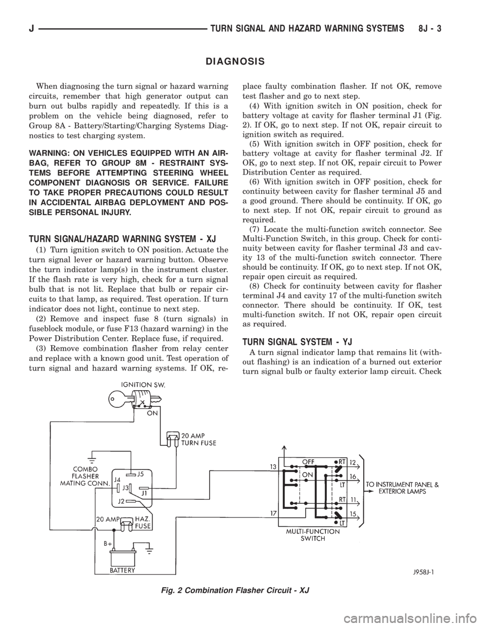
(4) With ignition switch in ON position, check for
battery voltage at cavity for flasher terminal J1 (Fig.
2). If OK, go to next step. If not OK, repair circuit to
ignition switch as required.
(5) With ignition switch in OFF position, check for
battery voltage at cavity for flasher terminal J2. If
OK, go to next step. If not OK, repair circuit to Power
Distribution Center as required.
(6) With ignition switch in OFF position, check for
continuity between cavity for flasher terminal J5 and
a good ground. There should be continuity. If OK, go
to next step. If not OK, repair circuit to ground as
required.
(7) Locate the multi-function switch connector. See
Multi-Function Switch, in this group. Check for conti-
nuity between cavity for flasher terminal J3 and cav-
ity 13 of the multi-function switch connector. There
should be continuity. If OK, go to next step. If not OK,
repair open circuit as required.
(8) Check for continuity between cavity for flasher
terminal J4 and cavity 17 of the multi-function switch
connector. There should be continuity. If OK, test
multi-function switch. If not OK, repair open circuit
as required.
TURN SIGNAL SYSTEM - YJ
A turn signal indicator lamp that remains lit (with-
out flashing) is an indication of a burned out exterior
turn signal bulb or faulty exterior lamp circuit. Check
Fig. 2 Combination Flasher Circuit - XJ
JTURN SIGNAL AND HAZARD WARNING SYSTEMS 8J - 3
Page 431 of 2158
SERVICE PROCEDURES
WARNING: ON VEHICLES EQUIPPED WITH AN AIRBAG,
REFER TO GROUP 8M - RESTRAINT SYSTEMS BEFORE
ATTEMPTING STEERING WHEEL COMPONENT DIAGNO-
SIS OR SERVICE. FAILURE TO TAKE PROPER PRECAU-
TIONS COULD RESULT IN ACCIDENTAL AIRBAG DE-
PLOYMENT AND POSSIBLE PERSONAL INJURY.
MULTI-FUNCTION SWITCH REMOVE/INSTALL - XJ
(1) Disconnect battery negative cable.
(2) Remove tilt lever (if equipped).
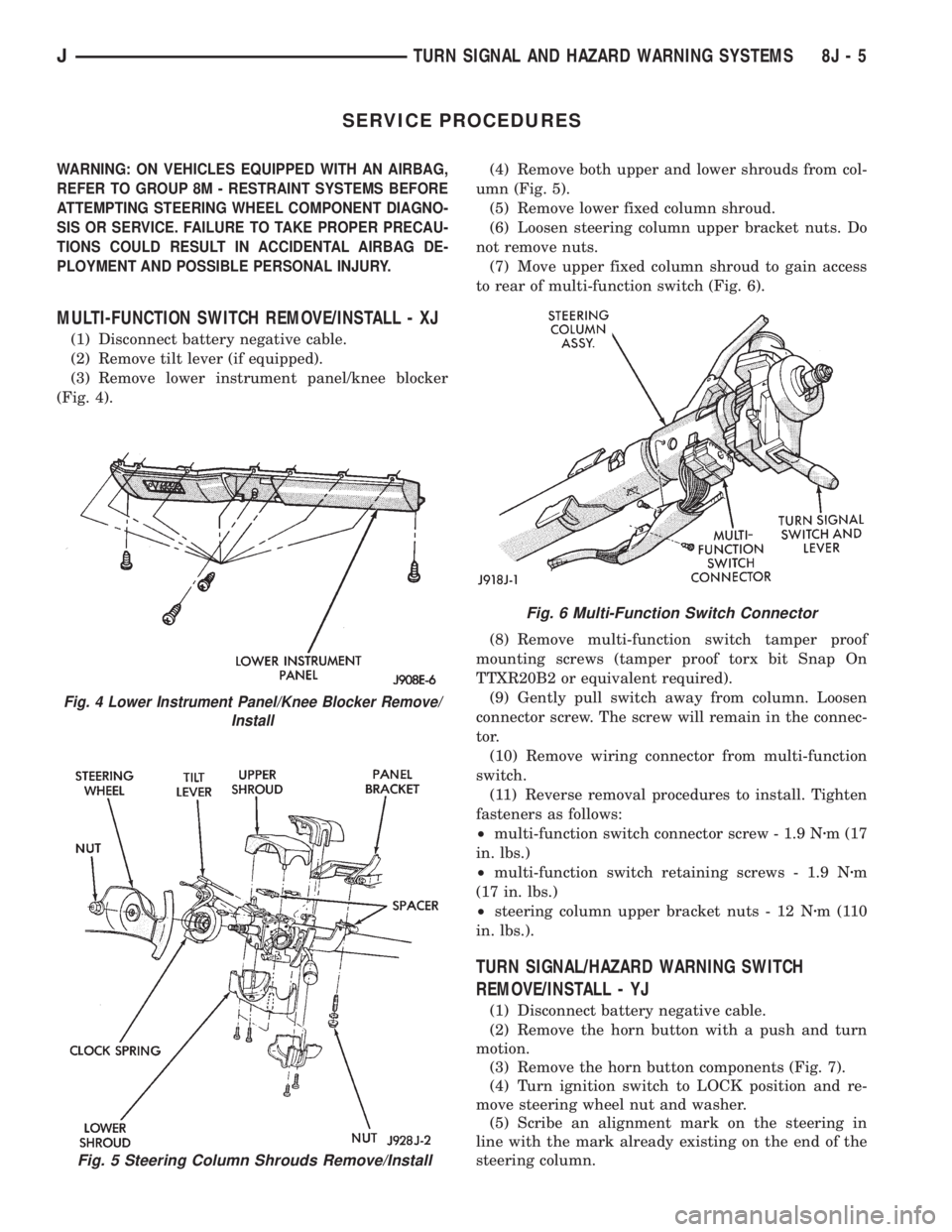
(3) Remove lower instrument panel/knee blocker
(Fig. 4).(4) Remove both upper and lower shrouds from col-
umn (Fig. 5).
(5) Remove lower fixed column shroud.
(6) Loosen steering column upper bracket nuts. Do
not remove nuts.
(7) Move upper fixed column shroud to gain access
to rear of multi-function switch (Fig. 6).
(8) Remove multi-function switch tamper proof
mounting screws (tamper proof torx bit Snap On
TTXR20B2 or equivalent required).
(9) Gently pull switch away from column. Loosen
connector screw. The screw will remain in the connec-
tor.
(10) Remove wiring connector from multi-function
switch.
(11) Reverse removal procedures to install. Tighten
fasteners as follows:
²multi-function switch connector screw - 1.9 Nzm (17
in. lbs.)
²multi-function switch retaining screws - 1.9 Nzm
(17 in. lbs.)
²steering column upper bracket nuts - 12 Nzm(110
in. lbs.).
TURN SIGNAL/HAZARD WARNING SWITCH
REMOVE/INSTALL - YJ
(1) Disconnect battery negative cable.
(2) Remove the horn button with a push and turn
motion.
(3) Remove the horn button components (Fig. 7).
(4) Turn ignition switch to LOCK position and re-
move steering wheel nut and washer.
(5) Scribe an alignment mark on the steering in
line with the mark already existing on the end of the
steering column.
Fig. 5 Steering Column Shrouds Remove/Install
Fig. 4 Lower Instrument Panel/Knee Blocker Remove/
Install
Fig. 6 Multi-Function Switch Connector
JTURN SIGNAL AND HAZARD WARNING SYSTEMS 8J - 5
Page 432 of 2158
(6) Remove vibration damper from the steering col-
umn hub, if equipped.
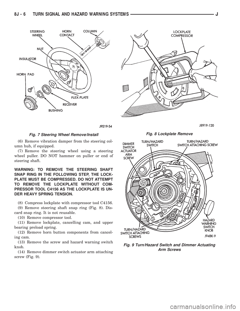
(7) Remove the steering wheel using a steering
wheel puller. DO NOT hammer on puller or end of
steering shaft.
WARNING: TO REMOVE THE STEERING SHAFT
SNAP RING IN THE FOLLOWING STEP, THE LOCK-
PLATE MUST BE COMPRESSED. DO NOT ATTEMPT
TO REMOVE THE LOCKPLATE WITHOUT COM-
PRESSOR TOOL C4156 AS THE LOCKPLATE IS UN-
DER HEAVY SPRING TENSION.
(8) Compress lockplate with compressor tool C4156.
(9) Remove steering shaft snap ring (Fig. 8). Dis-
card snap ring. It is not reusable.
(10) Remove compressor tool.
(11) Remove lockplate, cancelling cam, and upper
bearing preload spring.
(12) Remove horn button components from cancel-
ing cam.
(13) Remove the screw and hazard warning switch
knob.
(14) Remove dimmer switch actuator arm attaching
screw (Fig. 9).
Fig. 7 Steering Wheel Remove/InstallFig. 8 Lockplate Remove
Fig. 9 Turn/Hazard Switch and Dimmer Actuating
Arm Screws
8J - 6 TURN SIGNAL AND HAZARD WARNING SYSTEMSJ
Page 433 of 2158
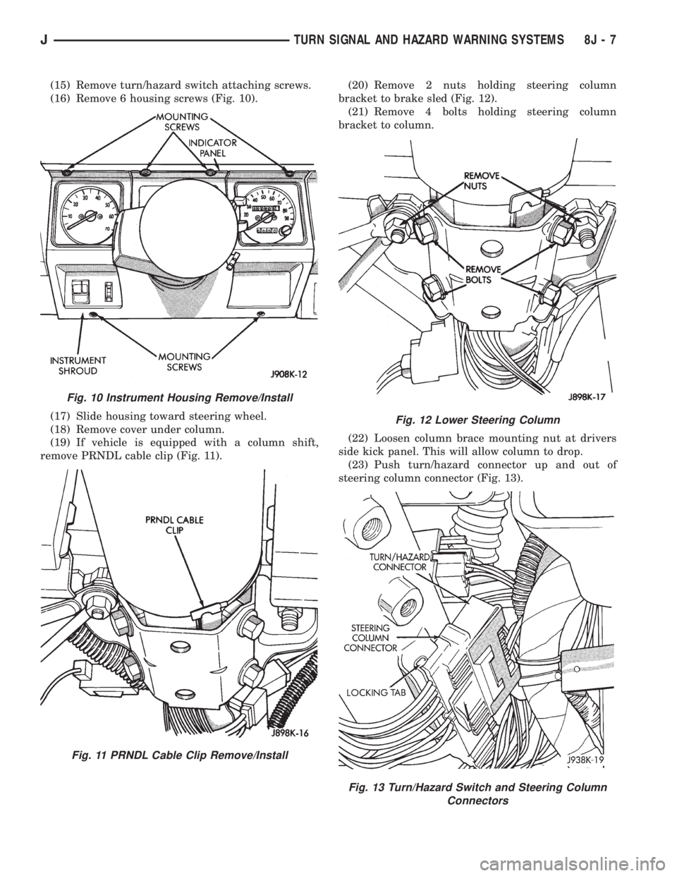
(15) Remove turn/hazard switch attaching screws.
(16) Remove 6 housing screws (Fig. 10).
(17) Slide housing toward steering wheel.
(18) Remove cover under column.
(19) If vehicle is equipped with a column shift,
remove PRNDL cable clip (Fig. 11).(20) Remove 2 nuts holding steering column
bracket to brake sled (Fig. 12).
(21) Remove 4 bolts holding steering column
bracket to column.
(22) Loosen column brace mounting nut at drivers
side kick panel. This will allow column to drop.
(23) Push turn/hazard connector up and out of
steering column connector (Fig. 13).
Fig. 10 Instrument Housing Remove/Install
Fig. 11 PRNDL Cable Clip Remove/Install
Fig. 12 Lower Steering Column
Fig. 13 Turn/Hazard Switch and Steering Column
Connectors
JTURN SIGNAL AND HAZARD WARNING SYSTEMS 8J - 7
Page 436 of 2158

The two pivot cranks are joined by a connecting link,
and a drive link connects the motor crank to the drive
link near the left pivot. Pressed-in plastic bushings in
the ends of the links can be replaced if worn or dam-
aged.
WINDSHIELD WIPER MOTOR
The two-speed permanent magnet wiper motor has
an integral transmission and park switch. The motor
is mounted to the engine side of the cowl panel with
a reinforcement/stud plate and a rubber-isolated
mounting bracket. The wiper motor output shaft
passes through the cowl panel into the cowl plenum
area, where a crank arm attached to the output shaft
drives the wiper drive link.
Wiper speed is controlled by current flow to the ap-
propriate set of brushes. The wiper motor completes
its wipe cycle when the switch is turned OFF, and
parks the blades in the lowest portion of the wipe
pattern. The wiper motor assembly can not be re-
paired. If faulty, the entire motor assembly must be
replaced. The crank arm, mounting bracket, and re-
inforcement/stud plate are available for service.
LIFTGATE WIPER MOTOR
The liftgate wiper motor contains integral elec-
tronic controls and a transmission to provide three
operating modes:
²intermittent wipe with a fixed 5 to 8 second delay
between wipes
²constant wipe that operates when the liftgate
washer is operated
²a park mode that runs the motor until the wiper
blade reaches the park position after the liftgate
wiper switch or ignition switch is turned OFF.
The liftgate wiper motor can not be repaired. If
faulty, the entire assembly must be replaced.
WINDSHIELD WIPER/WASHER SWITCH
Controls for the windshield wiper and washer sys-
tems are contained in the multi-function switch con-
trol lever. The multi-function switch is mounted on
the left side of the steering column between the
steering wheel and the instrument panel. This switch
also controls many other functions. The multi-func-
tion switch can not be repaired. If any function of the
switch is faulty, the entire switch must be replaced.
LIFTGATE WIPER/WASHER SWITCH
The single two-function switch on the instrument
panel right of the steering column controls the lift-
gate wiper and washer functions. The rocker-type
switch features a detent in the WIPE position, but
only momentary contact in the WASH position. Both
the liftgate wiper and liftgate washer motors will op-
erate continuously for as long as the switch is held in
the WASH position. The switch can not be repaired;
if faulty, it must be replaced.
INTERMITTENT WIPE MODULE
In addition to low and high speed, the optional inter-
mittent wipe system has a delay mode. The delay mode
has a range of 2 to 15 seconds. The length of the delay
is selected with a variable resistor in the wiper (multi-
function) switch and is accomplished by electronic cir-
cuitry within the intermittent wipe module. If the
washer knob is depressed while the wiper (multi-func-
tion) switch is in the OFF position, the intermittent
wipe module will operate the wiper motor for approxi-
mately 2 wipes and automatically turn the motor off.
The intermittent wipe module is mounted to the
lower instrument panel, behind the knee blocker and
near the steering column with a hook and loop fas-
tener patch. The module can not be repaired.
WINDSHIELD WASHER NOZZLES
The two fluidic washer nozzles are riveted into
openings in the cowl grille panel below the wind-
shield and are not adjustable. Washer fluid is fed to
the nozzles through hoses clipped to the underside of
the cowl grille panel. The nozzles can not be repaired
and, if faulty, should be replaced.
LIFTGATE WASHER NOZZLE
The single liftgate washer nozzle snaps into place
on the liftgate wiper arm. Washer fluid is fed to the
nozzle from the washer reservoir in the engine com-
partment. A liftgate washer hose system is routed
through the body of the vehicle with the body wiring
harness from the reservoir to the liftgate. The fluid
passes through a nipple on the liftgate wiper motor
output shaft bezel to a hose clipped to the underside
of the wiper arm. The nozzle can not be repaired and,
if faulty, should be replaced.
WASHER RESERVOIR
The washer solvent reservoir is mounted to the left
front inner fender shield near the cowl panel. The
same reservoir is used for both the standard front
and optional liftgate washer systems. It also has a
provision for a low washer fluid level sensor. Refer to
Group 8E - Instrument Panel and Gauges for diagno-
sis and service of the sensor. The reservoir and filler
cap are available for service.
WASHER PUMPS
The washer pump and motor are press-fit into a
rubber grommet near the bottom of the washer res-
ervoir. Vehicles with the optional liftgate wiper/
washer system have two pumps installed in the
single reservoir. A permanently lubricated and sealed
motor is coupled to a rotor-type pump. Washer fluid
is gravity fed from the reservoir to the pump. The
pump then pressurizes the fluid and forces it through
the plumbing to the nozzles when the motor is ener-
gized. The pump and motor can not be repaired. If
faulty, the entire assembly must be replaced.
8K - 2 WIPER AND WASHER SYSTEMS - XJJ
Page 445 of 2158
The liftgate wiper motor can not be repaired. If
faulty, the entire assembly must be replaced.
WINDSHIELD WIPER/WASHER SWITCH
Controls for the windshield wiper and washer sys-
tems are contained in the turn signal switch lever.
The turn signal switch lever is mounted on the left
side of the steering column between the steering
wheel and the instrument panel. The wiper/washer
switch can not be repaired. If any function of the
switch is faulty, the entire switch must be replaced.
LIFTGATE WIPER/WASHER SWITCH
The single two-function switch on the instrument
panel right of the steering column controls the lift-
gate wiper and washer functions. The rocker-type
switch features a detent in the WIPE position, but
only momentary contact in the WASH position. Both
the liftgate wiper and liftgate washer motors will op-
erate continuously for as long as the switch is held in
the WASH position. The switch can not be repaired;
if faulty, it must be replaced.
INTERMITTENT WIPE MODULE
In addition to low and high speed, the optional in-
termittent wipe system has a delay mode. The delay
mode has a range of 2 to 15 seconds. The length of
the delay is selected with a variable resistor in the
wiper switch and is accomplished by electronic cir-
cuitry within the intermittent wipe module. If the
washer knob is depressed while the wiper switch is
in the OFF position, the intermittent wipe module
will operate the wiper motor for approximately 2
wipes and automatically turn the motor off.
The intermittent wipe module is mounted to a
bracket behind the lower instrument panel, near the
steering column with a hook and loop fastener patch.
The module can not be repaired.
WINDSHIELD WASHER NOZZLES
The two fluidic washer nozzles are screwed into
openings in the cowl panel below the windshield and
are not adjustable. Washer fluid is fed to the nozzles
through hoses underneath the cowl panel. The noz-
zles can not be repaired and, if faulty, should be re-
placed.
LIFTGATE WASHER NOZZLE
The single liftgate washer nozzle is installed
through the liftgate glass and secured with a nut on
the inside of the glass. Washer fluid is fed to the noz-
zle from the washer reservoir in the engine compart-
ment. A liftgate washer hose system is routed
through the body of the vehicle with the body wiring
harness from the reservoir to the liftgate. The nozzle
can not be repaired and, if faulty, should be replaced.
WASHER RESERVOIR
The washer solvent reservoir is mounted with a
bracket to the left front inner fender shield near the
cowl panel. The same reservoir is used for both the
standard front and optional liftgate washer systems.
The reservoir and filler cap are available for service.
WASHER PUMPS
The washer pump and motor are press-fit into a
rubber grommet near the bottom of the washer res-
ervoir. Vehicles with the optional liftgate wiper/
washer system have two pumps installed in the
single reservoir. A permanently lubricated and sealed
motor is coupled to a rotor-type pump. Washer fluid
is gravity fed from the reservoir to the pump. The
pump then pressurizes the fluid and forces it through
the plumbing to the nozzles when the motor is ener-
gized. The pump and motor can not be repaired. If
faulty, the entire assembly must be replaced.
JWIPER AND WASHER SYSTEMS - YJ 8K - 11
Page 454 of 2158
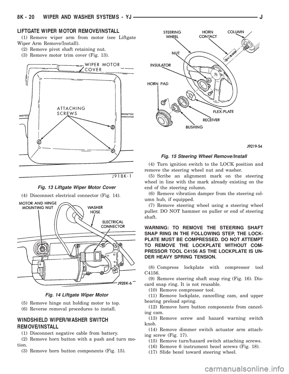
LIFTGATE WIPER MOTOR REMOVE/INSTALL
(1) Remove wiper arm from motor (see Liftgate
Wiper Arm Remove/Install).
(2) Remove pivot shaft retaining nut.
(3) Remove motor trim cover (Fig. 13).
(4) Disconnect electrical connector (Fig. 14).
(5) Remove hinge nut holding motor to top.
(6) Reverse removal procedures to install.
WINDSHIELD WIPER/WASHER SWITCH
REMOVE/INSTALL
(1) Disconnect negative cable from battery.
(2) Remove horn button with a push and turn mo-
tion.
(3) Remove horn button components (Fig. 15).(4) Turn ignition switch to the LOCK position and
remove the steering wheel nut and washer.
(5) Scribe an alignment mark on the steering
wheel in line with the mark already existing on the
end of the steering column.
(6) Remove vibration damper from the steering col-
umn hub, if equipped.
(7) Remove steering wheel using a steering wheel
puller. DO NOT hammer on puller or end of steering
shaft.
WARNING: TO REMOVE THE STEERING SHAFT
SNAP RING IN THE FOLLOWING STEP, THE LOCK-
PLATE MUST BE COMPRESSED. DO NOT ATTEMPT
TO REMOVE THE LOCKPLATE WITHOUT COM-
PRESSOR TOOL C4156 AS THE LOCKPLATE IS UN-
DER HEAVY SPRING TENSION.
(8) Compress lockplate with compressor tool
C4156.
(9) Remove steering shaft snap ring (Fig. 16). Dis-
card snap ring. It is not reusable.
(10) Remove compressor tool.
(11) Remove lockplate, cancelling cam, and upper
bearing preload spring.
(12) Remove horn button components from cancel-
ing cam.
(13) Remove screw and hazard warning switch
knob.
(14) Remove dimmer switch actuator arm attach-
ing screw (Fig. 17).
(15) Remove turn/hazard switch attaching screws.
(16) Remove 6 instrument bezel screws (Fig. 18).
(17) Slide bezel toward steering wheel.
Fig. 13 Liftgate Wiper Motor Cover
Fig. 14 Liftgate Wiper Motor
Fig. 15 Steering Wheel Remove/Install
8K - 20 WIPER AND WASHER SYSTEMS - YJJ
Page 458 of 2158
(36) Install a new switch and switch cover.
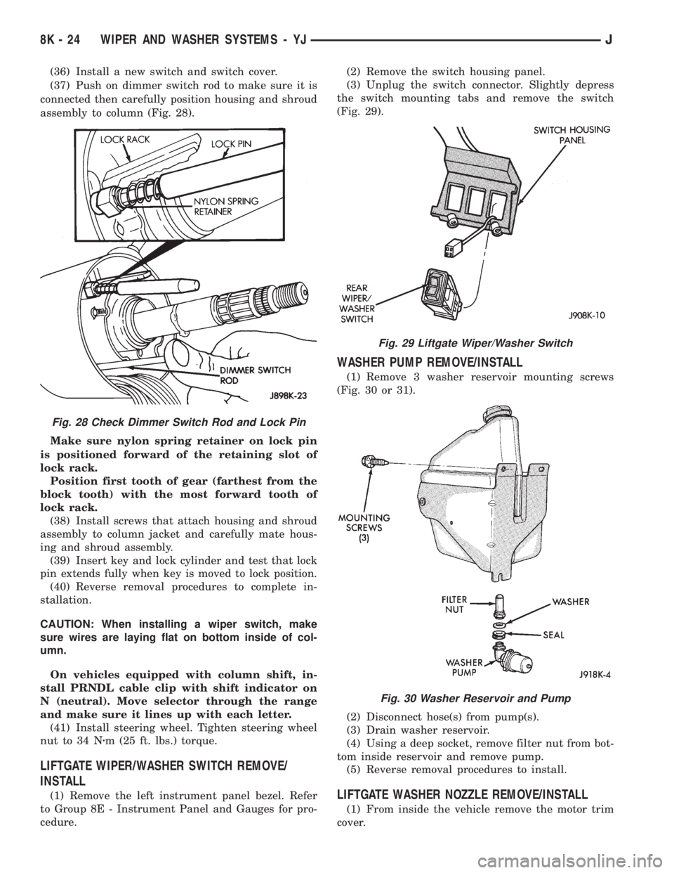
(37) Push on dimmer switch rod to make sure it is
connected then carefully position housing and shroud
assembly to column (Fig. 28).
Make sure nylon spring retainer on lock pin
is positioned forward of the retaining slot of
lock rack.
Position first tooth of gear (farthest from the
block tooth) with the most forward tooth of
lock rack.
(38) Install screws that attach housing and shroud
assembly to column jacket and carefully mate hous-
ing and shroud assembly.
(39) Insert key and lock cylinder and test that lock
pin extends fully when key is moved to lock position.
(40) Reverse removal procedures to complete in-
stallation.
CAUTION: When installing a wiper switch, make
sure wires are laying flat on bottom inside of col-
umn.
On vehicles equipped with column shift, in-
stall PRNDL cable clip with shift indicator on
N (neutral). Move selector through the range
and make sure it lines up with each letter.
(41) Install steering wheel. Tighten steering wheel
nut to 34 Nzm (25 ft. lbs.) torque.
LIFTGATE WIPER/WASHER SWITCH REMOVE/
INSTALL
(1) Remove the left instrument panel bezel. Refer
to Group 8E - Instrument Panel and Gauges for pro-
cedure.(2) Remove the switch housing panel.
(3) Unplug the switch connector. Slightly depress
the switch mounting tabs and remove the switch
(Fig. 29).
WASHER PUMP REMOVE/INSTALL
(1) Remove 3 washer reservoir mounting screws
(Fig. 30 or 31).
(2) Disconnect hose(s) from pump(s).
(3) Drain washer reservoir.
(4) Using a deep socket, remove filter nut from bot-
tom inside reservoir and remove pump.
(5) Reverse removal procedures to install.
LIFTGATE WASHER NOZZLE REMOVE/INSTALL
(1) From inside the vehicle remove the motor trim
cover.
Fig. 28 Check Dimmer Switch Rod and Lock Pin
Fig. 29 Liftgate Wiper/Washer Switch
Fig. 30 Washer Reservoir and Pump
8K - 24 WIPER AND WASHER SYSTEMS - YJJ