1995 JEEP YJ steering wheel
[x] Cancel search: steering wheelPage 1485 of 2158
STEERING
CONTENTS
page page
GENERAL INFORMATION.................. 1
GENERAL INFORMATION................. 48
MANUAL STEERING GEAR................ 37
POWER STEERING PUMP................. 11
POWER STEERING SYSTEM DIAGNOSIS...... 3
RECIRCULATING BALL POWER STEERING
GEAR............................... 21STEERING COLUMN GENERAL SERVICEÐXJ . 47
STEERING COLUMNÐYJ................. 58
STEERING LINKAGEÐXJ................. 16
STEERING LINKAGEÐYJ................. 19
STEERING RHD......................... 74
TORQUE SPECIFICATIONS................ 78
GENERAL INFORMATION
STEERING SYSTEM COMPONENTS
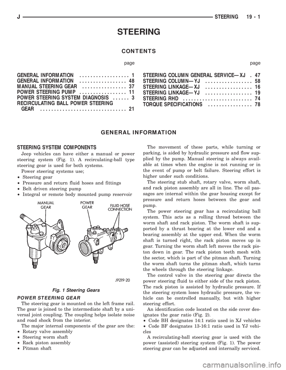
Jeep vehicles can have either a manual or power
steering system (Fig. 1). A recirculating-ball type
steering gear is used for both systems.
Power steering systems use;
²Steering gear
²Pressure and return fluid hoses and fittings
²Belt driven steering pump
²Integral or remote body mounted pump reservoir
POWER STEERING GEAR
The steering gear is mounted on the left frame rail.
The gear is joined to the intermediate shaft by a uni-
versal joint coupling. The coupling helps isolate noise
and road shock from the interior.
The major internal components of the gear are the:
²Rotary valve assembly
²Steering worm shaft
²Rack piston assembly
²Pitman shaftThe movement of these parts, while turning or
parking, is aided by hydraulic pressure and flow sup-
plied by the pump. Manual steering is always avail-
able at times when the engine is not running or in
the event of pump or belt failure. Steering effort is
higher under such conditions.
The steering stub shaft, rotary valve, worm shaft,
and rack piston assembly are all in line. The oil pas-
sages are internal within the gear housing except for
pressure and return hoses between the gear and
pump.
The power steering gear has a recirculating ball
system. This acts as a rolling thread between the
worm shaft and rack piston. The worm shaft is sup-
ported by a thrust bearing at the lower end and a
bearing assembly at the upper end. When the worm
shaft is turned right, the rack piston moves up in
gear. Turning the worm shaft left moves the rack pis-
ton down in gear. The rack piston teeth mesh with
the sector, which is part of the pitman shaft. Turning
the worm shaft turns the pitman shaft, which turns
the wheels through the steering linkage.
The control valve in the steering gear directs the
power steering fluid to either side of the rack piston.
The rack piston is assisted by hydraulic pressure. If
the steering system loses hydraulic pressure, the ve-
hicle can be controlled manually, but with higher
steering effort.
An identification code located on the side cover des-
ignates the gear ratio (Fig. 2).
²Code BH designates 14:1 ratio used in XJ vehicles
²Code BF designates 13-16:1 ratio used in YJ vehi-
cles
A recirculating-ball steering gear is used with the
power (assisted) steering system (Fig. 1). The power
steering gear can be adjusted and internally serviced.
Fig. 1 Steering Gears
JSTEERING 19 - 1
Page 1487 of 2158
POWER STEERING SYSTEM DIAGNOSIS
PUMP PRESSURE TEST
(1) Check belt tension and adjust as necessary.
(2) Disconnect high pressure hose at gear or pump.
Use a container for dripping fluid.
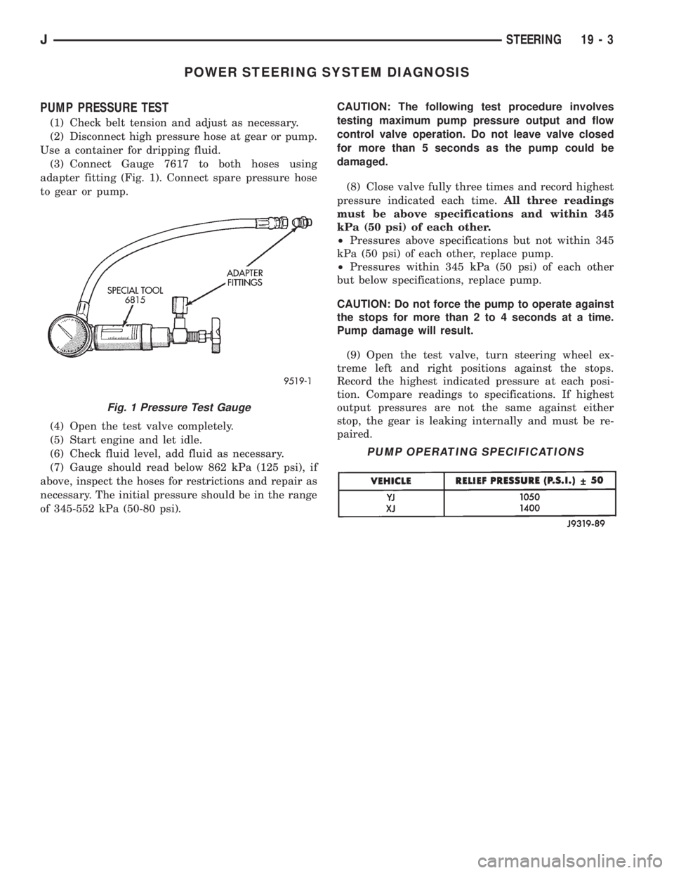
(3) Connect Gauge 7617 to both hoses using
adapter fitting (Fig. 1). Connect spare pressure hose
to gear or pump.
(4) Open the test valve completely.
(5) Start engine and let idle.
(6) Check fluid level, add fluid as necessary.
(7) Gauge should read below 862 kPa (125 psi), if
above, inspect the hoses for restrictions and repair as
necessary. The initial pressure should be in the range
of 345-552 kPa (50-80 psi).CAUTION: The following test procedure involves
testing maximum pump pressure output and flow
control valve operation. Do not leave valve closed
for more than 5 seconds as the pump could be
damaged.
(8) Close valve fully three times and record highest
pressure indicated each time.All three readings
must be above specifications and within 345
kPa (50 psi) of each other.
²Pressures above specifications but not within 345
kPa (50 psi) of each other, replace pump.
²Pressures within 345 kPa (50 psi) of each other
but below specifications, replace pump.
CAUTION: Do not force the pump to operate against
the stops for more than 2 to 4 seconds at a time.
Pump damage will result.
(9) Open the test valve, turn steering wheel ex-
treme left and right positions against the stops.
Record the highest indicated pressure at each posi-
tion. Compare readings to specifications. If highest
output pressures are not the same against either
stop, the gear is leaking internally and must be re-
paired.
Fig. 1 Pressure Test Gauge
PUMP OPERATING SPECIFICATIONS
JSTEERING 19 - 3
Page 1499 of 2158
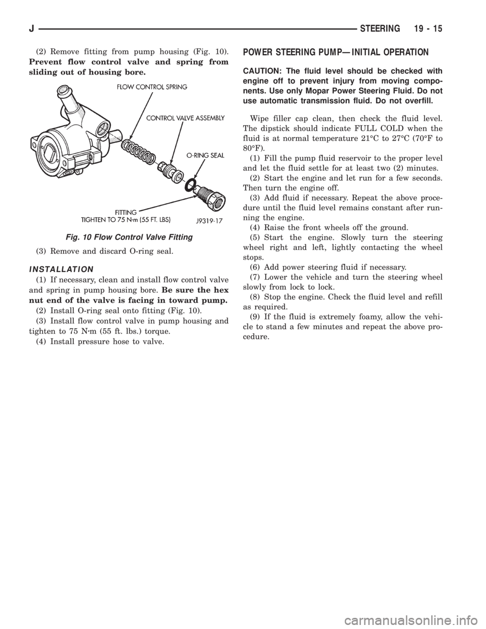
(2) Remove fitting from pump housing (Fig. 10).
Prevent flow control valve and spring from
sliding out of housing bore.
(3) Remove and discard O-ring seal.
INSTALLATION
(1) If necessary, clean and install flow control valve
and spring in pump housing bore.Be sure the hex
nut end of the valve is facing in toward pump.
(2) Install O-ring seal onto fitting (Fig. 10).
(3) Install flow control valve in pump housing and
tighten to 75 Nzm (55 ft. lbs.) torque.
(4) Install pressure hose to valve.
POWER STEERING PUMPÐINITIAL OPERATION
CAUTION: The fluid level should be checked with
engine off to prevent injury from moving compo-
nents. Use only Mopar Power Steering Fluid. Do not
use automatic transmission fluid. Do not overfill.
Wipe filler cap clean, then check the fluid level.
The dipstick should indicate FULL COLD when the
fluid is at normal temperature 21ÉC to 27ÉC (70ÉF to
80ÉF).
(1) Fill the pump fluid reservoir to the proper level
and let the fluid settle for at least two (2) minutes.
(2) Start the engine and let run for a few seconds.
Then turn the engine off.
(3) Add fluid if necessary. Repeat the above proce-
dure until the fluid level remains constant after run-
ning the engine.
(4) Raise the front wheels off the ground.
(5) Start the engine. Slowly turn the steering
wheel right and left, lightly contacting the wheel
stops.
(6) Add power steering fluid if necessary.
(7) Lower the vehicle and turn the steering wheel
slowly from lock to lock.
(8) Stop the engine. Check the fluid level and refill
as required.
(9) If the fluid is extremely foamy, allow the vehi-
cle to stand a few minutes and repeat the above pro-
cedure.
Fig. 10 Flow Control Valve Fitting
JSTEERING 19 - 15
Page 1500 of 2158
STEERING LINKAGEÐXJ
INDEX
page page
Drag Link............................... 16
Pitman Arm.............................. 17
Service Information........................ 16Steering Damper.......................... 17
TieRod ................................ 16
SERVICE INFORMATION
The steering linkage consists of a pitman arm, drag
link, tie rod, and steering damper. Adjustment
sleeves are used on the tie rod and drag link for toe
and steering wheel alignment.
Refer to Group 2, Front Suspension and Axle for
additional information.
The tie-rod end ball stud seals should be inspected
during all oil changes.
A damaged ball stud seal requires removal of the
seal. Inspect the tie-rod end ball stud at the throat
opening. Check for lubricant loss, contamination, ball
stud wear or corrosion. If these conditions exist, re-
place the tie-rod. A replacement seal can be installed
if lubricant is in good condition. Otherwise, a com-
plete replacement ball stud end should be installed.
Lubricate the tie-rod end with MOPARtMulti-Mile-
age Lubricant, or equivalent product.
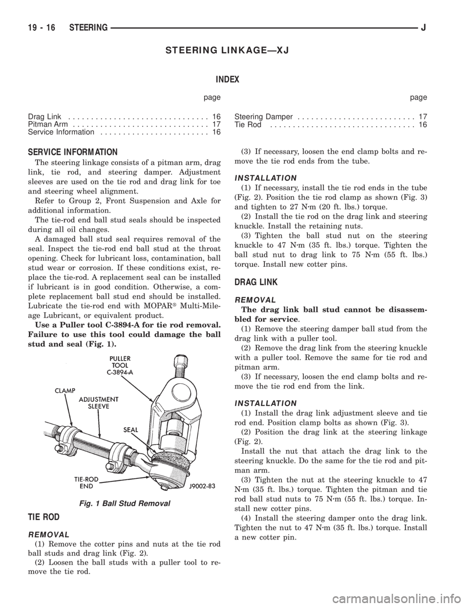
Use a Puller tool C-3894-A for tie rod removal.
Failure to use this tool could damage the ball
stud and seal (Fig. 1).
TIE ROD
REMOVAL
(1) Remove the cotter pins and nuts at the tie rod
ball studs and drag link (Fig. 2).
(2) Loosen the ball studs with a puller tool to re-
move the tie rod.(3) If necessary, loosen the end clamp bolts and re-
move the tie rod ends from the tube.
INSTALLATION
(1) If necessary, install the tie rod ends in the tube
(Fig. 2). Position the tie rod clamp as shown (Fig. 3)
and tighten to 27 Nzm (20 ft. lbs.) torque.
(2) Install the tie rod on the drag link and steering
knuckle. Install the retaining nuts.
(3) Tighten the ball stud nut on the steering
knuckle to 47 Nzm (35 ft. lbs.) torque. Tighten the
ball stud nut to drag link to 75 Nzm (55 ft. lbs.)
torque. Install new cotter pins.
DRAG LINK
REMOVAL
The drag link ball stud cannot be disassem-
bled for service.
(1) Remove the steering damper ball stud from the
drag link with a puller tool.
(2) Remove the drag link from the steering knuckle
with a puller tool. Remove the same for tie rod and
pitman arm.
(3) If necessary, loosen the end clamp bolts and re-
move the tie rod end from the link.
INSTALLATION
(1) Install the drag link adjustment sleeve and tie
rod end. Position clamp bolts as shown (Fig. 3).
(2) Position the drag link at the steering linkage
(Fig. 2).
Install the nut that attach the drag link to the
steering knuckle. Do the same for the tie rod and pit-
man arm.
(3) Tighten the nut at the steering knuckle to 47
Nzm (35 ft. lbs.) torque. Tighten the pitman and tie
rod ball stud nuts to 75 Nzm (55 ft. lbs.) torque. In-
stall new cotter pins.
(4) Install the steering damper onto the drag link.
Tighten the nut to 47 Nzm (35 ft. lbs.) torque. Install
a new cotter pin.
Fig. 1 Ball Stud Removal
19 - 16 STEERINGJ
Page 1501 of 2158
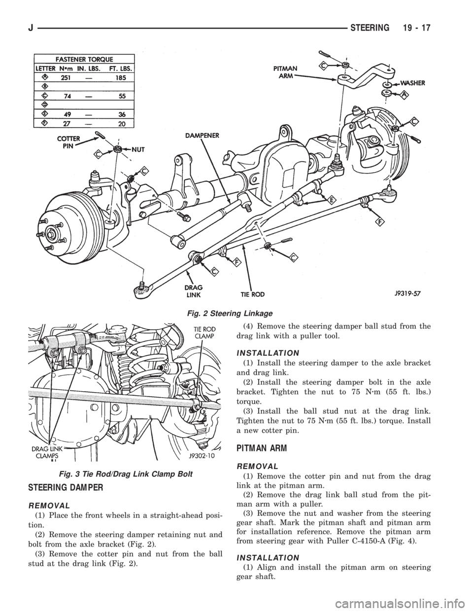
STEERING DAMPER
REMOVAL
(1) Place the front wheels in a straight-ahead posi-
tion.
(2) Remove the steering damper retaining nut and
bolt from the axle bracket (Fig. 2).
(3) Remove the cotter pin and nut from the ball
stud at the drag link (Fig. 2).(4) Remove the steering damper ball stud from the
drag link with a puller tool.
INSTALLATION
(1) Install the steering damper to the axle bracket
and drag link.
(2) Install the steering damper bolt in the axle
bracket. Tighten the nut to 75 Nzm (55 ft. lbs.)
torque.
(3) Install the ball stud nut at the drag link.
Tighten the nut to 75 Nzm (55 ft. lbs.) torque. Install
a new cotter pin.
PITMAN ARM
REMOVAL
(1) Remove the cotter pin and nut from the drag
link at the pitman arm.
(2) Remove the drag link ball stud from the pit-
man arm with a puller.
(3) Remove the nut and washer from the steering
gear shaft. Mark the pitman shaft and pitman arm
for installation reference. Remove the pitman arm
from steering gear with Puller C-4150-A (Fig. 4).
INSTALLATION
(1) Align and install the pitman arm on steering
gear shaft.
Fig. 2 Steering Linkage
Fig. 3 Tie Rod/Drag Link Clamp Bolt
JSTEERING 19 - 17
Page 1503 of 2158
STEERING LINKAGEÐYJ
INDEX
page page
Drag Link............................... 20
Pitman Arm.............................. 20
Service Information........................ 19Steering Damper.......................... 20
TieRod ................................ 19
SERVICE INFORMATION
The steering linkage consists of a pitman arm, drag
link, tie rod, and steering damper. Adjustment
sleeves are used on the tie rod and drag link for toe
and steering wheel alignment.
Refer to Group 2, Front Suspension and Axle for
additional information.The tie-rod end ball stud seals should be inspected
during all oil changes.
A damaged ball stud seal requires removal of the
seal. Inspect the tie-rod end ball stud at the throat
opening. Check for lubricant loss, contamination, ball
stud wear or corrosion. If these conditions exist, re-
place the tie-rod. A replacement seal can be installed
if lubricant is in good condition. Otherwise, a com-
plete replacement ball stud end should be installed.
Lubricate the tie-rod end with MOPARtMulti-Mile-
age Lubricant, or equivalent product.
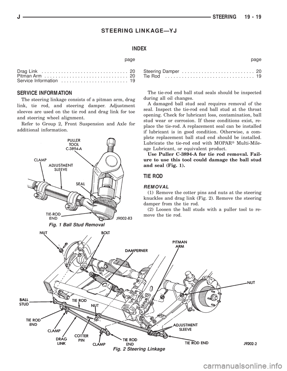
Use Puller C-3894-A for tie rod removal. Fail-
ure to use this tool could damage the ball stud
and seal (Fig. 1).
TIE ROD
REMOVAL
(1) Remove the cotter pins and nuts at the steering
knuckles and drag link (Fig. 2). Remove the steering
damper from the tie rod.
(2) Loosen the ball studs with a puller tool to re-
move the tie rod.
Fig. 1 Ball Stud Removal
Fig. 2 Steering Linkage
JSTEERING 19 - 19
Page 1504 of 2158
(3) If necessary, loosen the end clamp bolts and re-
move the tie rod end from the tube.
INSTALLATION
(1) If necessary, install the tie rod end in the tube
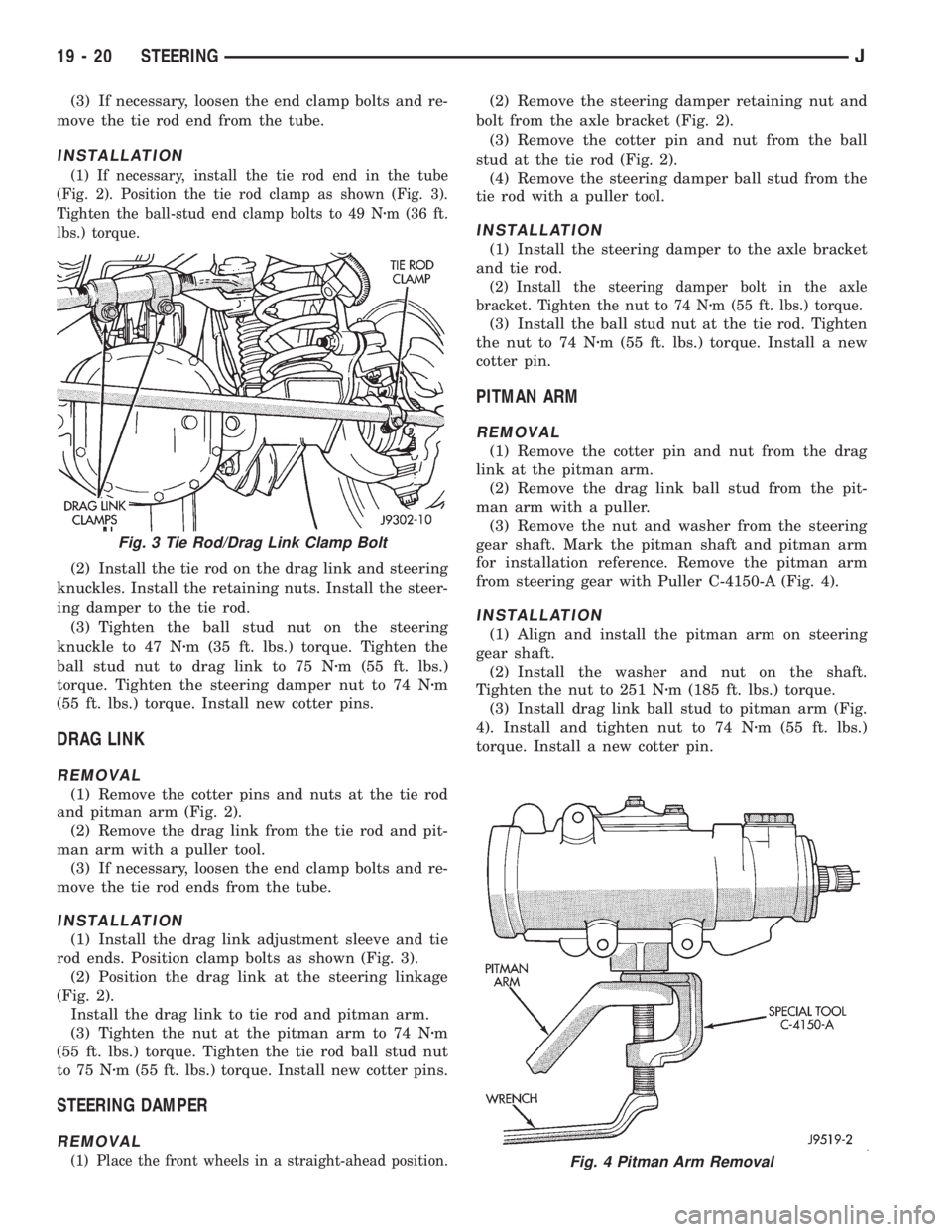
(Fig. 2). Position the tie rod clamp as shown (Fig. 3).
Tighten the ball-stud end clamp bolts to 49 Nzm (36 ft.
lbs.) torque.
(2) Install the tie rod on the drag link and steering
knuckles. Install the retaining nuts. Install the steer-
ing damper to the tie rod.
(3) Tighten the ball stud nut on the steering
knuckle to 47 Nzm (35 ft. lbs.) torque. Tighten the
ball stud nut to drag link to 75 Nzm (55 ft. lbs.)
torque. Tighten the steering damper nut to 74 Nzm
(55 ft. lbs.) torque. Install new cotter pins.
DRAG LINK
REMOVAL
(1) Remove the cotter pins and nuts at the tie rod
and pitman arm (Fig. 2).
(2) Remove the drag link from the tie rod and pit-
man arm with a puller tool.
(3) If necessary, loosen the end clamp bolts and re-
move the tie rod ends from the tube.
INSTALLATION
(1) Install the drag link adjustment sleeve and tie
rod ends. Position clamp bolts as shown (Fig. 3).
(2) Position the drag link at the steering linkage
(Fig. 2).
Install the drag link to tie rod and pitman arm.
(3) Tighten the nut at the pitman arm to 74 Nzm
(55 ft. lbs.) torque. Tighten the tie rod ball stud nut
to 75 Nzm (55 ft. lbs.) torque. Install new cotter pins.
STEERING DAMPER
REMOVAL
(1) Place the front wheels in a straight-ahead position.
(2) Remove the steering damper retaining nut and
bolt from the axle bracket (Fig. 2).
(3) Remove the cotter pin and nut from the ball
stud at the tie rod (Fig. 2).
(4) Remove the steering damper ball stud from the
tie rod with a puller tool.
INSTALLATION
(1) Install the steering damper to the axle bracket
and tie rod.
(2) Install the steering damper bolt in the axle
bracket. Tighten the nut to 74 Nzm (55 ft. lbs.) torque.
(3) Install the ball stud nut at the tie rod. Tighten
the nut to 74 Nzm (55 ft. lbs.) torque. Install a new
cotter pin.
PITMAN ARM
REMOVAL
(1) Remove the cotter pin and nut from the drag
link at the pitman arm.
(2) Remove the drag link ball stud from the pit-
man arm with a puller.
(3) Remove the nut and washer from the steering
gear shaft. Mark the pitman shaft and pitman arm
for installation reference. Remove the pitman arm
from steering gear with Puller C-4150-A (Fig. 4).
INSTALLATION
(1) Align and install the pitman arm on steering
gear shaft.
(2) Install the washer and nut on the shaft.
Tighten the nut to 251 Nzm (185 ft. lbs.) torque.
(3) Install drag link ball stud to pitman arm (Fig.
4). Install and tighten nut to 74 Nzm (55 ft. lbs.)
torque. Install a new cotter pin.
Fig. 4 Pitman Arm Removal
Fig. 3 Tie Rod/Drag Link Clamp Bolt
19 - 20 STEERINGJ
Page 1507 of 2158
PITMAN SHAFT SEALSÐIN CAR REPLACEMENT
REMOVAL
(1) Remove pitman arm from gear. Refer to Pitman
Arm Removal in Steering Linkage.
(2) Clean exposed end of pitman shaft and hous-
ing. Use a wire brush to clean the shaft splines.
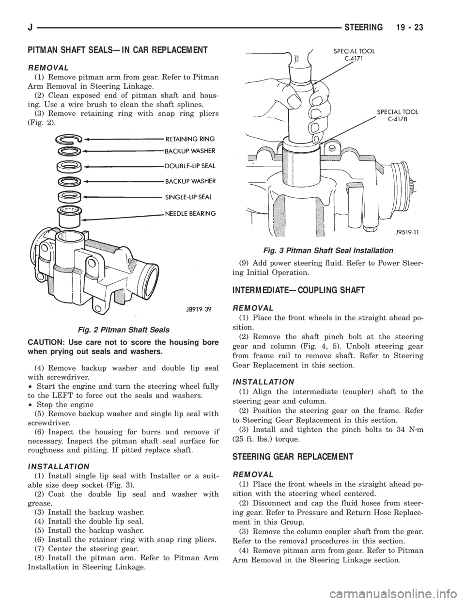
(3) Remove retaining ring with snap ring pliers
(Fig. 2).
CAUTION: Use care not to score the housing bore
when prying out seals and washers.
(4) Remove backup washer and double lip seal
with screwdriver.
²Start the engine and turn the steering wheel fully
to the LEFT to force out the seals and washers.
²Stop the engine
(5) Remove backup washer and single lip seal with
screwdriver.
(6) Inspect the housing for burrs and remove if
necessary. Inspect the pitman shaft seal surface for
roughness and pitting. If pitted replace shaft.
INSTALLATION
(1) Install single lip seal with Installer or a suit-
able size deep socket (Fig. 3).
(2) Coat the double lip seal and washer with
grease.
(3) Install the backup washer.
(4) Install the double lip seal.
(5) Install the backup washer.
(6) Install the retainer ring with snap ring pliers.
(7) Center the steering gear.
(8) Install the pitman arm. Refer to Pitman Arm
Installation in Steering Linkage.(9) Add power steering fluid. Refer to Power Steer-
ing Initial Operation.
INTERMEDIATEÐCOUPLING SHAFT
REMOVAL
(1) Place the front wheels in the straight ahead po-
sition.
(2) Remove the shaft pinch bolt at the steering
gear and column (Fig. 4, 5). Unbolt steering gear
from frame rail to remove shaft. Refer to Steering
Gear Replacement in this section.
INSTALLATION
(1) Align the intermediate (coupler) shaft to the
steering gear and column.
(2) Position the steering gear on the frame. Refer
to Steering Gear Replacement in this section.
(3) Install and tighten the pinch bolts to 34 Nzm
(25 ft. lbs.) torque.
STEERING GEAR REPLACEMENT
REMOVAL
(1) Place the front wheels in the straight ahead po-
sition with the steering wheel centered.
(2) Disconnect and cap the fluid hoses from steer-
ing gear. Refer to Pressure and Return Hose Replace-
ment in this Group.
(3) Remove the column coupler shaft from the gear.
Refer to the removal procedures in this section.
(4) Remove pitman arm from gear. Refer to Pitman
Arm Removal in the Steering Linkage section.
Fig. 2 Pitman Shaft Seals
Fig. 3 Pitman Shaft Seal Installation
JSTEERING 19 - 23