1995 JEEP YJ steering wheel
[x] Cancel search: steering wheelPage 354 of 2158

spring loaded to release when the key is released.
The maximum voltage drop between any two con-
nected terminals should not exceed 12.5 millivolts
per amp. For example: If a 10 amp load is drawn
through the switch, maximum voltage drop should be
10 x 0.0125 or 0.125 volt.
INSTALLATION/ADJUSTMENT
(1) Place the key lock switch in the ACCESSORY
position.
(2) Place the slider bar (in the ignition switch)
(Fig. 12) into the ACCESSORY detent position.
(3) Connect the wiring to the switch as follows: In-
stall the non-black (colored) connector first and then
the black (colored) connector to the ignition switch.
One connector will interlock the other connector.
(4) Slip the remote actuator rod into the access
hole on the switch (Fig. 12). Install the switch to the
steering column. Be careful not to move the slider
bar (on the switch) out of the ACCESSORY detent
position. Remove the ignition switch actuator rod se-
curing-tape from steering column.
(5) Install the two ignition switch-to-steering col-
umn screws finger tight.Do not tighten screws at
this time.
(6) Adjust ignition switch as follows:
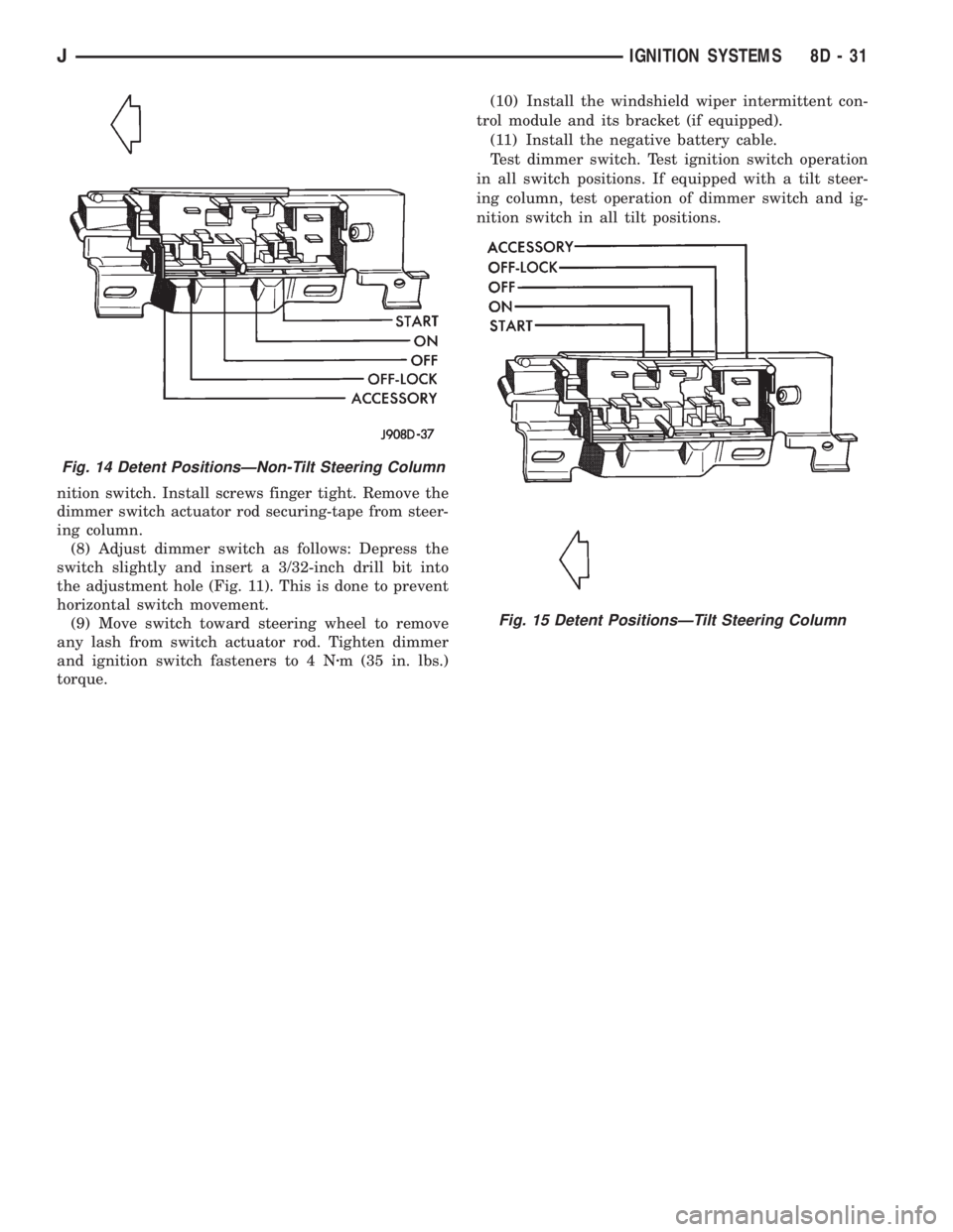
(a) Non-tilt steering column: While holding key
lock switch in ACCESSORY position, gently slide
ignition switchup(towards steering wheel). This
will remove slack from switch. Tighten attaching
screws. Do not allow the ignition switch to move
from the ACCESSORY detent position.
(b) Tilt steering column: While holding the key
lock switch in the ACCESSORY position, gently
slide the ignition switchdown(away from steering
wheel) to remove slack from switch. Tighten at-
taching screws. Do not allow the ignition switch to
move from the ACCESSORY detent position.
Because the ignition switch and the headlamp dim-
mer switch share the same two mounting screws, oneof the screws must be removed from the ignition
switch. This must be doneafterthe ignition switch
has been adjusted andbeforethe dimmer switch
has been installed. Remove one screw.Do notre-
move the stud/nut.
(7) Install the headlamp dimmer switch as follows:
Slip switch into actuator rod and position over the ig-
IGNITION SWITCH CONTINUITY TESTS
Fig. 13 Ignition Switch Terminals/Circuits
8D - 30 IGNITION SYSTEMSJ
Page 355 of 2158
nition switch. Install screws finger tight. Remove the
dimmer switch actuator rod securing-tape from steer-
ing column.
(8) Adjust dimmer switch as follows: Depress the
switch slightly and insert a 3/32-inch drill bit into
the adjustment hole (Fig. 11). This is done to prevent
horizontal switch movement.
(9) Move switch toward steering wheel to remove
any lash from switch actuator rod. Tighten dimmer
and ignition switch fasteners to 4 Nzm (35 in. lbs.)
torque.(10) Install the windshield wiper intermittent con-
trol module and its bracket (if equipped).
(11) Install the negative battery cable.
Test dimmer switch. Test ignition switch operation
in all switch positions. If equipped with a tilt steer-
ing column, test operation of dimmer switch and ig-
nition switch in all tilt positions.
Fig. 14 Detent PositionsÐNon-Tilt Steering Column
Fig. 15 Detent PositionsÐTilt Steering Column
JIGNITION SYSTEMS 8D - 31
Page 369 of 2158
Connect battery negative cable and turn ignition
switch to ON. Lamp should light. If OK, repair open
circuit to brake warning switch. If not OK, replace
bulb.
(5) Turn ignition switch to OFF and remove
jumper wire. Disconnect battery negative cable.
Check for continuity between cavity A (cavity B -
RHD) of brake warning switch connector and a good
ground with ignition switch in START position.
There should be continuity. If not OK, go to next
step.
(6) Turn ignition switch to OFF and remove
jumper wire. Disconnect battery negative cable. Un-
plug ignition switch connector. Check for continuity
between ignition switch connector cavity 3 and a
good ground. There should be no continuity. If OK, go
to next step. If not OK, repair short circuit between
ignition switch and brake warning switch connectors
as required.
(7) Check for continuity between ignition switch
connector cavity 3 and brake warning switch connec-
tor cavity A (cavity B - RHD). There should be conti-
nuity. If OK, go to next step. If not OK, repair open
circuit as required.
(8) Check for continuity between metal steering
column jacket and a good ground. There should be
continuity. If OK, go to next step. If not OK, refer to
Group 19 - Steering to check steering column ground
clip installation.
(9) Turn ignition switch to START position and
hold there. Check for continuity between terminal 3
of ignition switch and a good ground. There should
be continuity. If not OK, replace ignition switch.
(10) Unplug brake warning switch connector.
Check for continuity between parking brake switch
connector and a good ground. There should be no
continuity. If OK, go to next step. If not OK, repair
short circuit as required.
(11) Check for continuity between parking brake
switch connector and cavity B (cavity A - RHD) of
brake warning switch connector. There should be
continuity. If OK, replace parking brake switch. If
not OK, repair open circuit to brake warning switch
as required.
COOLANT TEMPERATURE WARNING LAMP
The diagnosis found here addresses an inoperative
lamp condition. If the problem being diagnosed is re-
lated to lamp accuracy, be certain to confirm that
problem is with lamp and not with cooling system
performance. Actual engine coolant temperature
should be checked with a test gauge or thermometer
before proceeding with lamp diagnosis. Refer to
Group 7 - Cooling System for more information.
(1) Turn ignition switch to START position. Lamp
should light. If OK, go to next step. If not OK, go to
step 3.(2) Turn ignition switch to ON. Disconnect coolant
temperature switch connector (Fig. 1). Jump switch
connector to ground. Lamp should light. If OK, re-
place switch. If not OK, go to next step.
(3) Turn ignition switch to OFF. Disconnect battery
negative cable. Unplug coolant temperature switch
connector. Remove instrument cluster bezel and clus-
ter assembly. Disconnect cluster connector A and
probe cavity A1. Check for continuity to a good
ground. There should be no continuity. If OK, go to
next step. If not OK, repair short circuit to coolant
temperature switch or ignition switch as required.
(4) Connect cluster connector A to cluster. Install a
jumper wire from cavity A1 of cluster connector A to
a good ground. Connect battery negative cable and
turn ignition switch to ON. Lamp should light. If OK,
repair open circuit to coolant temperature switch or
ignition switch as required. If not OK, replace bulb.
FOUR-WHEEL DRIVE INDICATOR LAMPS
(1) Apply parking brake, start engine, vehicle in
4WD Lock or 4WD.
(2) Unplug switch and touch harness side of wire
to ground. Lamp should light. If OK, check switch
operation, replace if bad. If bulb is OK, repair open
to indicator.
GENERATOR WARNING LAMP
(1) Disconnect battery negative cable and unplug
PCM connector. Install a jumper wire between cavity
36 of PCM connector (Fig. 5) and a good ground. Con-
nect battery negative cable and turn ignition switch
to ON. Lamp should light. Unplug jumper wire and
lamp should go off. If OK, refer to Powertrain Diag-
nostic Procedures to check PCM. If not OK, go to
next step.
(2) Turn ignition switch to OFF and disconnect
battery negative cable. Remove instrument cluster
bezel and cluster assembly. Install a jumper wire be-
tween cavity B8 of cluster connector A and a good
ground. Connect battery negative cable and turn ig-
nition switch to ON. Lamp should light. If OK, go to
next step. If not OK, replace bulb.
(3) Turn ignition switch to OFF and disconnect
battery negative cable. Unplug cluster connector A.
Probe cavity B8 of cluster connector A and check for
continuity to a good ground. There should be no con-
tinuity. If OK, go to next step. If not OK, repair short
circuit as required.
(4) Check for continuity between cavity B8 of clus-
ter connector A and cavity 36 of PCM connector.
There should be continuity. If not OK, repair open
circuit as required.
HEADLAMP HIGH BEAM INDICATOR LAMP
(1) Check that headlamp high beams are func-
tional. If OK, go to next step. If not OK, refer to
Group 8L - Lamps for diagnosis of headlamp system.
JINSTRUMENT PANEL AND GAUGESÐXJ 8E - 13
Page 380 of 2158

INSTRUMENT PANEL AND GAUGESÐYJ
CONTENTS
page page
INSTRUMENT PANEL AND GAUGESÐYJ..... 22
DIAGNOSIS............................ 23
GENERAL INFORMATION................. 20SERVICE PROCEDURES.................. 31
SPECIFICATIONS........................ 39
GENERAL INFORMATION
Following are general descriptions of major instru-
ment panel components. Refer to Group 8W - Wiring
Diagrams for complete circuit descriptions and dia-
grams.
INSTRUMENT PANEL
Modular instrument panel construction allows all
gauges and controls to be serviced from the front of
the panel. In addition, most instrument panel wiring
and heater components can be accessed without com-
plete instrument panel removal.
Removal of the left instrument cluster bezel allows
access to the main cluster assembly and most
switches. Removal of the center cluster bezel allows
access to the gauge package cluster assembly, the
heater controls, and the radio. Removal of the cluster
assemblies allows access to the individual gauges, il-
lumination and indicator lamp bulbs, printed cir-
cuits, and most wiring.
INSTRUMENT CLUSTERS
The instrument cluster used on YJ (Wrangler) mod-
els consists of two separate assemblies. The main
cluster assembly is located on the left side of the in-
strument panel, centered over the steering column
opening. The gauge package cluster assembly is lo-
cated near the center of the instrument panel. Each
cluster assembly is served by a separate printed cir-
cuit and wiring connector. Some variations of each
cluster exist due to optional equipment and regula-
tory requirements.
The main cluster assembly includes a speedometer/
odometer/trip odometer and a tachometer. It also in-
cludes provisions for the following indicator lamps:
²anti-lock brake system lamp
²brake warning lamp
²headlamp high beam indicator lamp
²malfunction indicator (Check Engine) lamp
²seat belt reminder lamp²turn signal indicator lamps
²upshift indicator lamp.
The gauge package cluster assembly includes a
four-wheel drive indicator lamp and the following
gauges:
²coolant temperature gauge
²fuel gauge
²oil pressure gauge
²voltmeter.
GAUGES
With the ignition switch in the ON or START posi-
tion, voltage is supplied to all gauges through the
two cluster printed circuits. With the ignition switch
in the OFF position, voltage is not supplied to the
gauges. A gauge pointer may remain within the
gauge scale after the ignition switch is OFF. How-
ever, the gauges do not accurately indicate any vehi-
cle condition unless the ignition switch is ON.
All gauges except the odometer are air core mag-
netic units. Two fixed electromagnetic coils are lo-
cated within the gauge. These coils are wrapped at
right angles to each other around a movable perma-
nent magnet. The movable magnet is suspended
within the coils on one end of a shaft. The gauge nee-
dle is attached to the other end of the shaft.
One of the coils has a fixed current flowing through
it to maintain a constant magnetic field strength.
Current flow through the second coil changes, which
causes changes in its magnetic field strength. The
current flowing through the second coil can be
changed by:
²a variable resistor-type sending unit (fuel level,
coolant temperature, or oil pressure)
²changes in electrical system voltage (voltmeter)
²electronic control circuitry (speedometer/odometer,
tachometer).
8E - 24 INSTRUMENT PANEL AND GAUGESÐYJJ
Page 381 of 2158

The gauge needle moves as the movable permanent
magnet aligns itself to the changing magnetic fields
created around it by the electromagnets.
COOLANT TEMPERATURE GAUGE
The coolant temperature gauge gives an indication
of engine coolant temperature. The coolant tempera-
ture sending unit is a thermistor that changes elec-
trical resistance with changes in engine coolant
temperature. High sending unit resistance causes
low coolant temperature readings. Low resistance
causes high coolant temperature readings. Sending
unit resistance values are shown in a chart in Spec-
ifications.
FUEL GAUGE
The fuel gauge gives an indication of the level of
fuel in the fuel tank. The fuel gauge sending unit has
a float attached to a swing-arm in the fuel tank. The
float moves up or down within the fuel tank as fuel
level changes. As the float moves, an electrical con-
tact on the swing-arm wipes across a resistor coil,
which changes sending unit resistance. High sending
unit resistance causes high fuel level readings. Low
resistance causes low fuel level readings. Sending
unit resistance values are shown in a chart in Spec-
ifications.
OIL PRESSURE GAUGE
The oil pressure gauge gives an indication of en-
gine oil pressure. The combination oil pressure send-
ing unit contains a flexible diaphragm. The
diaphragm moves in response to changes in engine
oil pressure. As the diaphragm moves, sending unit
resistance increases or decreases. High resistance on
the gauge side of the sending unit causes high oil
pressure readings. Low resistance causes low oil
pressure readings. Sending unit resistance values are
shown in a chart in Specifications.
SPEEDOMETER/ODOMETER
The speedometer/odometer give an indication of ve-
hicle speed and travel distance. The speedometer re-
ceives a vehicle speed pulse signal from the Vehicle
Speed Sensor (VSS). An electronic integrated circuit
contained within the speedometer reads and analyzes
the pulse signal. It then adjusts the ground path re-
sistance of one electromagnet in the gauge to control
needle movement. It also sends signals to an electric
stepper motor to control movement of the odometer
number rolls. Frequency values for the pulse signal
are shown in a chart in Specifications.
The VSS is mounted to an adapter near the trans-
fer case output shaft. The sensor is driven through
the adapter by a speedometer pinion gear. The
adapter and pinion vary with transmission, axle ratio
and tire size. Refer to Group 21 - Transmission and
Transfer Case for more information.
TACHOMETER
The tachometer gives an indication of engine speed
in Revolutions-Per-Minute (RPM). With the engine
running, the tachometer receives an engine speed
pulse signal from the Powertrain Control Module
(PCM). An electronic integrated circuit contained
within the tachometer reads and analyzes the pulse
signal. It then adjusts the ground path resistance of
one electromagnet in the gauge to control needle
movement. Frequency values for the pulse signal are
shown in a chart in Specifications.
TRIP ODOMETER
The trip odometer is driven by the same electronic
integrated circuit as the speedometer/odometer. How-
ever, by depressing the trip odometer reset knob on
the face of the speedometer, the trip odometer can be
reset to zero. The trip odometer is serviced only as a
part of the speedometer/odometer gauge assembly.
VOLTMETER
The voltmeter is connected in parallel with the bat-
tery. With the ignition switch ON, the voltmeter in-
dicates battery or generator output voltage,
whichever is greater.
INDICATOR LAMPS
All indicator lamps, except the four-wheel drive in-
dicator, are located in the main cluster tell-tale area
above the steering column opening. Each of the
lamps is served by the main cluster printed circuit
and cluster connector. The four-wheel drive indicator
lamp is located in the gauge package cluster and is
served by the gauge package printed circuit and clus-
ter connector.
Up to eleven indicator lamps can be found in the
tell-tale area of the main cluster. These lamps are ar-
ranged in two rows, with six lamps in the upper row
and five lamps in the lower row.
ANTI-LOCK BRAKE SYSTEM LAMP
The Anti-Lock Brake System (ABS) lamp is
switched to ground by the ABS module. The module
lights the lamp when the ignition switch is turned to
the START position as a bulb test. The lamp will
stay on for 3 to 5 seconds after vehicle start-up to in-
dicate a system self-test is in process. If the lamp re-
mains on after start-up, or comes on and stays on
while driving, it may indicate that the ABS module
has detected a system malfunction or that the system
has become inoperative. Refer to Group 5 - Brakes
for more information.
BRAKE WARNING LAMP
The brake warning lamp warns the driver that the
parking brake is applied or that the pressures in the
two halves of the split brake hydraulic system are
unequal. With the ignition switch turned ON, battery
JINSTRUMENT PANEL AND GAUGESÐYJ 8E - 25
Page 390 of 2158
TURN SIGNAL INDICATOR LAMPS
(1) Disconnect battery negative cable. Remove left
instrument cluster bezel and main cluster assembly.
Probe cavity 20 of cluster connector. Check for conti-
nuity to a good ground. There should be continuity. If
OK, go to next step. If not OK, repair open circuit to
ground.
(2) Connect battery negative cable. Install a
jumper wire from cavity 18 (left indicator) or cavity 7
(right indicator) of cluster connector to a 12-volt bat-
tery feed. Lamp should light. If OK, continue to next
step. If not OK, replace bulb.
(3) Disconnect battery negative cable. Check for
continuity between cavity 18 (left indicator) or cavity
7 (right indicator) of cluster connector and cavity H
(left front turn signal) or cavity J (right front turn
signal) of steering column wiring connector. There
should be continuity. If OK, refer to Group 8J - Turn
Signal and Hazard Warning Systems for further di-
agnosis. If not OK, repair open circuit as required.
UPSHIFT INDICATOR LAMP
(1) Disconnect battery negative cable. Unplug PCM
connector. Connect battery negative cable. Turn igni-
tion switch to ON. Install a jumper wire from cavity
54 of PCM connector (Fig. 5) to a good ground. Lamp
should light. Remove jumper from ground. Lamp
should go off. If OK, refer to Powertrain Diagnostic
Procedures manual to diagnose PCM. If not OK, turn
ignition switch to OFF and go to next step.
(2) Disconnect battery negative cable. Remove left
instrument cluster bezel and main cluster assembly.
Install a jumper wire from cavity 5 of cluster connec-
tor to a good ground. Connect battery negative cable.
Turn ignition switch to ON. Lamp should light. If
OK, go to next step. If not OK, replace bulb.
(3) Turn ignition switch to OFF. Disconnect battery
negative cable. Unplug cluster connector. Check for
continuity between cavity 5 of cluster connector and
a good ground. There should be no continuity. If OK,
go to next step. If not OK, repair short circuit as re-
quired.(4) Check for continuity between cavity 5 of cluster
connector and cavity 54 of PCM connector. There
should be continuity. If not OK, repair open circuit as
required.
CLUSTER ILLUMINATION LAMPS
(1) Check fuse 10 in fuseblock module. If OK, go to
next step. If not OK, replace fuse.
(2) Turn park lamps on at headlamp switch. Rotate
panel dimmer switch thumb-wheel to HI position,
just before interior lamps detent. Check for battery
voltage at fuse 10 in fuseblock module. Rotate panel
dimmer thumb-wheel towards LO position while ob-
serving test voltmeter. Reading should go from bat-
tery voltage to zero volts. If OK, go to next step. If
not OK, repair open circuit to headlamp switch or re-
fer to Group 8L - Lamps to diagnose headlamp
switch.
(3) Disconnect battery negative cable. Remove left
or center instrument cluster bezel and main or gauge
package cluster assembly. Unplug cluster connector.
Connect battery negative cable. Turn park lamps on
at headlamp switch. Rotate panel dimmer thumb-
wheel to HI position, just before interior lamps de-
tent. Check for battery voltage at cavity 21 of main
cluster connector, or cavity 7 of gauge package clus-
ter connector. If OK, go to next step. If not OK, re-
pair open circuit to fuse as required.
(4) Turn park lamps off. Disconnect battery nega-
tive cable. Remove fuse 10 from fuseblock module.
Probe cavity 21 of main cluster connector, or cavity 7
of gauge package cluster connector. Check for conti-
nuity to a good ground. There should be no continu-
ity. If OK, go to next step. If not OK, repair short
circuit as required.
(5) Probe cavity 20 of main cluster connector, or
cavities 1 and 13 of gauge package cluster connector.
Check for continuity to ground. There should be con-
tinuity. If not OK, repair open circuit as required.
8E - 34 INSTRUMENT PANEL AND GAUGESÐYJJ
Page 391 of 2158
SERVICE PROCEDURES
CLUSTER ASSEMBLY REMOVE/INSTALL
MAIN CLUSTER
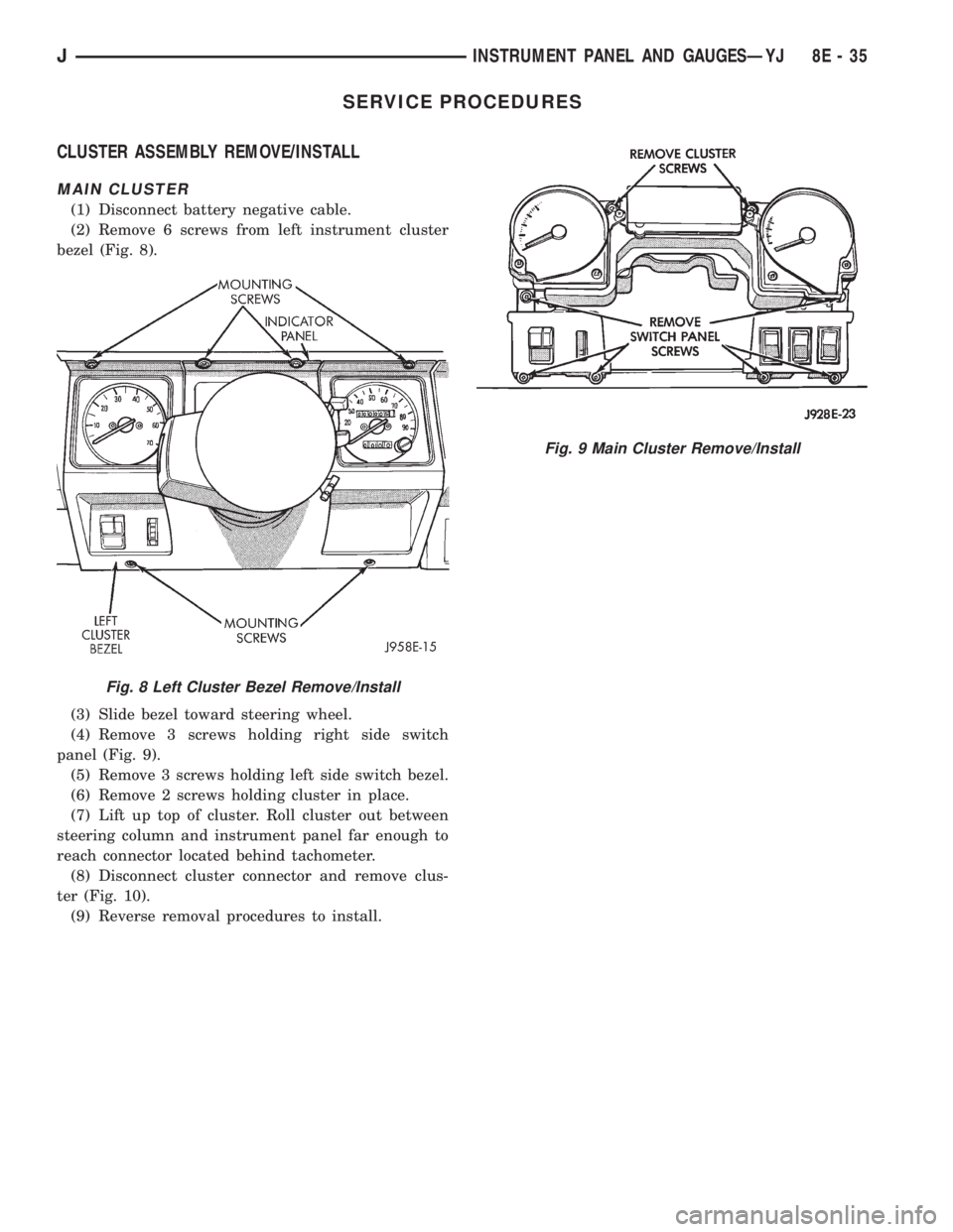
(1) Disconnect battery negative cable.
(2) Remove 6 screws from left instrument cluster
bezel (Fig. 8).
(3) Slide bezel toward steering wheel.
(4) Remove 3 screws holding right side switch
panel (Fig. 9).
(5) Remove 3 screws holding left side switch bezel.
(6) Remove 2 screws holding cluster in place.
(7) Lift up top of cluster. Roll cluster out between
steering column and instrument panel far enough to
reach connector located behind tachometer.
(8) Disconnect cluster connector and remove clus-
ter (Fig. 10).
(9) Reverse removal procedures to install.
Fig. 8 Left Cluster Bezel Remove/Install
Fig. 9 Main Cluster Remove/Install
JINSTRUMENT PANEL AND GAUGESÐYJ 8E - 35
Page 398 of 2158
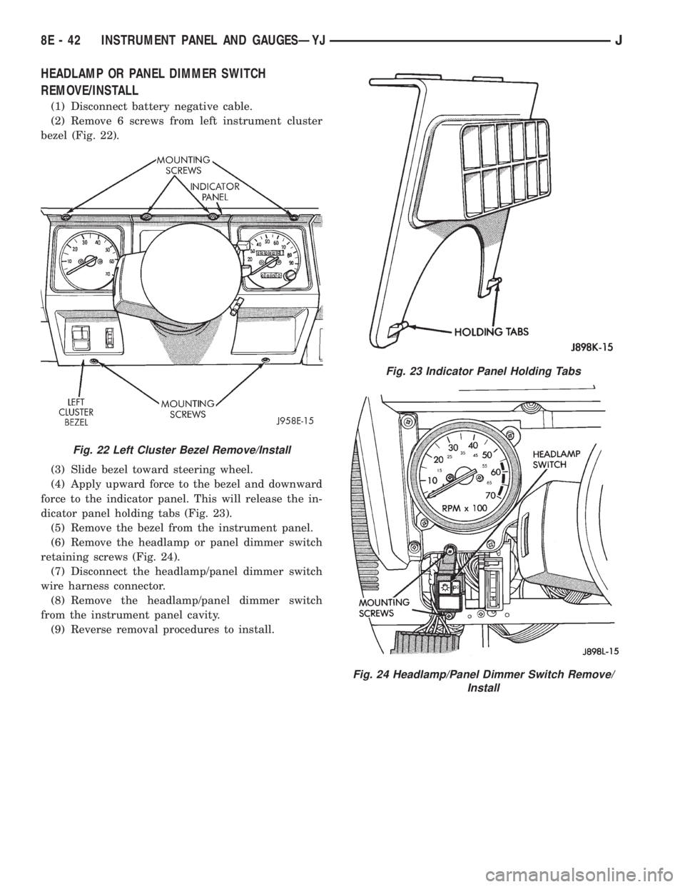
HEADLAMP OR PANEL DIMMER SWITCH
REMOVE/INSTALL
(1) Disconnect battery negative cable.
(2) Remove 6 screws from left instrument cluster
bezel (Fig. 22).
(3) Slide bezel toward steering wheel.
(4) Apply upward force to the bezel and downward
force to the indicator panel. This will release the in-
dicator panel holding tabs (Fig. 23).
(5) Remove the bezel from the instrument panel.
(6) Remove the headlamp or panel dimmer switch
retaining screws (Fig. 24).
(7) Disconnect the headlamp/panel dimmer switch
wire harness connector.
(8) Remove the headlamp/panel dimmer switch
from the instrument panel cavity.
(9) Reverse removal procedures to install.
Fig. 22 Left Cluster Bezel Remove/Install
Fig. 23 Indicator Panel Holding Tabs
Fig. 24 Headlamp/Panel Dimmer Switch Remove/
Install
8E - 42 INSTRUMENT PANEL AND GAUGESÐYJJ