1995 JEEP YJ clock
[x] Cancel search: clockPage 1549 of 2158
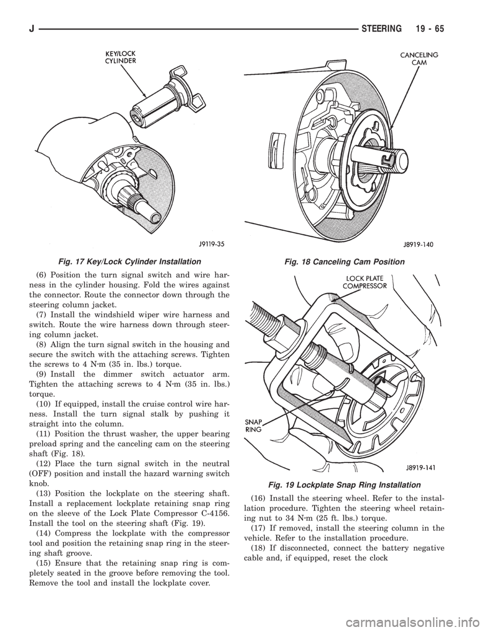
(6) Position the turn signal switch and wire har-
ness in the cylinder housing. Fold the wires against
the connector. Route the connector down through the
steering column jacket.
(7) Install the windshield wiper wire harness and
switch. Route the wire harness down through steer-
ing column jacket.
(8) Align the turn signal switch in the housing and
secure the switch with the attaching screws. Tighten
the screws to 4 Nzm (35 in. lbs.) torque.
(9) Install the dimmer switch actuator arm.
Tighten the attaching screws to 4 Nzm (35 in. lbs.)
torque.
(10) If equipped, install the cruise control wire har-
ness. Install the turn signal stalk by pushing it
straight into the column.
(11) Position the thrust washer, the upper bearing
preload spring and the canceling cam on the steering
shaft (Fig. 18).
(12) Place the turn signal switch in the neutral
(OFF) position and install the hazard warning switch
knob.
(13) Position the lockplate on the steering shaft.
Install a replacement lockplate retaining snap ring
on the sleeve of the Lock Plate Compressor C-4156.
Install the tool on the steering shaft (Fig. 19).
(14) Compress the lockplate with the compressor
tool and position the retaining snap ring in the steer-
ing shaft groove.
(15) Ensure that the retaining snap ring is com-
pletely seated in the groove before removing the tool.
Remove the tool and install the lockplate cover.(16) Install the steering wheel. Refer to the instal-
lation procedure. Tighten the steering wheel retain-
ing nut to 34 Nzm (25 ft. lbs.) torque.
(17) If removed, install the steering column in the
vehicle. Refer to the installation procedure.
(18) If disconnected, connect the battery negative
cable and, if equipped, reset the clock
Fig. 17 Key/Lock Cylinder InstallationFig. 18 Canceling Cam Position
Fig. 19 Lockplate Snap Ring Installation
JSTEERING 19 - 65
Page 1550 of 2158
TILT STEERING COLUMN
DISASSEMBLY
(1) Remove the steering column from the vehicle, if
necessary. Refer to the removal procedure.
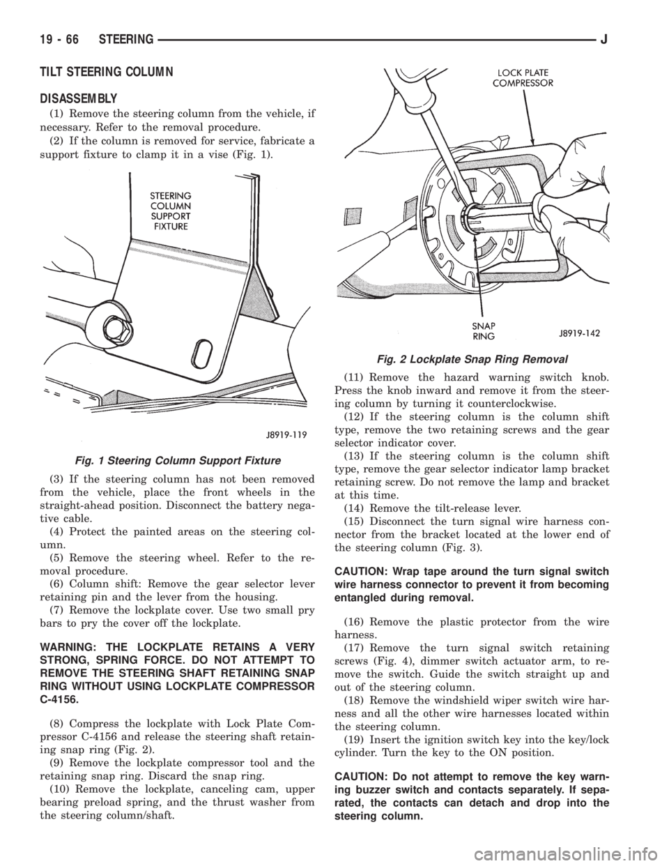
(2) If the column is removed for service, fabricate a
support fixture to clamp it in a vise (Fig. 1).
(3) If the steering column has not been removed
from the vehicle, place the front wheels in the
straight-ahead position. Disconnect the battery nega-
tive cable.
(4) Protect the painted areas on the steering col-
umn.
(5) Remove the steering wheel. Refer to the re-
moval procedure.
(6) Column shift: Remove the gear selector lever
retaining pin and the lever from the housing.
(7) Remove the lockplate cover. Use two small pry
bars to pry the cover off the lockplate.
WARNING: THE LOCKPLATE RETAINS A VERY
STRONG, SPRING FORCE. DO NOT ATTEMPT TO
REMOVE THE STEERING SHAFT RETAINING SNAP
RING WITHOUT USING LOCKPLATE COMPRESSOR
C-4156.
(8) Compress the lockplate with Lock Plate Com-
pressor C-4156 and release the steering shaft retain-
ing snap ring (Fig. 2).
(9) Remove the lockplate compressor tool and the
retaining snap ring. Discard the snap ring.
(10) Remove the lockplate, canceling cam, upper
bearing preload spring, and the thrust washer from
the steering column/shaft.(11) Remove the hazard warning switch knob.
Press the knob inward and remove it from the steer-
ing column by turning it counterclockwise.
(12) If the steering column is the column shift
type, remove the two retaining screws and the gear
selector indicator cover.
(13) If the steering column is the column shift
type, remove the gear selector indicator lamp bracket
retaining screw. Do not remove the lamp and bracket
at this time.
(14) Remove the tilt-release lever.
(15) Disconnect the turn signal wire harness con-
nector from the bracket located at the lower end of
the steering column (Fig. 3).
CAUTION: Wrap tape around the turn signal switch
wire harness connector to prevent it from becoming
entangled during removal.
(16) Remove the plastic protector from the wire
harness.
(17) Remove the turn signal switch retaining
screws (Fig. 4), dimmer switch actuator arm, to re-
move the switch. Guide the switch straight up and
out of the steering column.
(18) Remove the windshield wiper switch wire har-
ness and all the other wire harnesses located within
the steering column.
(19) Insert the ignition switch key into the key/lock
cylinder. Turn the key to the ON position.
CAUTION: Do not attempt to remove the key warn-
ing buzzer switch and contacts separately. If sepa-
rated, the contacts can detach and drop into the
steering column.
Fig. 1 Steering Column Support Fixture
Fig. 2 Lockplate Snap Ring Removal
19 - 66 STEERINGJ
Page 1551 of 2158
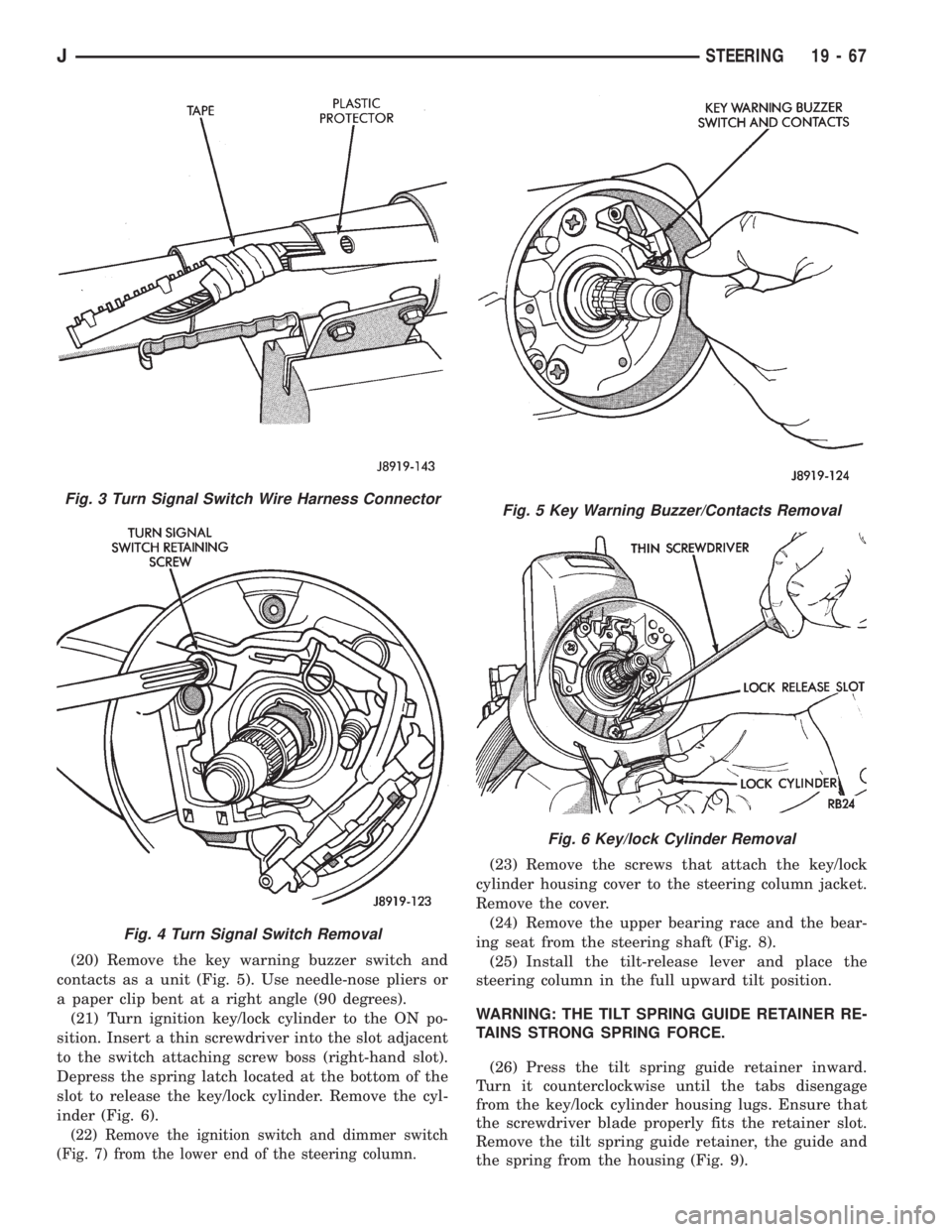
(20) Remove the key warning buzzer switch and
contacts as a unit (Fig. 5). Use needle-nose pliers or
a paper clip bent at a right angle (90 degrees).
(21) Turn ignition key/lock cylinder to the ON po-
sition. Insert a thin screwdriver into the slot adjacent
to the switch attaching screw boss (right-hand slot).
Depress the spring latch located at the bottom of the
slot to release the key/lock cylinder. Remove the cyl-
inder (Fig. 6).
(22) Remove the ignition switch and dimmer switch
(Fig. 7) from the lower end of the steering column.
(23) Remove the screws that attach the key/lock
cylinder housing cover to the steering column jacket.
Remove the cover.
(24) Remove the upper bearing race and the bear-
ing seat from the steering shaft (Fig. 8).
(25) Install the tilt-release lever and place the
steering column in the full upward tilt position.
WARNING: THE TILT SPRING GUIDE RETAINER RE-
TAINS STRONG SPRING FORCE.
(26) Press the tilt spring guide retainer inward.
Turn it counterclockwise until the tabs disengage
from the key/lock cylinder housing lugs. Ensure that
the screwdriver blade properly fits the retainer slot.
Remove the tilt spring guide retainer, the guide and
the spring from the housing (Fig. 9).
Fig. 3 Turn Signal Switch Wire Harness Connector
Fig. 4 Turn Signal Switch Removal
Fig. 5 Key Warning Buzzer/Contacts Removal
Fig. 6 Key/lock Cylinder Removal
JSTEERING 19 - 67
Page 1552 of 2158
(27) Position the steering column in the center,
non-tilt position.
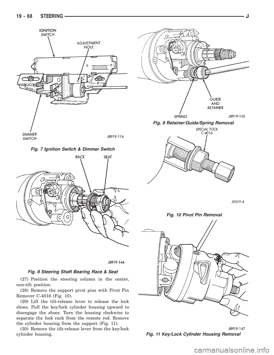
(28) Remove the support pivot pins with Pivot Pin
Remover C-4016 (Fig. 10).
(29) Lift the tilt-release lever to release the lock
shoes. Pull the key/lock cylinder housing upward to
disengage the shoes. Turn the housing clockwise to
separate the lock rack from the remote rod. Remove
the cylinder housing from the support (Fig. 11).
(30) Remove the tilt-release lever from the key/lock
cylinder housing.
Fig. 10 Pivot Pin Removal
Fig. 11 Key/Lock Cylinder Housing Removal
Fig. 7 Ignition Switch & Dimmer Switch
Fig. 8 Steering Shaft Bearing Race & Seat
Fig. 9 Retainer/Guide/Spring Removal
19 - 68 STEERINGJ
Page 1553 of 2158
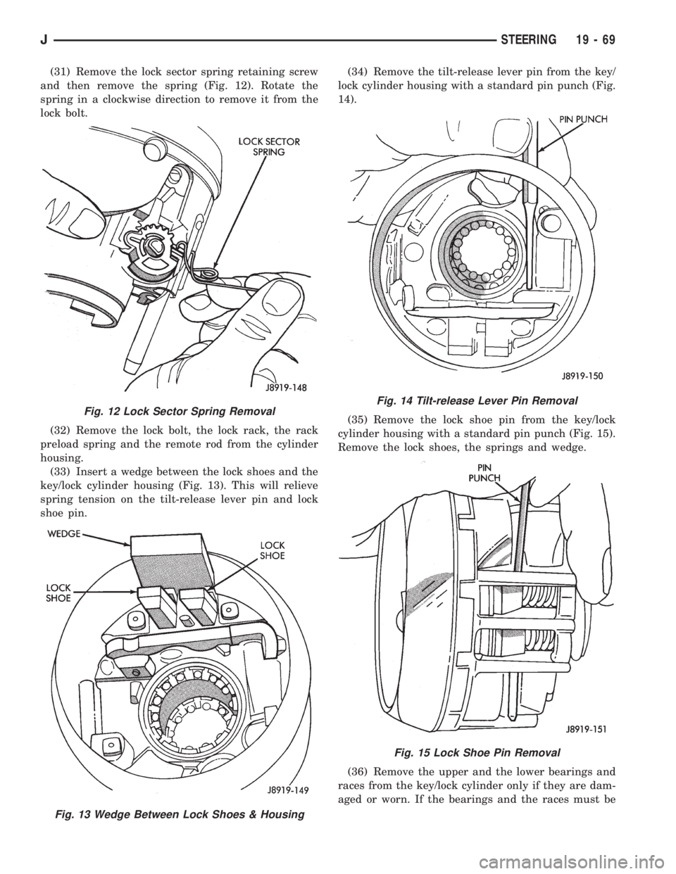
(31) Remove the lock sector spring retaining screw
and then remove the spring (Fig. 12). Rotate the
spring in a clockwise direction to remove it from the
lock bolt.
(32) Remove the lock bolt, the lock rack, the rack
preload spring and the remote rod from the cylinder
housing.
(33) Insert a wedge between the lock shoes and the
key/lock cylinder housing (Fig. 13). This will relieve
spring tension on the tilt-release lever pin and lock
shoe pin.(34) Remove the tilt-release lever pin from the key/
lock cylinder housing with a standard pin punch (Fig.
14).
(35) Remove the lock shoe pin from the key/lock
cylinder housing with a standard pin punch (Fig. 15).
Remove the lock shoes, the springs and wedge.
(36) Remove the upper and the lower bearings and
races from the key/lock cylinder only if they are dam-
aged or worn. If the bearings and the races must be
Fig. 12 Lock Sector Spring Removal
Fig. 13 Wedge Between Lock Shoes & Housing
Fig. 14 Tilt-release Lever Pin Removal
Fig. 15 Lock Shoe Pin Removal
JSTEERING 19 - 69
Page 1554 of 2158
replaced, remove them with a hammer and punch.
Discard the bearings and races after removal. They
are not reusable.
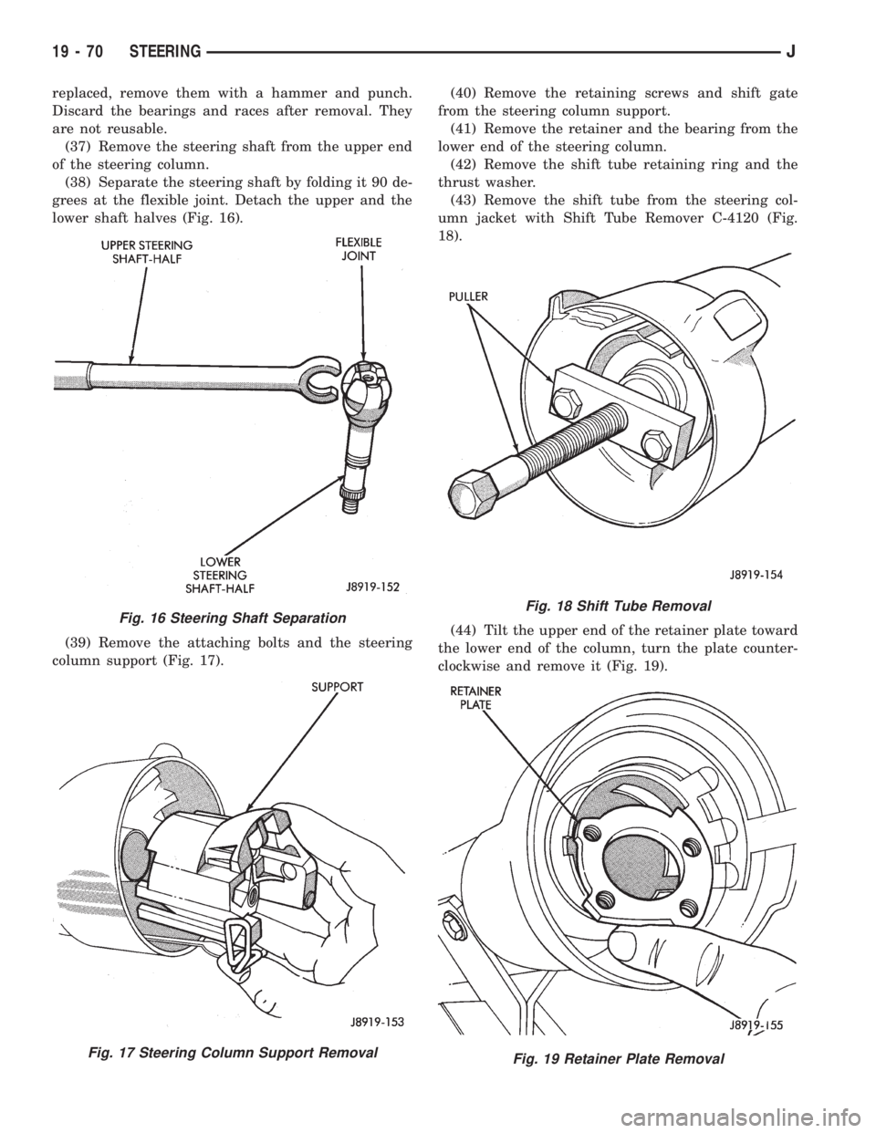
(37) Remove the steering shaft from the upper end
of the steering column.
(38) Separate the steering shaft by folding it 90 de-
grees at the flexible joint. Detach the upper and the
lower shaft halves (Fig. 16).
(39) Remove the attaching bolts and the steering
column support (Fig. 17).(40) Remove the retaining screws and shift gate
from the steering column support.
(41) Remove the retainer and the bearing from the
lower end of the steering column.
(42) Remove the shift tube retaining ring and the
thrust washer.
(43) Remove the shift tube from the steering col-
umn jacket with Shift Tube Remover C-4120 (Fig.
18).
(44) Tilt the upper end of the retainer plate toward
the lower end of the column, turn the plate counter-
clockwise and remove it (Fig. 19).
Fig. 16 Steering Shaft Separation
Fig. 17 Steering Column Support Removal
Fig. 18 Shift Tube Removal
Fig. 19 Retainer Plate Removal
19 - 70 STEERINGJ
Page 1556 of 2158
(9) Install the shift tube thrust washer and the re-
tainer plate snap ring.
(10) Install the lower bearing in the steering col-
umn.
(11) Position the shift gate in the steering column
support. Install the attaching screws.
(12) Position the support in the steering column.
(13) Install all support attaching screws finger-
tight. Next, tighten the screws alternately and evenly
to7Nzm (60 in. lbs.) torque.
(14) Install the remote rod in the support. Route
the rod through the upper end of the shroud and in-
sert it into the rod slot located in the support.
(15) Install the dimmer switch and ignition switch.
(16) Install the steering shaft in the steering col-
umn.
(17) Install replacement races and bearings in the
key/lock cylinder, if removed.Ensure that the bear-
ings are lubricated with chassis lubricant be-
fore installation.
(18) Install the lock shoes, the lock shoe springs
and the lock shoe pin the key/lock cylinder housing.
Use a 4.5-mm (0.18-in) diameter rod to align the
shoes and the pin during installation.
(19) Install the tilt-release lever, the lever spring
and the lever pin in the key/lock cylinder housing.
Insert a wedge between the housing and the lever to
relieve the spring tension. This will allow easier re-
lease lever pin installation.
(20) Install the lock bolt in the key/lock cylinder
housing and engage it in the lock sector cam surface.
(21) Install the lock rack, the rack preload spring
and a replacement shim in the key/lock cylinder
housing. Align and mate the square block tooth on
the lock rack and the lock sector.
(22) Install the lock spring and the spring retain-
ing screw. Tighten the screw to 4 Nzm (35 in. lbs.)
torque.
(23) Align and install the assembled key/lock cylin-
der housing on the support. Retain the lock shoes in
the disengaged position for easier housing installa-
tion.
(24) Align the pivot pin holes in the housing with
those in the support. Insert the pivot pins.Press the
housing firmly downward when inserting the
pivot pins. This prevents damaging the holes in
the support.When the pivot pins are within both
the housing and the support holes, seat them fully
with a punch and a hammer.
(25) Insert tilt-release lever in key/lock cylinder
housing and place housing in the full-upward tilt po-
sition.
(26) Lubricate the tilt spring guide and the tilt
spring liberally with chassis lubricant and position
the spring on the guide.
(27) Insert the tilt spring guide and the spring into
the key/lock cylinder housing. Install the guide re-tainer over the spring. Engage the retainer lock tabs
with the housing lugs by pressing the retainer down-
ward and turning clockwise with a screwdriver.
(28) Place the cover on the key/lock cylinder hous-
ing. Align and install the cover retaining screws.
Tighten the screws to 7 Nzm (60 in. lbs.) torque.
(29) Install the gear selector indicator lamp mount-
ing bracket screw.
(30) Install the gear selector indicator cover and
retaining screws.
(31) Route the dimmer switch wire harness and
gear selector indicator down through the steering col-
umn.
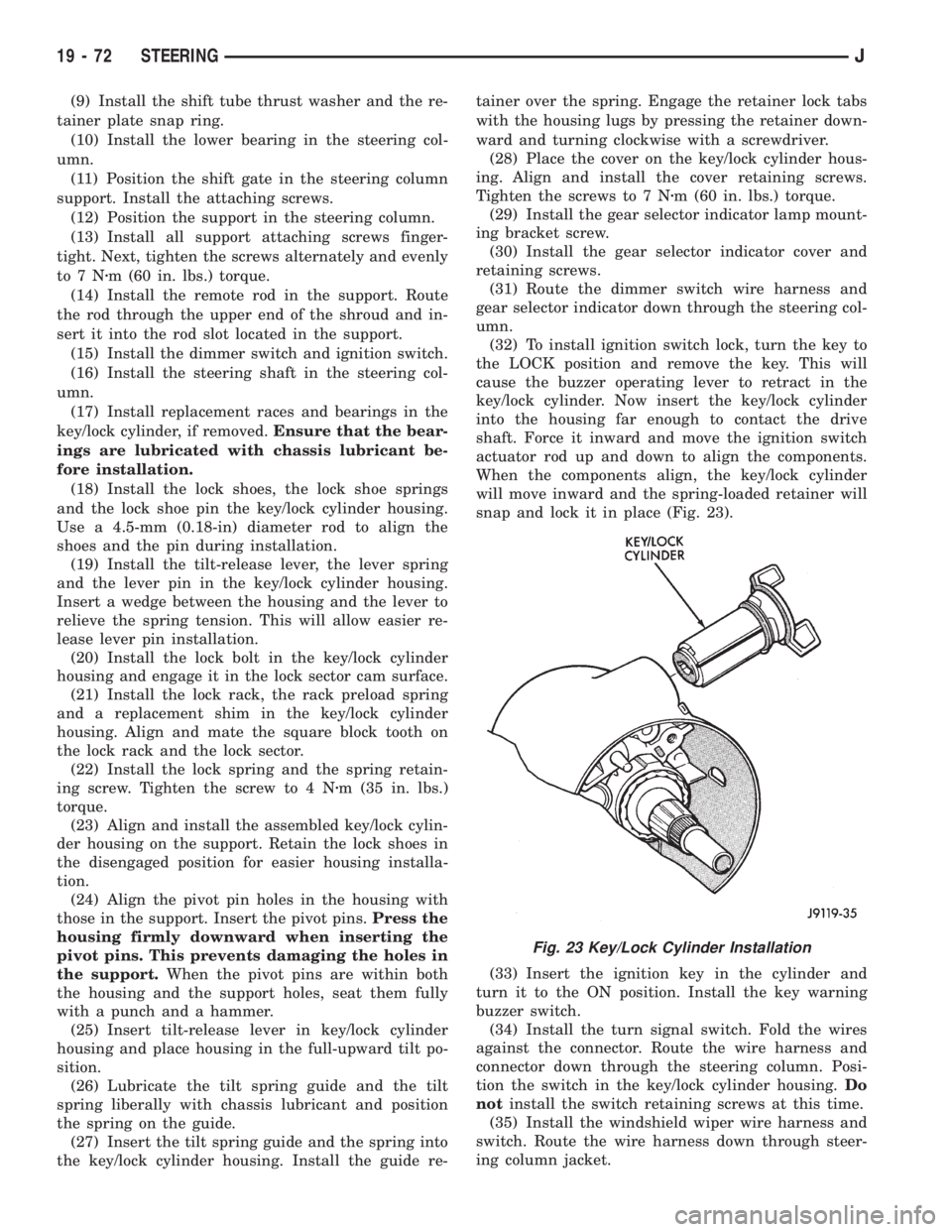
(32) To install ignition switch lock, turn the key to
the LOCK position and remove the key. This will
cause the buzzer operating lever to retract in the
key/lock cylinder. Now insert the key/lock cylinder
into the housing far enough to contact the drive
shaft. Force it inward and move the ignition switch
actuator rod up and down to align the components.
When the components align, the key/lock cylinder
will move inward and the spring-loaded retainer will
snap and lock it in place (Fig. 23).
(33) Insert the ignition key in the cylinder and
turn it to the ON position. Install the key warning
buzzer switch.
(34) Install the turn signal switch. Fold the wires
against the connector. Route the wire harness and
connector down through the steering column. Posi-
tion the switch in the key/lock cylinder housing.Do
notinstall the switch retaining screws at this time.
(35) Install the windshield wiper wire harness and
switch. Route the wire harness down through steer-
ing column jacket.
Fig. 23 Key/Lock Cylinder Installation
19 - 72 STEERINGJ
Page 1560 of 2158
(4) Tighten fittings at pump and gear to 28 Nzm
(21 ft. lbs.) torque.
(5) After installation, add power steering fluid, in-
spect and test for fluid leaks.
PUMP REPLACEMENT
REMOVAL
(1) Remove and cap pressure and return lines from
pump. Refer to Pressure and Return Line Replace-
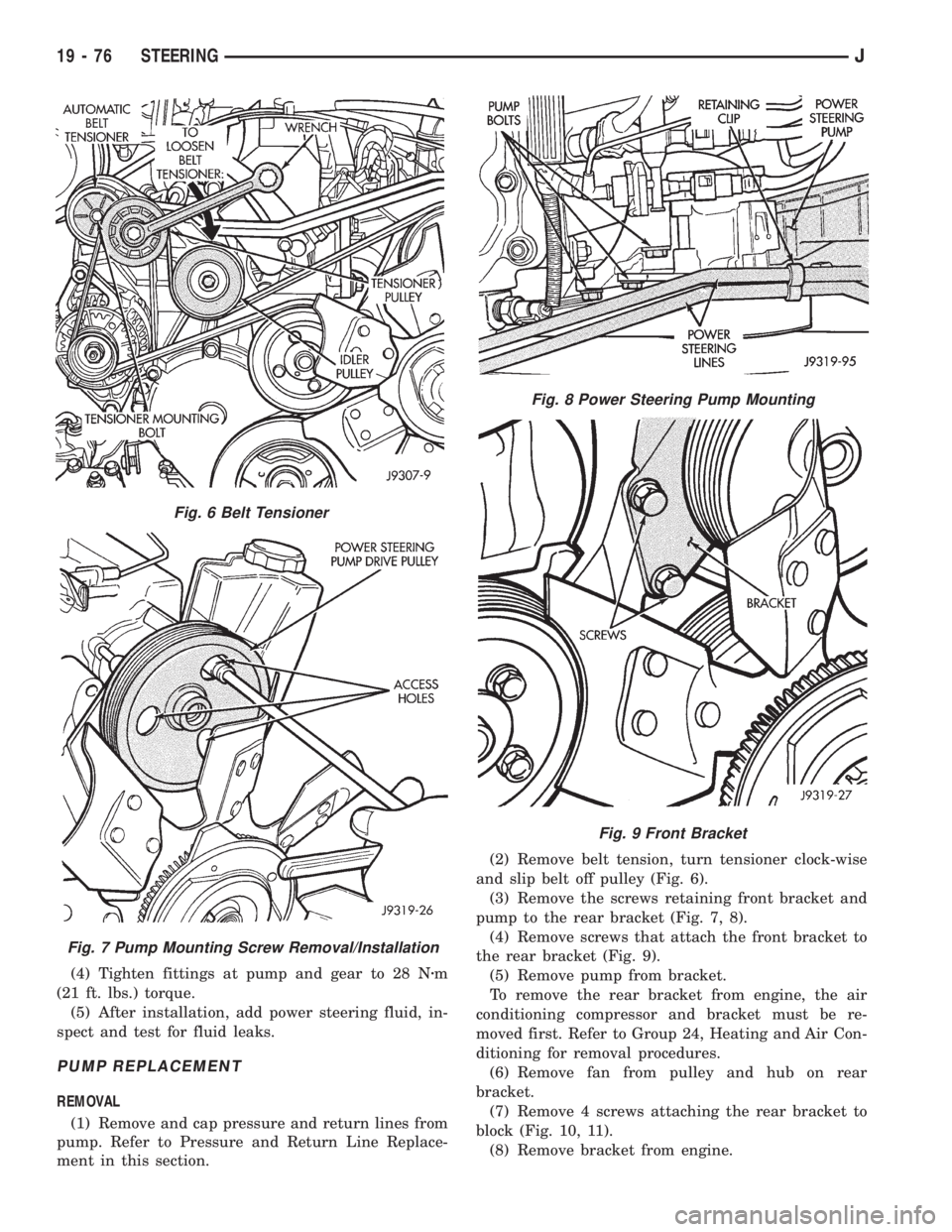
ment in this section.(2) Remove belt tension, turn tensioner clock-wise
and slip belt off pulley (Fig. 6).
(3) Remove the screws retaining front bracket and
pump to the rear bracket (Fig. 7, 8).
(4) Remove screws that attach the front bracket to
the rear bracket (Fig. 9).
(5) Remove pump from bracket.
To remove the rear bracket from engine, the air
conditioning compressor and bracket must be re-
moved first. Refer to Group 24, Heating and Air Con-
ditioning for removal procedures.
(6) Remove fan from pulley and hub on rear
bracket.
(7) Remove 4 screws attaching the rear bracket to
block (Fig. 10, 11).
(8) Remove bracket from engine.
Fig. 6 Belt Tensioner
Fig. 7 Pump Mounting Screw Removal/Installation
Fig. 8 Power Steering Pump Mounting
Fig. 9 Front Bracket
19 - 76 STEERINGJ