Page 1807 of 2158
Race should turn freely counterclockwise, but lock
when turned clockwise. Replace one-way clutch if
necessary.
(7) Remove clutch inner race from planetary gear
(Fig. 7).
(8) Remove clutch snap ring and remove No. 2 one-
way clutch from planetary (Fig. 8).
(9) Remove front and rear thrust washers from
planetary gear (Fig. 9).
(10) Remove thrust bearing and washers from ring
gear (Fig. 10).
(11) Remove ring gear snap ring and remove ring
gear hub (Fig. 11).
Fig. 3 Removing/Installing Shaft Seal Ring
Fig. 4 Removing/Installing First-Reverse Brake Pack
Fig. 5 Removing/Installing Rear Planetary
Fig. 6 Checking No. 2 One-Way Clutch Operation
Fig. 7 Removing/Installing Clutch Inner Race
JAW-4 TRANSMISSION OVERHAUL 21 - 245
Page 1808 of 2158
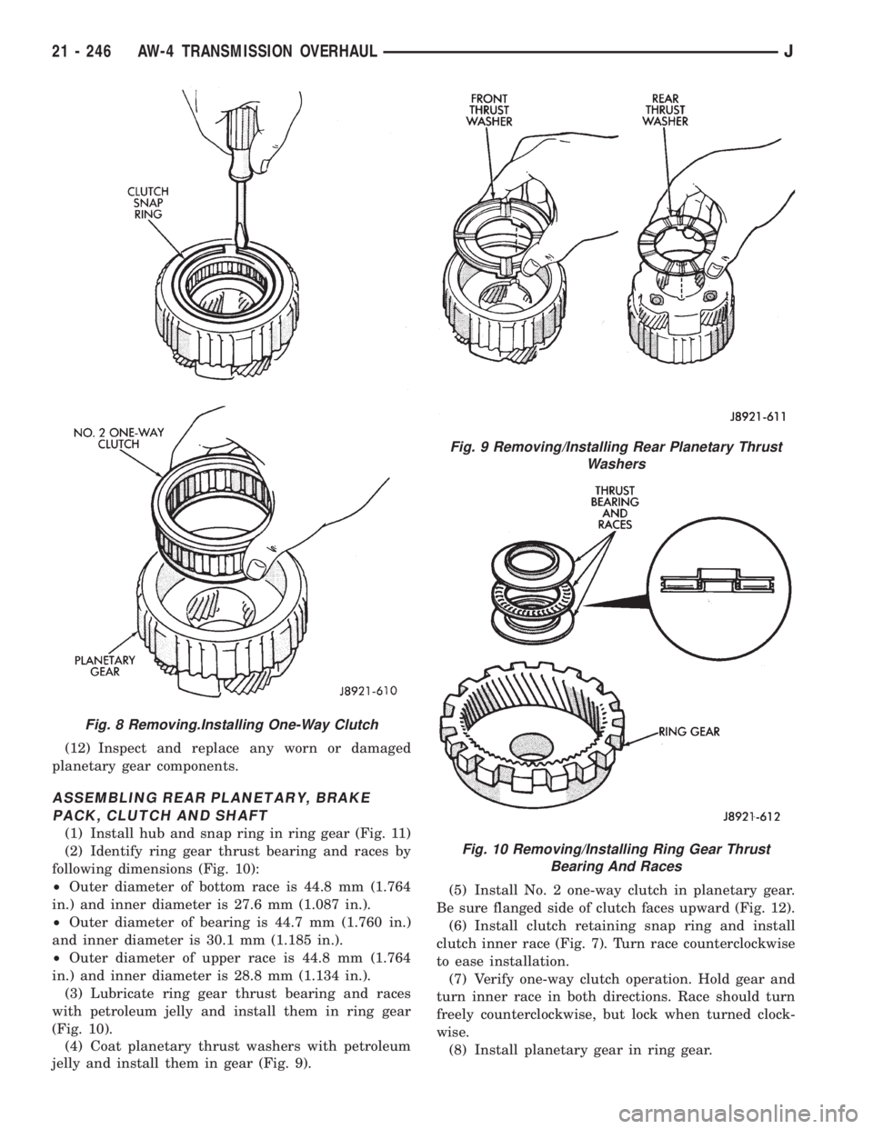
(12) Inspect and replace any worn or damaged
planetary gear components.
ASSEMBLING REAR PLANETARY, BRAKE
PACK, CLUTCH AND SHAFT
(1) Install hub and snap ring in ring gear (Fig. 11)
(2) Identify ring gear thrust bearing and races by
following dimensions (Fig. 10):
²Outer diameter of bottom race is 44.8 mm (1.764
in.) and inner diameter is 27.6 mm (1.087 in.).
²Outer diameter of bearing is 44.7 mm (1.760 in.)
and inner diameter is 30.1 mm (1.185 in.).
²Outer diameter of upper race is 44.8 mm (1.764
in.) and inner diameter is 28.8 mm (1.134 in.).
(3) Lubricate ring gear thrust bearing and races
with petroleum jelly and install them in ring gear
(Fig. 10).
(4) Coat planetary thrust washers with petroleum
jelly and install them in gear (Fig. 9).(5) Install No. 2 one-way clutch in planetary gear.
Be sure flanged side of clutch faces upward (Fig. 12).
(6) Install clutch retaining snap ring and install
clutch inner race (Fig. 7). Turn race counterclockwise
to ease installation.
(7) Verify one-way clutch operation. Hold gear and
turn inner race in both directions. Race should turn
freely counterclockwise, but lock when turned clock-
wise.
(8) Install planetary gear in ring gear.
Fig. 8 Removing.Installing One-Way Clutch
Fig. 9 Removing/Installing Rear Planetary Thrust
Washers
Fig. 10 Removing/Installing Ring Gear Thrust
Bearing And Races
21 - 246 AW-4 TRANSMISSION OVERHAULJ
Page 1851 of 2158
TRANSFER CASE DISASSEMBLY AND OVERHAUL
Two versions of the NP231 are used in current
models. One version retains the synchronizer
components used in previous years. A newly intro-
duced version does not have synchro components.
The non-synchro version is not equipped with a
synchro gear, struts, springs, or stop ring. During
overhaul, note which version is being serviced
and order needed parts accordingly.
(1) Remove fill and drain plugs. Also remove speed-
ometer adapter and pinion if not previously removed.
(2) Remove front yoke. Discard yoke seal washer
and nut. They should not be reused.
(3) Move transfer case range lever rearward to 4L
position.
(4) Remove extension housing attaching bolts.
(5) Tap extension housing in clockwise direction to
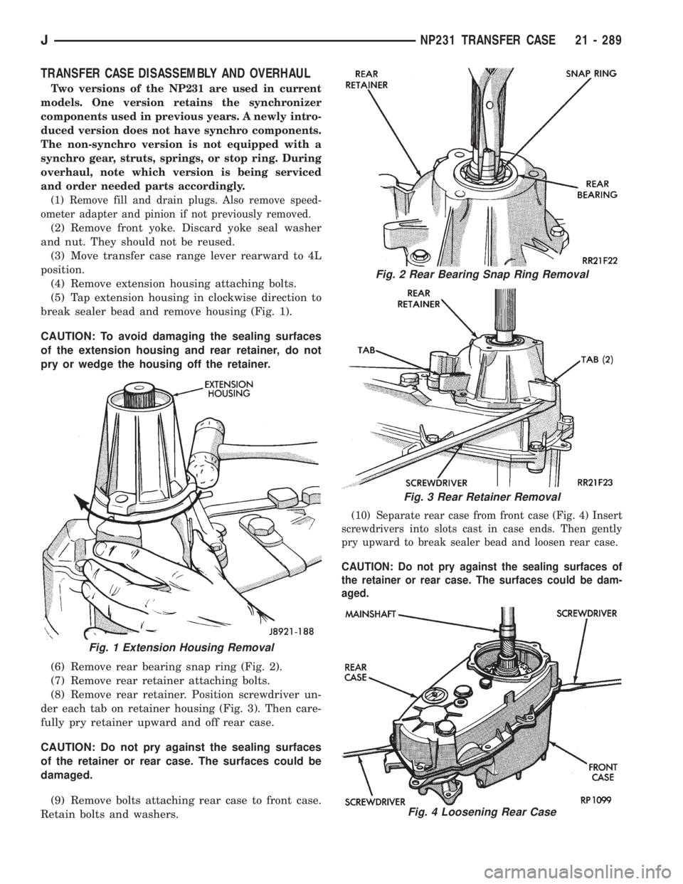
break sealer bead and remove housing (Fig. 1).
CAUTION: To avoid damaging the sealing surfaces
of the extension housing and rear retainer, do not
pry or wedge the housing off the retainer.
(6) Remove rear bearing snap ring (Fig. 2).
(7) Remove rear retainer attaching bolts.
(8) Remove rear retainer. Position screwdriver un-
der each tab on retainer housing (Fig. 3). Then care-
fully pry retainer upward and off rear case.
CAUTION: Do not pry against the sealing surfaces
of the retainer or rear case. The surfaces could be
damaged.
(9) Remove bolts attaching rear case to front case.
Retain bolts and washers.
(10) Separate rear case from front case (Fig. 4) Insert
screwdrivers into slots cast in case ends. Then gently
pry upward to break sealer bead and loosen rear case.
CAUTION: Do not pry against the sealing surfaces of
the retainer or rear case. The surfaces could be dam-
aged.
Fig. 1 Extension Housing Removal
Fig. 2 Rear Bearing Snap Ring Removal
Fig. 3 Rear Retainer Removal
Fig. 4 Loosening Rear Case
JNP231 TRANSFER CASE 21 - 289
Page 1858 of 2158
(8) Remove input gear bearing from front case
with Tool Handle C-4171 and Tool C-4210, 7828, or
5062. Use tool that is best fit in bearing (Fig. 34).
(9) Turn front case over.
(10) Start bearing in case by hand. Then seat bear-
ing with Tools C-4171 and C-4210, or 7828 until snap
ring seats against case surface (Fig. 35).
INPUT AND LOW RANGE GEAR ASSEMBLY
AND INSTALLATION
(1) Remove mainshaft pilot bearing from input
gear with Tool MD-998346, or similar tool as follows:
(a) Turn puller tool bolt until jaws retract
enough to fit into bearing (Fig. 36).
(b) Insert puller bolt and jaws into bearing. Then
turn puller bolt clockwise so ramp on bolt spreads
jaws forcing them under bearing (Fig. 37).
Fig. 34 Input Gear Bearing Removal
Fig. 35 Input Gear Bearing Installation
Fig. 36 Puller Jaws In Retracted Position
Fig. 37 Puller Bolt And Jaws Seated Under Needle
Bearing
21 - 296 NP231 TRANSFER CASEJ
Page 1859 of 2158
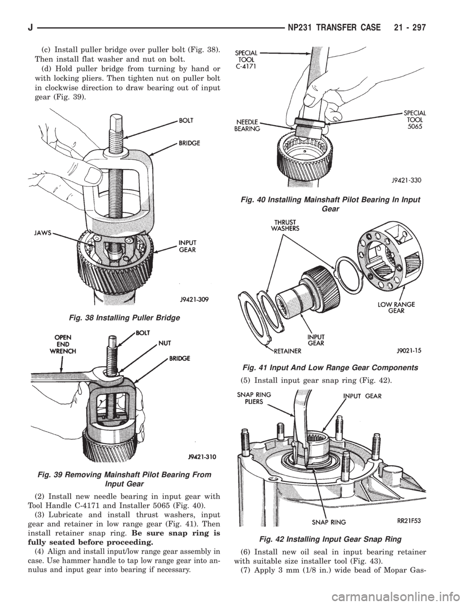
(c) Install puller bridge over puller bolt (Fig. 38).
Then install flat washer and nut on bolt.
(d) Hold puller bridge from turning by hand or
with locking pliers. Then tighten nut on puller bolt
in clockwise direction to draw bearing out of input
gear (Fig. 39).
(2) Install new needle bearing in input gear with
Tool Handle C-4171 and Installer 5065 (Fig. 40).
(3) Lubricate and install thrust washers, input
gear and retainer in low range gear (Fig. 41). Then
install retainer snap ring.Be sure snap ring is
fully seated before proceeding.
(4) Align and install input/low range gear assembly in
case. Use hammer handle to tap low range gear into an-
nulus and input gear into bearing if necessary.
(5) Install input gear snap ring (Fig. 42).
(6) Install new oil seal in input bearing retainer
with suitable size installer tool (Fig. 43).
(7) Apply 3 mm (1/8 in.) wide bead of Mopar Gas-
Fig. 38 Installing Puller Bridge
Fig. 39 Removing Mainshaft Pilot Bearing From
Input Gear
Fig. 40 Installing Mainshaft Pilot Bearing In Input
Gear
Fig. 41 Input And Low Range Gear Components
Fig. 42 Installing Input Gear Snap Ring
JNP231 TRANSFER CASE 21 - 297
Page 1872 of 2158
(6) Install vehicle speed sensor and adapter, if re-
moved. Then connect vehicle speed sensor wires, vent
hoses and electrical switch connector.
(7) Align and connect propeller shafts. Tighten
shaft U-joint clamp bolts to 19 Nzm (14 ft. lbs.)
torque.
(8) Fill transfer case with Mopar Dexron II. Cor-
rect fill level is to bottom edge of fill plug hole.
(9) Install rear crossmember. Tighten crossmember
bolts to 41 Nzm (30 ft. lbs.) torque.
(10) Remove transmission jack and transmission
support stand.
(11) Move transfer case range lever to 4L position.
(12) Connect shift rod to transfer case range lever.
(13) Adjust transfer case shift linkage as described
in this section.
(14) Lower vehicle.
TRANSFER CASE DISASSEMBLY AND OVERHAUL
(1) Remove fill and drain plugs.
(2) Remove front yoke. Discard yoke seal washer
and nut.
(3) Place transfer case range lever in 4L position.
(4) Remove extension housing attaching bolts.
(5) Tap extension housing in a clockwise direction
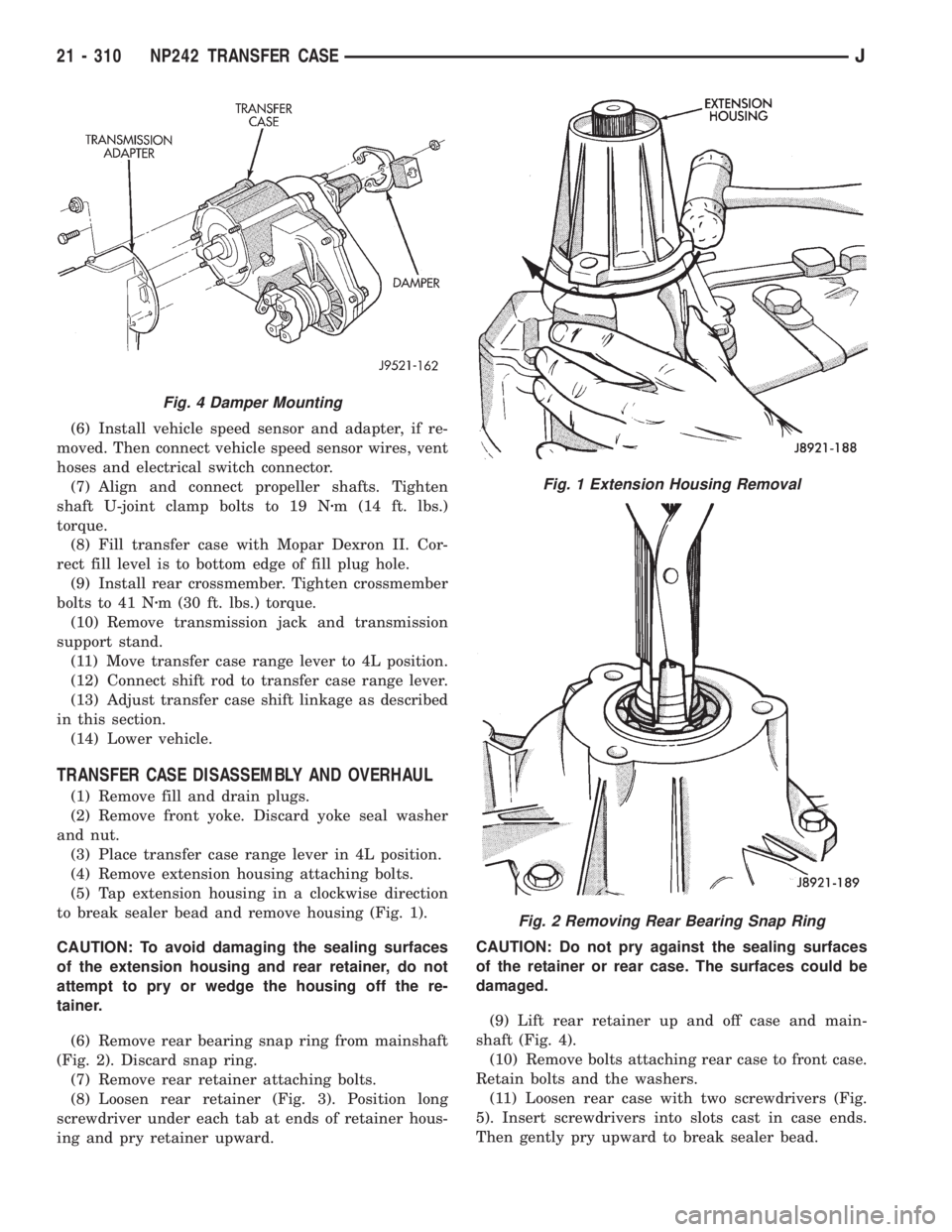
to break sealer bead and remove housing (Fig. 1).
CAUTION: To avoid damaging the sealing surfaces
of the extension housing and rear retainer, do not
attempt to pry or wedge the housing off the re-
tainer.
(6) Remove rear bearing snap ring from mainshaft
(Fig. 2). Discard snap ring.
(7) Remove rear retainer attaching bolts.
(8) Loosen rear retainer (Fig. 3). Position long
screwdriver under each tab at ends of retainer hous-
ing and pry retainer upward.CAUTION: Do not pry against the sealing surfaces
of the retainer or rear case. The surfaces could be
damaged.
(9) Lift rear retainer up and off case and main-
shaft (Fig. 4).
(10) Remove bolts attaching rear case to front case.
Retain bolts and the washers.
(11) Loosen rear case with two screwdrivers (Fig.
5). Insert screwdrivers into slots cast in case ends.
Then gently pry upward to break sealer bead.
Fig. 4 Damper Mounting
Fig. 1 Extension Housing Removal
Fig. 2 Removing Rear Bearing Snap Ring
21 - 310 NP242 TRANSFER CASEJ
Page 1875 of 2158
(20) Remove drive sprocket and chain (Fig. 11).
(21) Remove front output shaft (Fig. 12).(22) Remove transfer case shift lever nut and lever.
(23) Remove shift detent plug, spring and pin (Fig.
13)
(24) Remove seal plug from low range fork lockpin
access hole. Then move shift sector to align low range
fork lockpin with access hole (Fig. 14).
(25) Remove range fork lockpin with size number
one easy-out tool. Grip easy-out tool with locking pli-
ers and remove pin with counterclockwise, twist and
pull motion (Fig. 14).
fig. 11 Drive Sprocket And Chain Removal
Fig. 12 Removing Front Output Shaft
Fig. 13 Detent Component Removal
Fig. 14 Low Range Fork Lockpin Removal
JNP242 TRANSFER CASE 21 - 313
Page 1982 of 2158
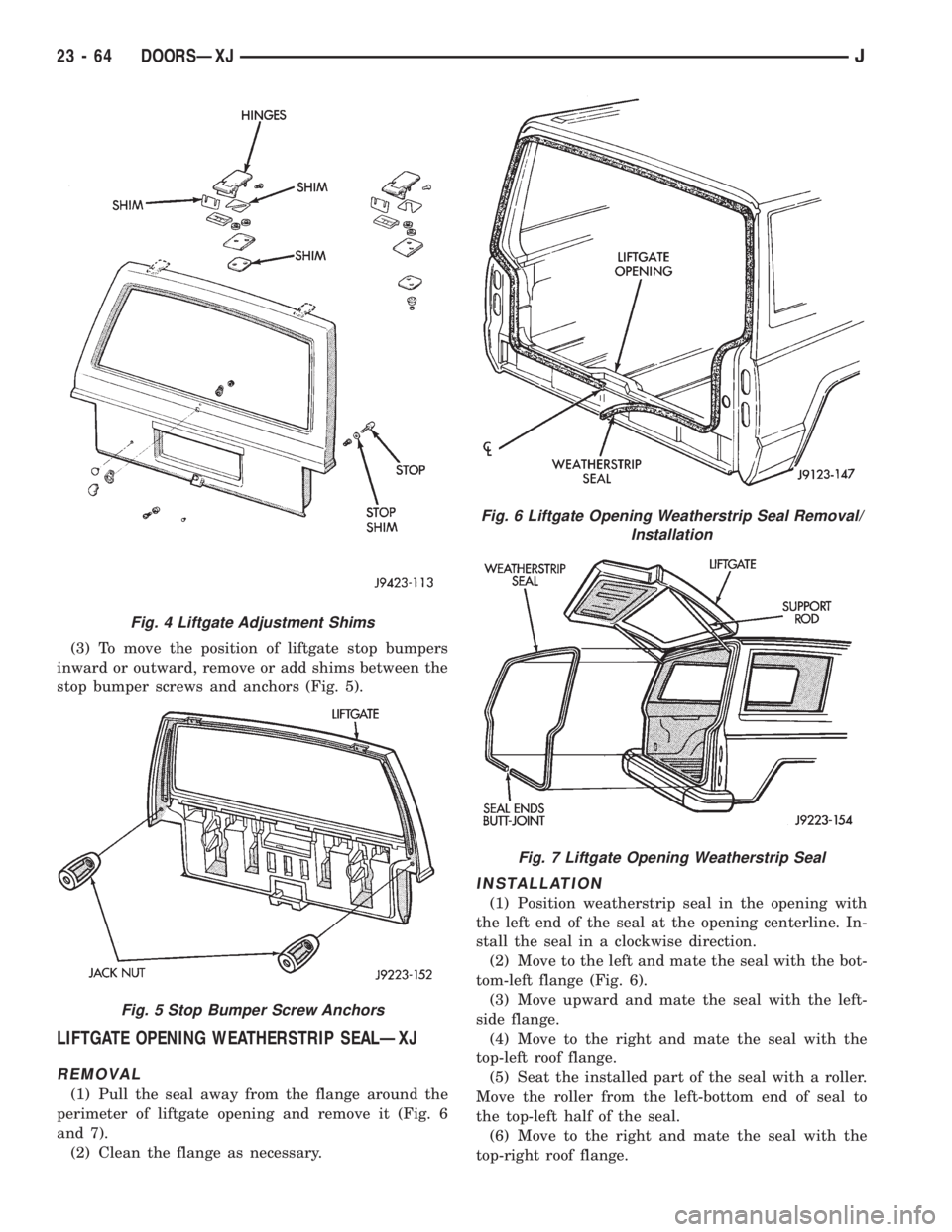
(3) To move the position of liftgate stop bumpers
inward or outward, remove or add shims between the
stop bumper screws and anchors (Fig. 5).
LIFTGATE OPENING WEATHERSTRIP SEALÐXJ
REMOVAL
(1) Pull the seal away from the flange around the
perimeter of liftgate opening and remove it (Fig. 6
and 7).
(2) Clean the flange as necessary.
INSTALLATION
(1) Position weatherstrip seal in the opening with
the left end of the seal at the opening centerline. In-
stall the seal in a clockwise direction.
(2) Move to the left and mate the seal with the bot-
tom-left flange (Fig. 6).
(3) Move upward and mate the seal with the left-
side flange.
(4) Move to the right and mate the seal with the
top-left roof flange.
(5) Seat the installed part of the seal with a roller.
Move the roller from the left-bottom end of seal to
the top-left half of the seal.
(6) Move to the right and mate the seal with the
top-right roof flange.
Fig. 4 Liftgate Adjustment Shims
Fig. 5 Stop Bumper Screw Anchors
Fig. 6 Liftgate Opening Weatherstrip Seal Removal/
Installation
Fig. 7 Liftgate Opening Weatherstrip Seal
23 - 64 DOORSÐXJJ