1995 JEEP YJ clock
[x] Cancel search: clockPage 1717 of 2158
justment must be performed properly and in the cor-
rect sequence. The correct sequence is line pressure
adjustment first and throttle pressure adjustment
last.
Line Pressure Adjustment
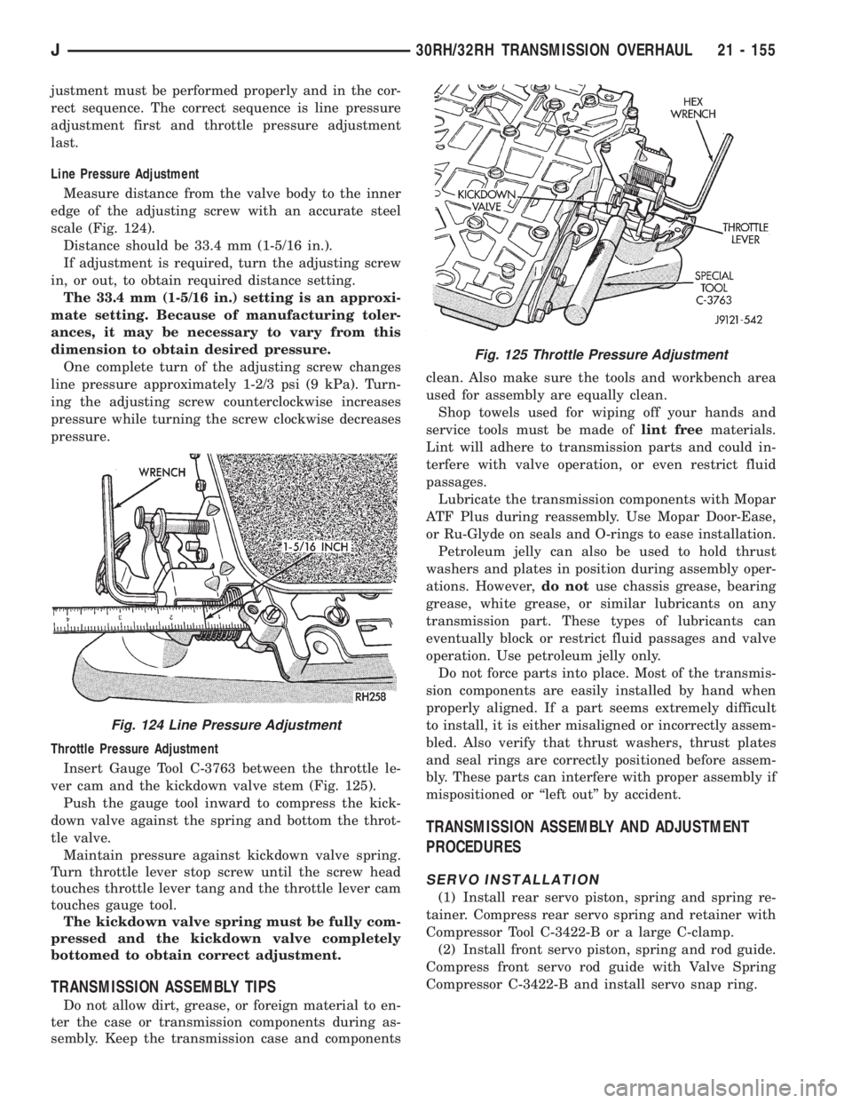
Measure distance from the valve body to the inner
edge of the adjusting screw with an accurate steel
scale (Fig. 124).
Distance should be 33.4 mm (1-5/16 in.).
If adjustment is required, turn the adjusting screw
in, or out, to obtain required distance setting.
The 33.4 mm (1-5/16 in.) setting is an approxi-
mate setting. Because of manufacturing toler-
ances, it may be necessary to vary from this
dimension to obtain desired pressure.
One complete turn of the adjusting screw changes
line pressure approximately 1-2/3 psi (9 kPa). Turn-
ing the adjusting screw counterclockwise increases
pressure while turning the screw clockwise decreases
pressure.
Throttle Pressure Adjustment
Insert Gauge Tool C-3763 between the throttle le-
ver cam and the kickdown valve stem (Fig. 125).
Push the gauge tool inward to compress the kick-
down valve against the spring and bottom the throt-
tle valve.
Maintain pressure against kickdown valve spring.
Turn throttle lever stop screw until the screw head
touches throttle lever tang and the throttle lever cam
touches gauge tool.
The kickdown valve spring must be fully com-
pressed and the kickdown valve completely
bottomed to obtain correct adjustment.
TRANSMISSION ASSEMBLY TIPS
Do not allow dirt, grease, or foreign material to en-
ter the case or transmission components during as-
sembly. Keep the transmission case and componentsclean. Also make sure the tools and workbench area
used for assembly are equally clean.
Shop towels used for wiping off your hands and
service tools must be made oflint freematerials.
Lint will adhere to transmission parts and could in-
terfere with valve operation, or even restrict fluid
passages.
Lubricate the transmission components with Mopar
ATF Plus during reassembly. Use Mopar Door-Ease,
or Ru-Glyde on seals and O-rings to ease installation.
Petroleum jelly can also be used to hold thrust
washers and plates in position during assembly oper-
ations. However,do notuse chassis grease, bearing
grease, white grease, or similar lubricants on any
transmission part. These types of lubricants can
eventually block or restrict fluid passages and valve
operation. Use petroleum jelly only.
Do not force parts into place. Most of the transmis-
sion components are easily installed by hand when
properly aligned. If a part seems extremely difficult
to install, it is either misaligned or incorrectly assem-
bled. Also verify that thrust washers, thrust plates
and seal rings are correctly positioned before assem-
bly. These parts can interfere with proper assembly if
mispositioned or ``left out'' by accident.
TRANSMISSION ASSEMBLY AND ADJUSTMENT
PROCEDURES
SERVO INSTALLATION
(1) Install rear servo piston, spring and spring re-
tainer. Compress rear servo spring and retainer with
Compressor Tool C-3422-B or a large C-clamp.
(2) Install front servo piston, spring and rod guide.
Compress front servo rod guide with Valve Spring
Compressor C-3422-B and install servo snap ring.
Fig. 124 Line Pressure Adjustment
Fig. 125 Throttle Pressure Adjustment
J30RH/32RH TRANSMISSION OVERHAUL 21 - 155
Page 1719 of 2158
The 32RH transmission has a double wrap band, a
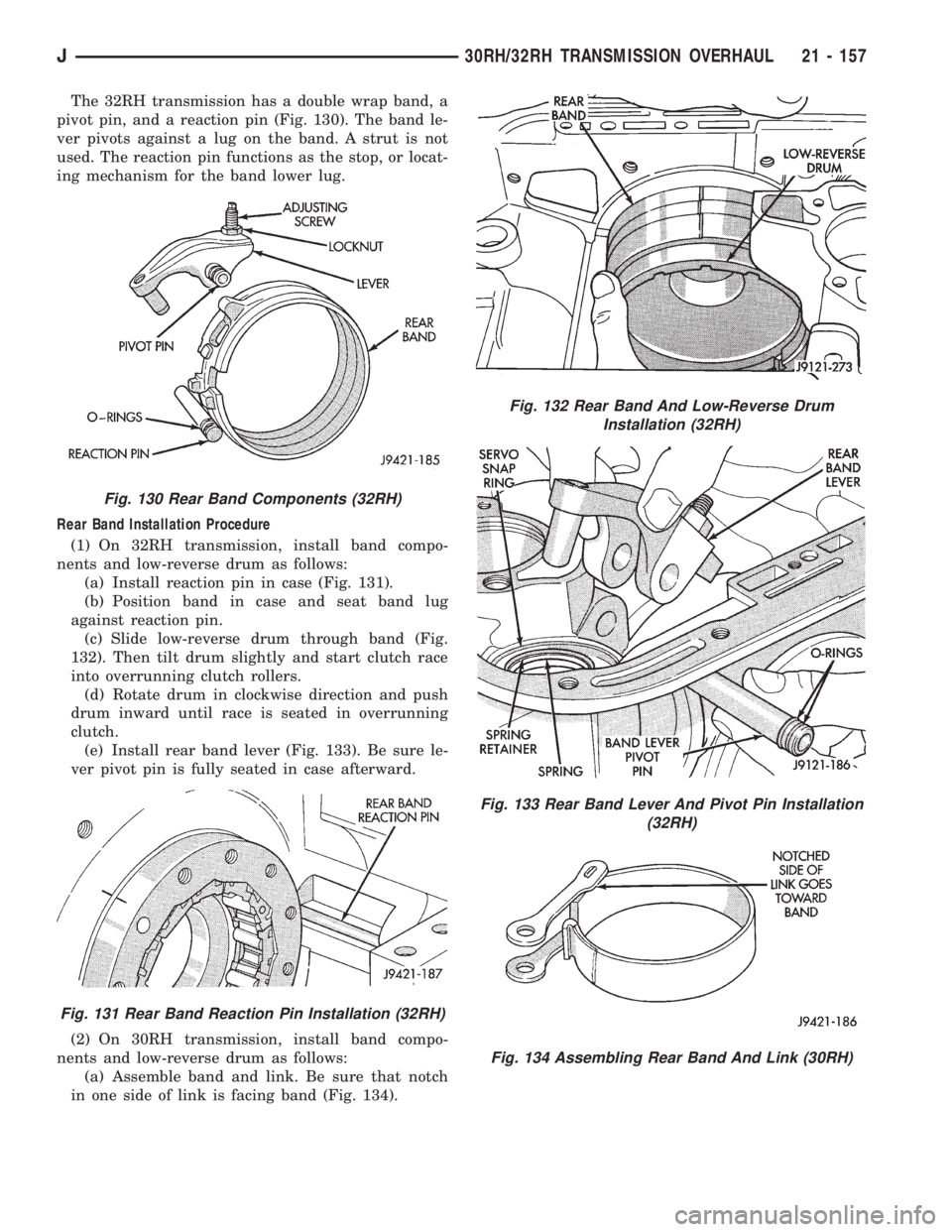
pivot pin, and a reaction pin (Fig. 130). The band le-
ver pivots against a lug on the band. A strut is not
used. The reaction pin functions as the stop, or locat-
ing mechanism for the band lower lug.
Rear Band Installation Procedure
(1) On 32RH transmission, install band compo-
nents and low-reverse drum as follows:
(a) Install reaction pin in case (Fig. 131).
(b) Position band in case and seat band lug
against reaction pin.
(c) Slide low-reverse drum through band (Fig.
132). Then tilt drum slightly and start clutch race
into overrunning clutch rollers.
(d) Rotate drum in clockwise direction and push
drum inward until race is seated in overrunning
clutch.
(e) Install rear band lever (Fig. 133). Be sure le-
ver pivot pin is fully seated in case afterward.
(2) On 30RH transmission, install band compo-
nents and low-reverse drum as follows:
(a) Assemble band and link. Be sure that notch
in one side of link is facing band (Fig. 134).
Fig. 130 Rear Band Components (32RH)
Fig. 131 Rear Band Reaction Pin Installation (32RH)
Fig. 132 Rear Band And Low-Reverse Drum
Installation (32RH)
Fig. 133 Rear Band Lever And Pivot Pin Installation
(32RH)
Fig. 134 Assembling Rear Band And Link (30RH)
J30RH/32RH TRANSMISSION OVERHAUL 21 - 157
Page 1720 of 2158
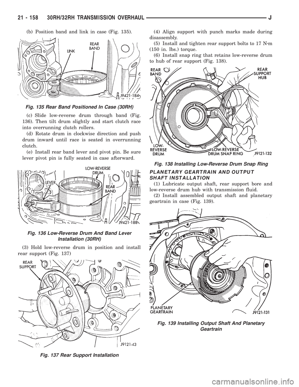
(b) Position band and link in case (Fig. 135).
(c) Slide low-reverse drum through band (Fig.
136). Then tilt drum slightly and start clutch race
into overrunning clutch rollers.
(d) Rotate drum in clockwise direction and push
drum inward until race is seated in overrunning
clutch.
(e) Install rear band lever and pivot pin. Be sure
lever pivot pin is fully seated in case afterward.
(3) Hold low-reverse drum in position and install
rear support (Fig. 137)(4) Align support with punch marks made during
disassembly.
(5) Install and tighten rear support bolts to 17 Nzm
(150 in. lbs.) torque.
(6) Install snap ring that retains low-reverse drum
to hub of rear support (Fig. 138).
PLANETARY GEARTRAIN AND OUTPUT
SHAFT INSTALLATION
(1) Lubricate output shaft, rear support bore and
low-reverse drum hub with transmission fluid.
(2) Install assembled output shaft and planetary
geartrain in case (Fig. 139).
Fig. 135 Rear Band Positioned In Case (30RH)
Fig. 136 Low-Reverse Drum And Band Lever
Installation (30RH)
Fig. 137 Rear Support Installation
Fig. 138 Installing Low-Reverse Drum Snap Ring
Fig. 139 Installing Output Shaft And Planetary
Geartrain
21 - 158 30RH/32RH TRANSMISSION OVERHAULJ
Page 1761 of 2158
TORQUE CONVERTER STATOR CLUTCH
INSPECTION
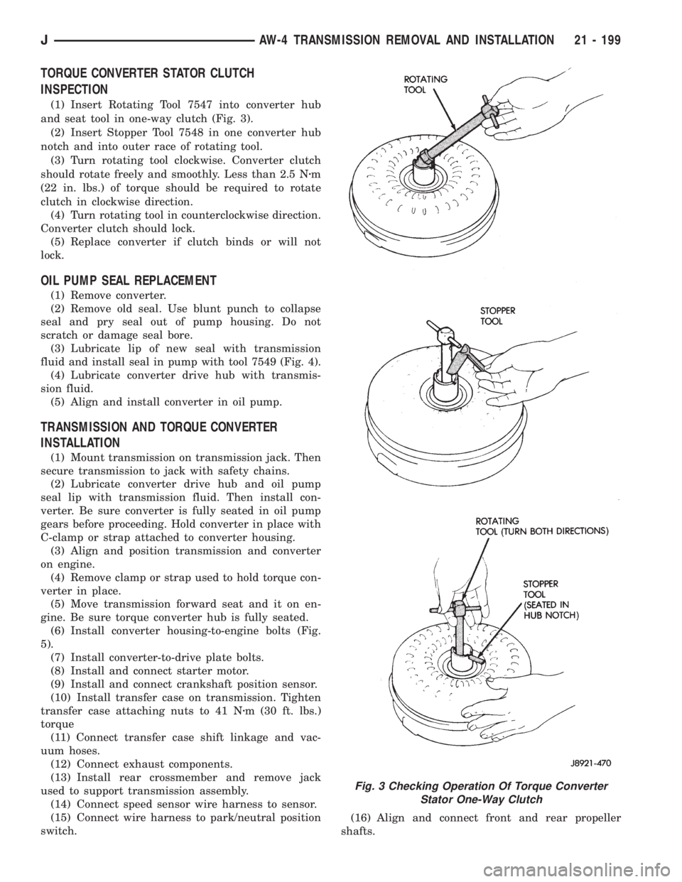
(1) Insert Rotating Tool 7547 into converter hub
and seat tool in one-way clutch (Fig. 3).
(2) Insert Stopper Tool 7548 in one converter hub
notch and into outer race of rotating tool.
(3) Turn rotating tool clockwise. Converter clutch
should rotate freely and smoothly. Less than 2.5 Nzm
(22 in. lbs.) of torque should be required to rotate
clutch in clockwise direction.
(4) Turn rotating tool in counterclockwise direction.
Converter clutch should lock.
(5) Replace converter if clutch binds or will not
lock.
OIL PUMP SEAL REPLACEMENT
(1) Remove converter.
(2) Remove old seal. Use blunt punch to collapse
seal and pry seal out of pump housing. Do not
scratch or damage seal bore.
(3) Lubricate lip of new seal with transmission
fluid and install seal in pump with tool 7549 (Fig. 4).
(4) Lubricate converter drive hub with transmis-
sion fluid.
(5) Align and install converter in oil pump.
TRANSMISSION AND TORQUE CONVERTER
INSTALLATION
(1) Mount transmission on transmission jack. Then
secure transmission to jack with safety chains.
(2) Lubricate converter drive hub and oil pump
seal lip with transmission fluid. Then install con-
verter. Be sure converter is fully seated in oil pump
gears before proceeding. Hold converter in place with
C-clamp or strap attached to converter housing.
(3) Align and position transmission and converter
on engine.
(4) Remove clamp or strap used to hold torque con-
verter in place.
(5) Move transmission forward seat and it on en-
gine. Be sure torque converter hub is fully seated.
(6) Install converter housing-to-engine bolts (Fig.
5).
(7) Install converter-to-drive plate bolts.
(8) Install and connect starter motor.
(9) Install and connect crankshaft position sensor.
(10) Install transfer case on transmission. Tighten
transfer case attaching nuts to 41 Nzm (30 ft. lbs.)
torque
(11) Connect transfer case shift linkage and vac-
uum hoses.
(12) Connect exhaust components.
(13) Install rear crossmember and remove jack
used to support transmission assembly.
(14) Connect speed sensor wire harness to sensor.
(15) Connect wire harness to park/neutral position
switch.(16) Align and connect front and rear propeller
shafts.
Fig. 3 Checking Operation Of Torque Converter
Stator One-Way Clutch
JAW-4 TRANSMISSION REMOVAL AND INSTALLATION 21 - 199
Page 1780 of 2158
(13) Install pump in torque converter and check
pump gear rotation. Gears must rotate smoothly
when turned clockwise and counterclockwise.
(14) Lubricate pump O-ring and seal rings with pe-
troleum jelly.
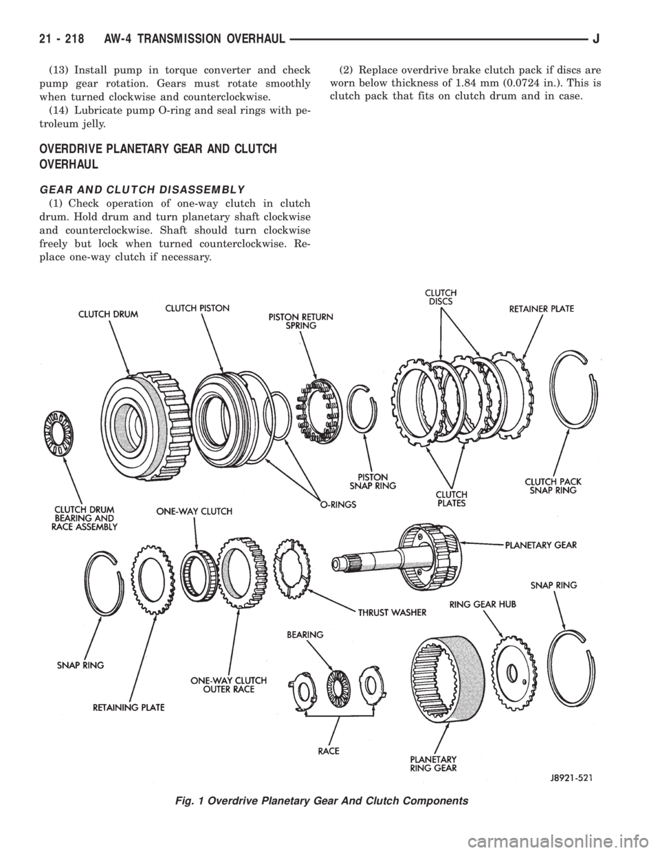
OVERDRIVE PLANETARY GEAR AND CLUTCH
OVERHAUL
GEAR AND CLUTCH DISASSEMBLY
(1) Check operation of one-way clutch in clutch
drum. Hold drum and turn planetary shaft clockwise
and counterclockwise. Shaft should turn clockwise
freely but lock when turned counterclockwise. Re-
place one-way clutch if necessary.(2) Replace overdrive brake clutch pack if discs are
worn below thickness of 1.84 mm (0.0724 in.). This is
clutch pack that fits on clutch drum and in case.
Fig. 1 Overdrive Planetary Gear And Clutch Components
21 - 218 AW-4 TRANSMISSION OVERHAULJ
Page 1787 of 2158
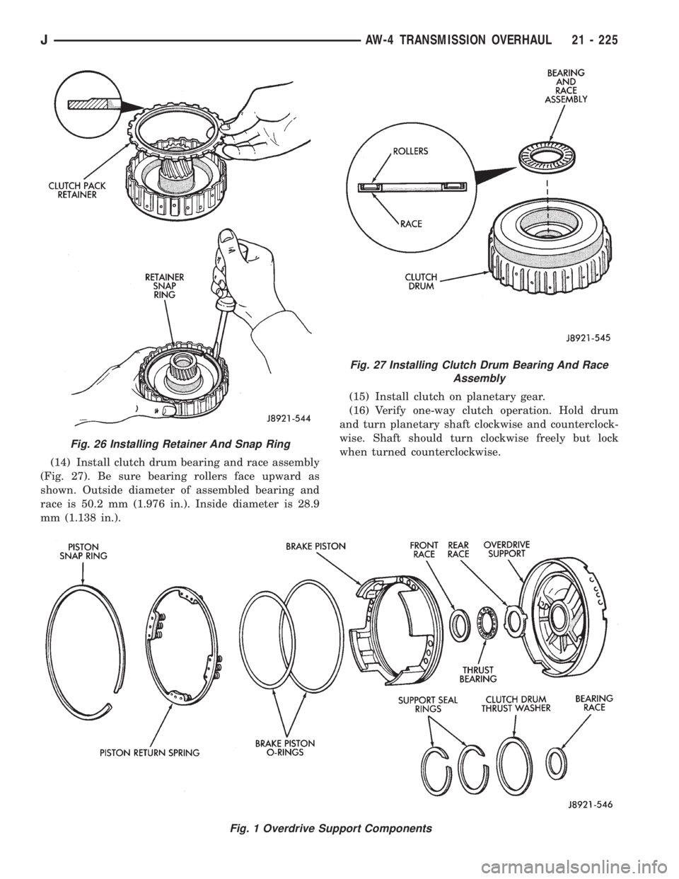
(14) Install clutch drum bearing and race assembly
(Fig. 27). Be sure bearing rollers face upward as
shown. Outside diameter of assembled bearing and
race is 50.2 mm (1.976 in.). Inside diameter is 28.9
mm (1.138 in.).(15) Install clutch on planetary gear.
(16) Verify one-way clutch operation. Hold drum
and turn planetary shaft clockwise and counterclock-
wise. Shaft should turn clockwise freely but lock
when turned counterclockwise.
Fig. 1 Overdrive Support Components
Fig. 26 Installing Retainer And Snap Ring
Fig. 27 Installing Clutch Drum Bearing And Race
Assembly
JAW-4 TRANSMISSION OVERHAUL 21 - 225
Page 1800 of 2158
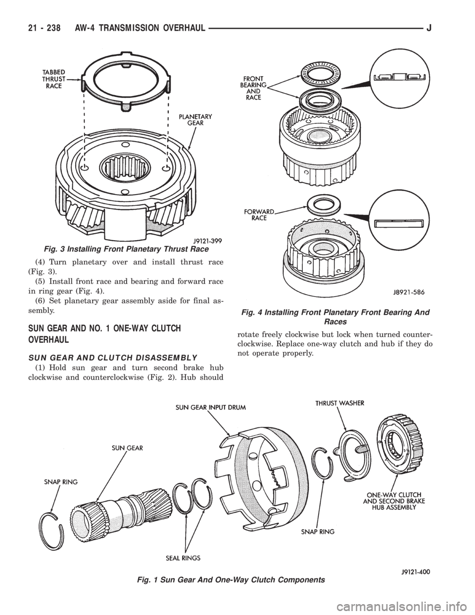
(4) Turn planetary over and install thrust race
(Fig. 3).
(5) Install front race and bearing and forward race
in ring gear (Fig. 4).
(6) Set planetary gear assembly aside for final as-
sembly.
SUN GEAR AND NO. 1 ONE-WAY CLUTCH
OVERHAUL
SUN GEAR AND CLUTCH DISASSEMBLY
(1) Hold sun gear and turn second brake hub
clockwise and counterclockwise (Fig. 2). Hub shouldrotate freely clockwise but lock when turned counter-
clockwise. Replace one-way clutch and hub if they do
not operate properly.
Fig. 3 Installing Front Planetary Thrust Race
Fig. 1 Sun Gear And One-Way Clutch Components
Fig. 4 Installing Front Planetary Front Bearing And
Races
21 - 238 AW-4 TRANSMISSION OVERHAULJ
Page 1802 of 2158
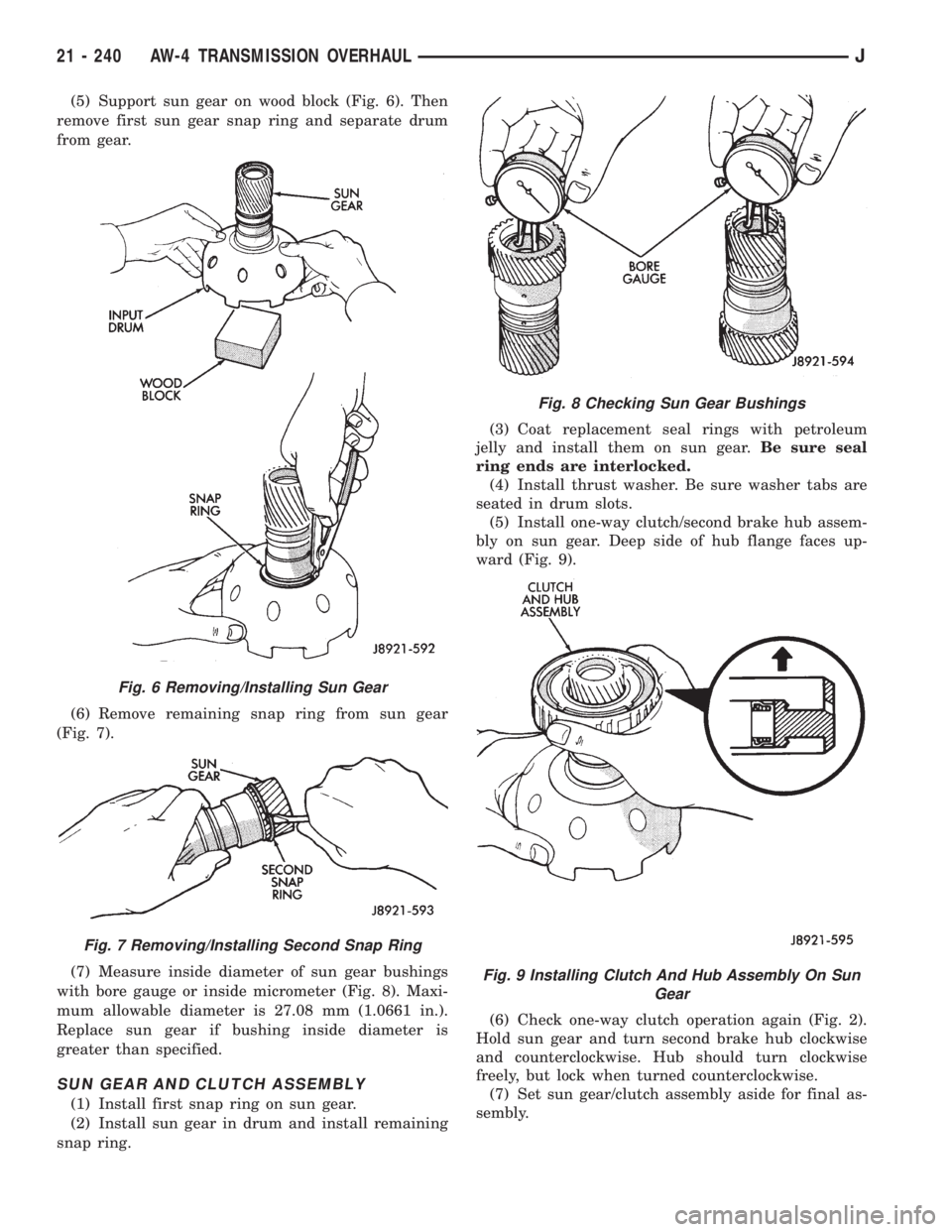
(5) Support sun gear on wood block (Fig. 6). Then
remove first sun gear snap ring and separate drum
from gear.
(6) Remove remaining snap ring from sun gear
(Fig. 7).
(7) Measure inside diameter of sun gear bushings
with bore gauge or inside micrometer (Fig. 8). Maxi-
mum allowable diameter is 27.08 mm (1.0661 in.).
Replace sun gear if bushing inside diameter is
greater than specified.
SUN GEAR AND CLUTCH ASSEMBLY
(1) Install first snap ring on sun gear.
(2) Install sun gear in drum and install remaining
snap ring.(3) Coat replacement seal rings with petroleum
jelly and install them on sun gear.Be sure seal
ring ends are interlocked.
(4) Install thrust washer. Be sure washer tabs are
seated in drum slots.
(5) Install one-way clutch/second brake hub assem-
bly on sun gear. Deep side of hub flange faces up-
ward (Fig. 9).
(6) Check one-way clutch operation again (Fig. 2).
Hold sun gear and turn second brake hub clockwise
and counterclockwise. Hub should turn clockwise
freely, but lock when turned counterclockwise.
(7) Set sun gear/clutch assembly aside for final as-
sembly.
Fig. 6 Removing/Installing Sun Gear
Fig. 7 Removing/Installing Second Snap Ring
Fig. 8 Checking Sun Gear Bushings
Fig. 9 Installing Clutch And Hub Assembly On Sun
Gear
21 - 240 AW-4 TRANSMISSION OVERHAULJ