1995 JEEP YJ clock
[x] Cancel search: clockPage 654 of 2158
AUDIO SYSTEM
RADIO
When the ignition switch is in the ACCESSORY or
RUN position, it connects circuit A1 from fuse 6 in the
Power Distribution Center (PDC) to circuit A48. Cir-
cuit A48 powers circuit F85 through fuse 2 in the fuse
block. Circuit F85 powers the radio.
Circuit Z1 provides ground for the radio. The an-
tenna connects to the rear of the radio.
RADIO MEMORY
Circuit M1 from the Ignition Off Draw (IOD) fuse
(fuse 9) in the fuse block supplies power for the radio
memory. The IOD fuse is removed during vehicle
shipping to prevent excessive battery draw.
Circuit A6 from fuse 16 in the Power Distribution
Center (PDC) supplies voltage to fuse 9. Circuit A7
from fuse 3 in the PDC powers circuit A6 through
fuse 16. Circuits A6, A7 and M1 are HOT at all times.
RADIO ILLUMINATION
Circuit E2 supplies battery voltage to the radio
illumination lamps when the headlamps or parking
lamps are on and the dimmer switch is in the LOW or
ON positions.
Circuit X5 supplies battery voltage for the radio
clock and station frequency display. Circuit X5 origi-
nates at the radio illumination relay and is fed by
either circuit F85 or circuit E2 depending on the
switch position inside the relay.
When the headlamps and parking lamps are off, the
radio illumination relay is in its normal At Rest posi-
tion. In the At Rest position, the relay connects circuit
F85 from fuse 2 in the fuse block to circuit X5.
When the headlamps or parking lamps are on, cir-
cuit L90 from the headlamp switch supplies battery
voltage to the coil side of the radio illumination relay.
Circuit Z1 provides ground for the coil side of the
relay.
When voltage is present on circuit L90, the radio
illumination relay switches from its At Rest position
to connect circuit E2 to circuit X5.
SPEAKERS
There are 3 different radio packages. The standard
radio package includes 2 speakers; one in each front
door. The four speaker system uses speakers in each
front door plus speakers in the rear sound bar. The six
speaker system has the front door speakers, sound bar
speakers and two speakers in the instrument panel.
BASE RADIO
Vehicles with the base radio have a jumper between
the radio and the instrument panel connectors. The
jumper simulates rear speaker load.Circuit X53 feeds the speaker in the left front door.
Circuit X55 is the return from the speaker to the
radio.
Circuit X54 feeds the right front door speaker. Cir-
cuit X56 is the return from the speaker to the radio.
FOUR SPEAKER SYSTEM
Circuit X53 feeds the speaker in the left front door.
Circuit X55 is the return from the speaker to the
radio.
Circuit X54 feeds the right front door speaker. Cir-
cuit X56 is the return from the speaker to the radio.
Circuit X51 feeds the left rear speaker. Circuit X57
is the return from the speaker to the radio.
Circuit X52 feeds the right rear speaker. Circuit
X58 is the return from the speaker to the radio.
SIX SPEAKER SYSTEM
Circuit X53 feeds the left speaker in the instrument
panel. The X53 circuit is double crimped at the in-
strument panel left speaker and branches to the left
front door speaker. Circuit X55 is the return to the
radio from the instrument panel left speaker and left
front door speaker. Circuit X55 is double crimped at
the instrument panel left speaker.
Circuit X54 feeds the right speaker in the instru-
ment panel. The X54 circuit is double crimped at the
instrument panel right speaker and branches to the
right front door speaker. Circuit X56 is the return to
the radio from the instrument panel left speaker and
left front door speaker. Circuit X56 is double crimped
at the instrument panel left speaker.
Circuit X51 feeds the left rear speaker. Circuit X57
is the return from the speaker to the radio.
Circuit X52 feeds the right rear speaker. Circuit
X58 is the return from the speaker to the radio.
DIAGRAM INDEX
Component Page
Fuse Block...........................8W-47-2, 3
Headlamp Switch.........................8W-47-2
Ignition Switch..........................8W-47-2
LCD Relay.............................8W-47-3
Power Distribution Center..................8W-47-2, 3
Radio............................8W-47-2 thru 7
Speakers (Six Speaker System)..............8W-47-4, 5
Speakers (Four Speaker System).............8W-47-6, 7
J8W-47 AUDIO SYSTEMÐXJ VEHICLES 8W -47 - 1
Page 923 of 2158

RADIO
RADIO
When the ignition switch is in the ACCESSORY or
RUN position, it connects circuit A1 from fuse 6 in
the Power Distribution Center (PDC) to circuit A48.
Circuit A48 powers circuit F85 through fuse 13 in the
fuse block. Circuit F85 powers the radio.
Circuit Z1 provides ground for the radio. The an-
tenna connects to the rear of the radio.
RADIO MEMORY
Circuit M1 from fuse 16 in the Power Distribution
Center (PDC) supplies power for the radio memory.
Circuit A7 from fuse 3 in the PDC supplies voltage
to fuse 16. Circuits A7 and M1 are HOT at all times.
RADIO ILLUMINATION
Circuit E2 supplies battery voltage to the radio il-
lumination lamps when the headlamps or parking
lamps are on and the dimmer switch is in the Low or
On positions.
Circuit X5 supplies battery voltage for the radio
clock and station frequency display. Circuit X5 origi-
nates at the radio illumination relay and is fed by ei-
ther circuit F85 or circuit E2 depending on the
switch position inside the relay.
When the headlamps and parking lamps are off,
the radio illumination relay is in its normal At Rest
position. In the At Rest position, the relay connects
circuit F85 from fuse 13 in the fuse block to circuit
X5.
When the headlamps or parking lamps are on, cir-
cuit L90 from the headlamp switch supplies battery
voltage to the coil side of the radio illumination relay.
Circuit Z1 provides ground for the coil side of the re-
lay.
When voltage is present on circuit L90, the radio
illumination relay switches from its At Rest position
to connect circuit E2 to circuit X5.
HELPFUL INFORMATION
²Circuit A48 supplies voltage to fuse 13 in the fuse
block for circuit F85 when the ignition switch is in
the ACCESSORY or RUN positions. In these posi-
tions, the ignition switch connects circuit A1 from
fuse 6 in the PDC to circuit A48.²Circuit A3 from fuse 5 in the PDC supplies power
to the fuse block for fuse 9. Fuse 9 protects circuit
L7. When the headlamps or parking lamps are ON,
the headlamp switch connects circuit L7 to circuit
L90. When the adjustable dimmer switch is in the
LOW to ON positions, it internally connects circuit
L7 to circuit E2. Circuit E2 powers fuse 25 in the
fuse block. Circuit E2 continues through fuse 25.
POWER ANTENNA
The Power Antenna Relay supplies power to raise
and lower the antenna. Circuit F60 from fuse 7 in
the fuse block powers the relay. Circuit Z1 provides
ground for the relay.
When the radio is turned on, circuit X60 from the
radio energizes the relay to raise the antenna.
SPEAKERS
Circuit X53 feeds the left front speakers. Circuit
X55 is the return from the speakers to the radio.
Circuit X54 feeds the right front speakers. Circuit
X56 is the return from the speakers to the radio.
Circuit X51 feeds the left rear speaker. Circuit X57
is the return from the speaker to the radio.
Circuit X52 feeds the right rear speaker. Circuit
X58 is the return from the speaker to the radio.
DIAGRAM INDEX
Component Page
Fuse 3 (PDC).........................8W-47-2, 4
Fuse 5 (PDC).......................8W-47-2, 4, 5
Fuse 6 (PDC).........................8W-47-2, 4
Fuse 7 (PDC).........................8W-47-2, 4
Fuse 9 (Fuse Block)...................8W-47-2, 4, 5
Fuse 13 (Fuse Block)....................8W-47-2, 4
Fuse 16 (PDC)........................8W-47-2, 4
Fuse 25 (Fuse Block)....................8W-47-2, 4
Headlamp Switch.......................8W-47-2, 4
Ignition Switch..........................8W-47-2
LCD Relay...........................8W-47-3, 5
Power Antenna..........................8W-47-6
Power Antenna Relay......................8W-47-6
Radio...........................8W-47-2 thru 8
Speakers............................8W-47-7, 8
J8W-47 AUDIO SYSTEMÐXJ-RHD 8W - 47 - 1
Page 1180 of 2158
RADIO
RADIO MEMORY
Circuit M1 from the Ignition Off Draw (IOD) fuse
in the Power Distribution Center (PDC) supplies
power for the radio memory. The IOD fuse is re-
moved during vehicle shipping to prevent excessive
battery draw.
Circuit A4 from fuse 8 in the PDC supplies voltage
to the IOD fuse in cavity 12. Circuit A4 is HOT at all
times.
RADIO ILLUMINATION
Circuit E2 supplies battery voltage to the radio il-
lumination lamps when the headlamps or parking
lamps are ON and the dimmer switch is in the LOW
or ON positions.
Circuit E22 supplies battery voltage for the radio
clock and station frequency display. Circuit E22 orig-
inates at the radio illumination relay and is fed by
either circuit F30 or circuit E2 depending on the
switch position inside the relay.
When the headlamps and parking lamps are OFF,
the radio illumination relay is in its normal At-Rest
position. In the At Rest position, the relay connects
circuit F30 from fuse 7 in the fuse block to circuit
E22.
When the headlamps or parking lamps are ON, cir-
cuit L7 from the headlamp switch supplies battery
voltage to the coil side of the radio illumination relay.
Circuit Z1 provides ground for the coil side of the re-
lay.
When voltage is present on circuit L7, the radio il-
lumination relay switches from its at rest position to
connect circuit E2 to circuit E22.
HELPFUL INFORMATION
²Circuit A31 supplies voltage to the fuse block for
circuit F30 when the ignition switch is in the AC-
CESSORY or RUN positions. In these positions the
ignition switch connects circuit A1 from fuse 4 in the
PDC to circuit A31. Circuit A31 powers a bus bar in
the fuse block that feeds circuit F30 through fuse 7.
²Circuit A6 from fuse 3 in the PDC supplies power
to the fuse block for fuse 8. Fuse 8 protects circuit
F33. When the headlamps or parking lamps are ON,the headlamp switch connects circuit F33 to circuit
L7. When the adjustable dimmer switch is in the
LOW to ON positions, it connects circuit L7 to circuit
E1. Circuit E1 powers fuse 10 in the fuse block. Fuse
10 in the fuse block protects circuit E2.
SPEAKERS
Circuit X53 feeds the speaker on the left side of the
instrument panel. Circuit X55 is the return from the
speaker to the radio.
Circuit X54 feeds the right instrument panel
speaker. Circuit X56 is the return from the speaker
to the radio.
The speaker feed and return circuits are double
crimped at the front speakers and continue to the
connector for the rear speakers. If the vehicle is not
equipped with the rear speaker sound bar, a jumper
is installed in the harness to simulate rear speaker
load.
Circuit X51 feeds the left rear speaker. Circuit X57
is the return from the speaker to the radio.
Circuit X52 feeds the right rear speaker. Circuit
X58 is the return from the speaker to the radio.
DIAGRAM INDEX
Component Page
Fuse 3 (PDC)...........................8W-47-3
Fuse 4 (PDC)...........................8W-47-2
Fuse 7 (Fuse Block).......................8W-47-2
Fuse 8 (Fuse Block).......................8W-47-3
Fuse 8 (PDC)...........................8W-47-2
Fuse 10 (Fuse Block)......................8W-47-3
Fuse 12 (PDC)..........................8W-47-2
Headlamp Switch.........................8W-47-3
Ignition Switch..........................8W-47-2
Left Front Speaker........................8W-47-4
Left Rear Speaker........................8W-47-5
Panel Lamp Dimmer Switch..................8W-47-3
Radio............................8W-47-2, 3, 4
Radio Illumination Relay....................8W-47-2
Right Front Speaker.......................8W-47-4
Right Rear Speaker.......................8W-47-5
J8W-47 AUDIO SYSTEMÐYJ VEHICLES 8W - 47 - 1
Page 1292 of 2158
2.5L ENGINE SERVICE PROCEDURES
INDEX
page page
Camshaft............................... 32
Camshaft Pin Replacement.................. 34
Engine AssemblyÐXJ Vehicles............... 18
Engine AssemblyÐYJ Vehicles............... 20
Engine Cylinder Head...................... 25
Engine Cylinder Head Cover................. 22
Engine Damper........................... 17
Engine MountÐRear....................... 16
Engine MountsÐFront..................... 14
General Information....................... 13
Hydraulic Tappets......................... 24OilPan ................................. 36
Rocker Arms and Push Rods................ 23
Timing Case Cover........................ 31
Timing Case Cover Oil Seal Replacement....... 30
Timing Chain and Sprockets................. 31
Valve Component ReplaceÐCylinder Head Not
Removed.............................. 23
Valve Springs and Oil Seals................. 23
Valve Timing............................. 30
Valves and Valve Springs................... 27
Vibration Damper......................... 30
GENERAL INFORMATION
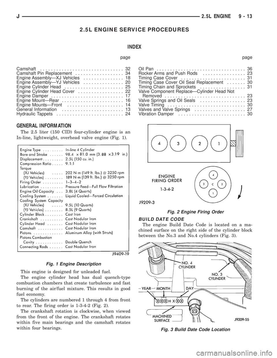
The 2.5 liter (150 CID) four-cylinder engine is an
In-line, lightweight, overhead valve engine (Fig. 1).
This engine is designed for unleaded fuel.
The engine cylinder head has dual quench-type
combustion chambers that create turbulence and fast
burning of the air/fuel mixture. This results in good
fuel economy.
The cylinders are numbered 1 through 4 from front
to rear. The firing order is 1-3-4-2 (Fig. 2).
The crankshaft rotation is clockwise, when viewed
from the front of the engine. The crankshaft rotates
within five main bearings and the camshaft rotates
within four bearings.
BUILD DATE CODE
The engine Build Date Code is located on a ma-
chined surface on the right side of the cylinder block
between the No.3 and No.4 cylinders (Fig. 3).
Fig. 1 Engine Description
Fig. 2 Engine Firing Order
Fig. 3 Build Date Code Location
J2.5L ENGINE 9 - 13
Page 1304 of 2158
LEAK-DOWN TEST
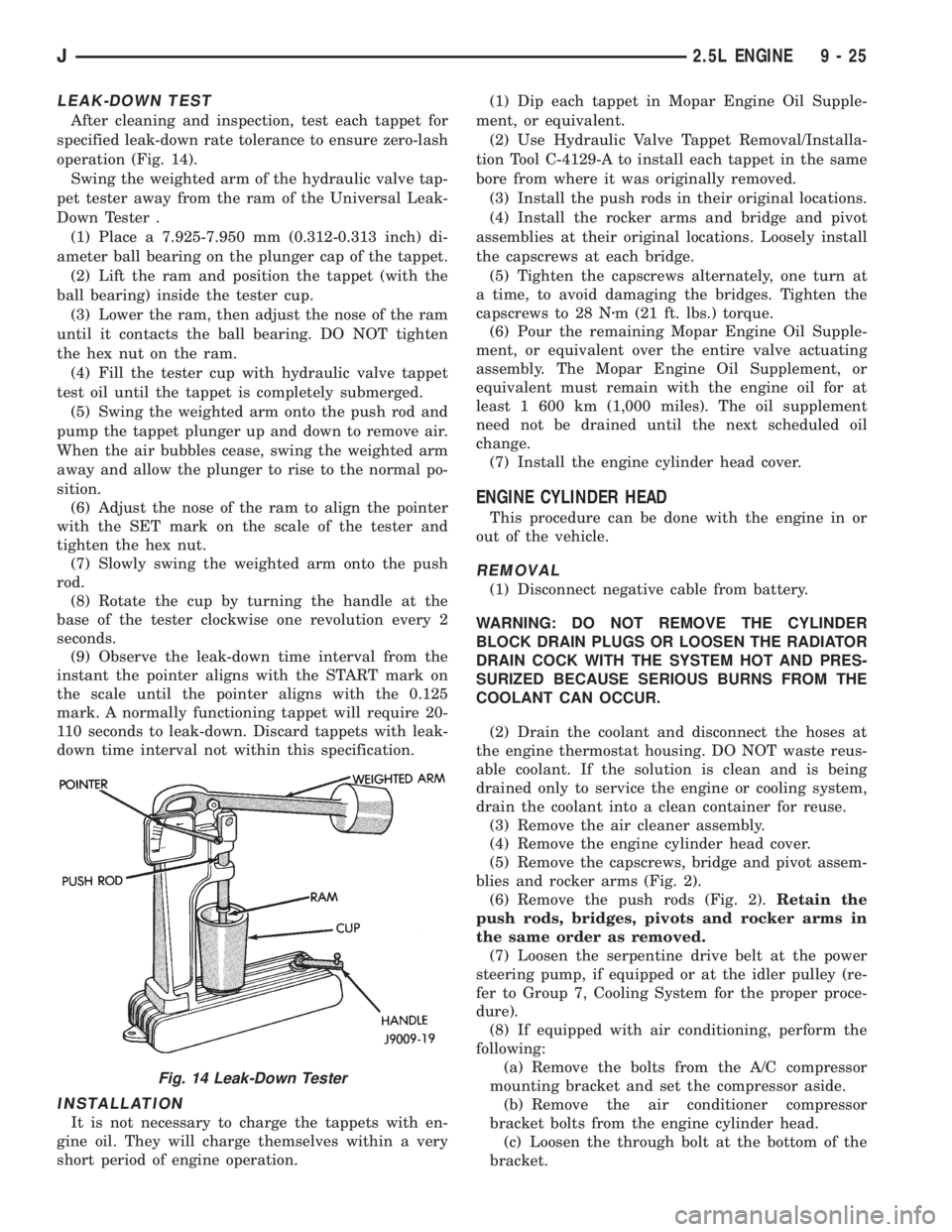
After cleaning and inspection, test each tappet for
specified leak-down rate tolerance to ensure zero-lash
operation (Fig. 14).
Swing the weighted arm of the hydraulic valve tap-
pet tester away from the ram of the Universal Leak-
Down Tester .
(1) Place a 7.925-7.950 mm (0.312-0.313 inch) di-
ameter ball bearing on the plunger cap of the tappet.
(2) Lift the ram and position the tappet (with the
ball bearing) inside the tester cup.
(3) Lower the ram, then adjust the nose of the ram
until it contacts the ball bearing. DO NOT tighten
the hex nut on the ram.
(4) Fill the tester cup with hydraulic valve tappet
test oil until the tappet is completely submerged.
(5) Swing the weighted arm onto the push rod and
pump the tappet plunger up and down to remove air.
When the air bubbles cease, swing the weighted arm
away and allow the plunger to rise to the normal po-
sition.
(6) Adjust the nose of the ram to align the pointer
with the SET mark on the scale of the tester and
tighten the hex nut.
(7) Slowly swing the weighted arm onto the push
rod.
(8) Rotate the cup by turning the handle at the
base of the tester clockwise one revolution every 2
seconds.
(9) Observe the leak-down time interval from the
instant the pointer aligns with the START mark on
the scale until the pointer aligns with the 0.125
mark. A normally functioning tappet will require 20-
110 seconds to leak-down. Discard tappets with leak-
down time interval not within this specification.
INSTALLATION
It is not necessary to charge the tappets with en-
gine oil. They will charge themselves within a very
short period of engine operation.(1) Dip each tappet in Mopar Engine Oil Supple-
ment, or equivalent.
(2) Use Hydraulic Valve Tappet Removal/Installa-
tion Tool C-4129-A to install each tappet in the same
bore from where it was originally removed.
(3) Install the push rods in their original locations.
(4) Install the rocker arms and bridge and pivot
assemblies at their original locations. Loosely install
the capscrews at each bridge.
(5) Tighten the capscrews alternately, one turn at
a time, to avoid damaging the bridges. Tighten the
capscrews to 28 Nzm (21 ft. lbs.) torque.
(6) Pour the remaining Mopar Engine Oil Supple-
ment, or equivalent over the entire valve actuating
assembly. The Mopar Engine Oil Supplement, or
equivalent must remain with the engine oil for at
least 1 600 km (1,000 miles). The oil supplement
need not be drained until the next scheduled oil
change.
(7) Install the engine cylinder head cover.
ENGINE CYLINDER HEAD
This procedure can be done with the engine in or
out of the vehicle.
REMOVAL
(1) Disconnect negative cable from battery.
WARNING: DO NOT REMOVE THE CYLINDER
BLOCK DRAIN PLUGS OR LOOSEN THE RADIATOR
DRAIN COCK WITH THE SYSTEM HOT AND PRES-
SURIZED BECAUSE SERIOUS BURNS FROM THE
COOLANT CAN OCCUR.
(2) Drain the coolant and disconnect the hoses at
the engine thermostat housing. DO NOT waste reus-
able coolant. If the solution is clean and is being
drained only to service the engine or cooling system,
drain the coolant into a clean container for reuse.
(3) Remove the air cleaner assembly.
(4) Remove the engine cylinder head cover.
(5) Remove the capscrews, bridge and pivot assem-
blies and rocker arms (Fig. 2).
(6) Remove the push rods (Fig. 2).Retain the
push rods, bridges, pivots and rocker arms in
the same order as removed.
(7) Loosen the serpentine drive belt at the power
steering pump, if equipped or at the idler pulley (re-
fer to Group 7, Cooling System for the proper proce-
dure).
(8) If equipped with air conditioning, perform the
following:
(a) Remove the bolts from the A/C compressor
mounting bracket and set the compressor aside.
(b) Remove the air conditioner compressor
bracket bolts from the engine cylinder head.
(c) Loosen the through bolt at the bottom of the
bracket.
Fig. 14 Leak-Down Tester
J2.5L ENGINE 9 - 25
Page 1309 of 2158
at the engine cylinder head. Also tap the top of the
retainer to seat the valve locks.
(8) Install the engine cylinder head.
VALVE TIMING
Disconnect the spark plug wires and remove the
spark plugs.
Remove the engine cylinder head cover.
Remove the capscrews, bridge and pivot assembly,
and rocker arms from above the No.1 cylinder.
Alternately loosen each capscrew, one turn at a
time, to avoid damaging the bridge.
Rotate the crankshaft until the No.4 piston is at
top dead center (TDC) on the compression stroke.
Rotate the crankshaft counterclockwise (viewed
from the front of the engine) 90É.
Install a dial indicator on the end of the No.1 cyl-
inder intake valve push rod. Use rubber tubing to se-
cure the indicator stem on the push rod.
Set the dial indicator pointer at zero.
Rotate the crankshaft clockwise (viewed from the
front of the engine) until the dial indicator pointer
indicates 0.305 mm (0.012 inch) travel distance (lift).
The timing notch index on the vibration damper
should be aligned with the TDC mark on the timing
degree scale.
If the timing notch is more than 13 mm (1/2 inch)
away from the TDC mark in either direction, the
valve timing is incorrect.
If the valve timing is incorrect, the cause may be a
broken camshaft pin. It is not necessary to replace
the camshaft because of pin failure. A spring pin is
available for service replacement.
VIBRATION DAMPER
REMOVAL
(1) Disconnect negative cable from battery.
(2) Remove the serpentine drive belt and fan
shroud.
(3) Remove the vibration damper retaining bolt
and washer.
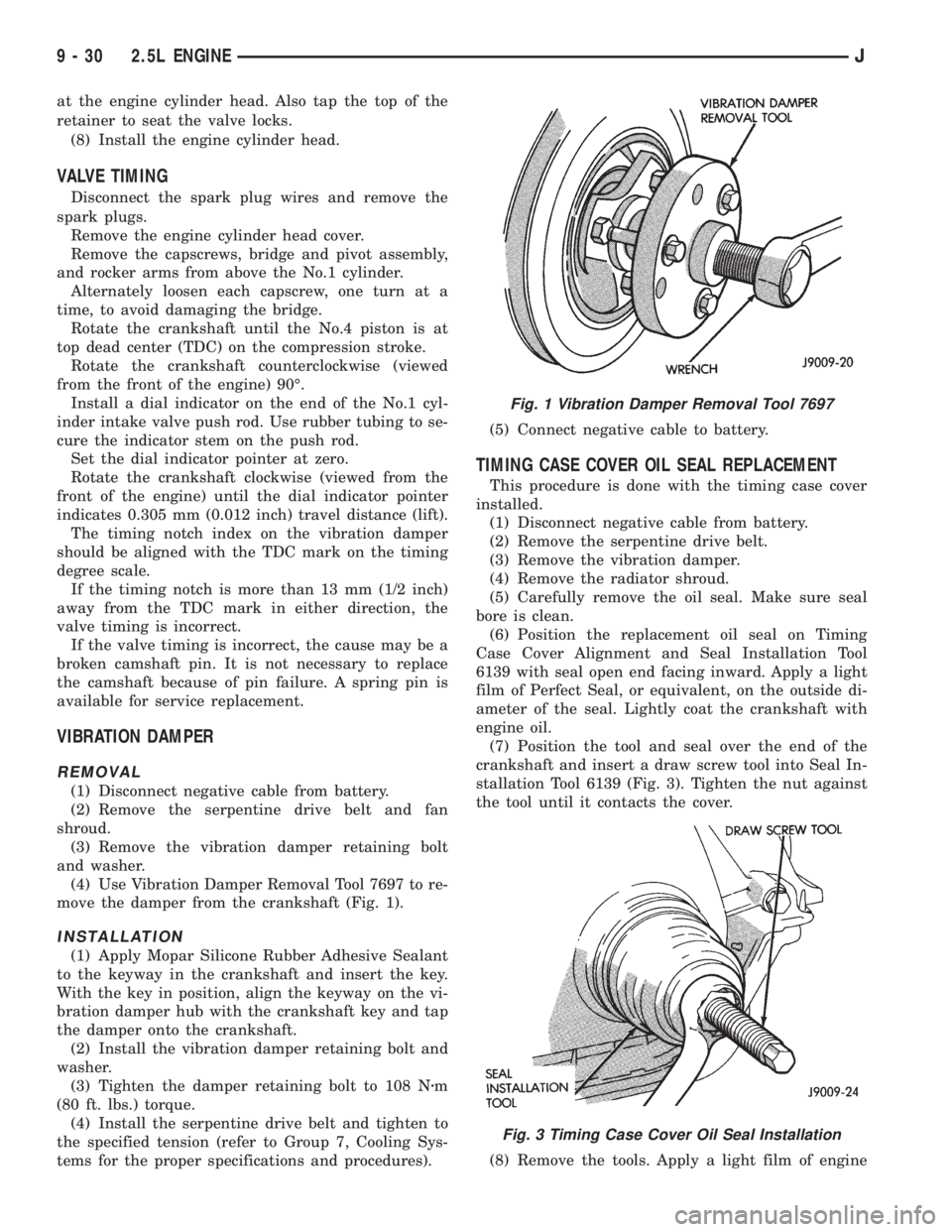
(4) Use Vibration Damper Removal Tool 7697 to re-
move the damper from the crankshaft (Fig. 1).
INSTALLATION
(1) Apply Mopar Silicone Rubber Adhesive Sealant
to the keyway in the crankshaft and insert the key.
With the key in position, align the keyway on the vi-
bration damper hub with the crankshaft key and tap
the damper onto the crankshaft.
(2) Install the vibration damper retaining bolt and
washer.
(3) Tighten the damper retaining bolt to 108 Nzm
(80 ft. lbs.) torque.
(4) Install the serpentine drive belt and tighten to
the specified tension (refer to Group 7, Cooling Sys-
tems for the proper specifications and procedures).(5) Connect negative cable to battery.
TIMING CASE COVER OIL SEAL REPLACEMENT
This procedure is done with the timing case cover
installed.
(1) Disconnect negative cable from battery.
(2) Remove the serpentine drive belt.
(3) Remove the vibration damper.
(4) Remove the radiator shroud.
(5) Carefully remove the oil seal. Make sure seal
bore is clean.
(6) Position the replacement oil seal on Timing
Case Cover Alignment and Seal Installation Tool
6139 with seal open end facing inward. Apply a light
film of Perfect Seal, or equivalent, on the outside di-
ameter of the seal. Lightly coat the crankshaft with
engine oil.
(7) Position the tool and seal over the end of the
crankshaft and insert a draw screw tool into Seal In-
stallation Tool 6139 (Fig. 3). Tighten the nut against
the tool until it contacts the cover.
(8) Remove the tools. Apply a light film of engine
Fig. 1 Vibration Damper Removal Tool 7697
Fig. 3 Timing Case Cover Oil Seal Installation
9 - 30 2.5L ENGINEJ
Page 1334 of 2158
4.0L ENGINE SERVICE PROCEDURES
INDEX
page page
Camshaft............................... 74
Camshaft Pin Replacement.................. 75
Engine AssemblyÐXJ Vehicles............... 59
Engine AssemblyÐYJ Vehicles............... 62
Engine Cylinder Head...................... 67
Engine Cylinder Head Cover................. 64
Engine MountÐRear....................... 57
Engine MountsÐFront..................... 56
General Information....................... 55
Hydraulic Tappets......................... 66
OilPan ................................. 77Rocker Arms and Push Rods................ 65
Timing Case Cover........................ 72
Timing Case Cover Oil Seal Replacement....... 73
Timing Chain and Sprockets................. 73
Valve Component ReplaceÐCylinder Head Not
Removed.............................. 65
Valve Stem Seal and Spring Replacement....... 65
Valve Timing............................. 71
Valves and Valve Springs................... 69
Vibration Damper......................... 72
GENERAL INFORMATION
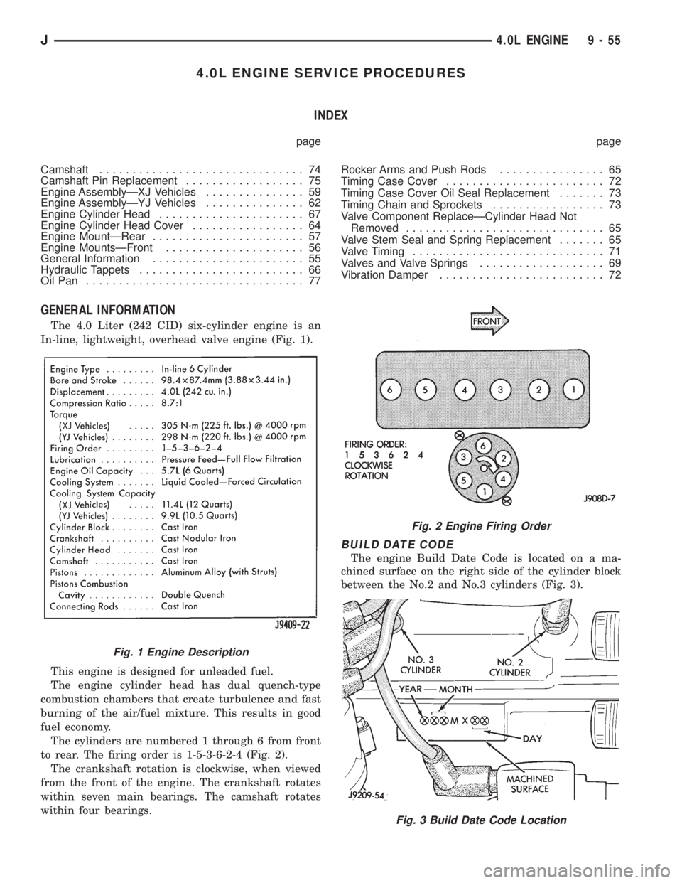
The 4.0 Liter (242 CID) six-cylinder engine is an
In-line, lightweight, overhead valve engine (Fig. 1).
This engine is designed for unleaded fuel.
The engine cylinder head has dual quench-type
combustion chambers that create turbulence and fast
burning of the air/fuel mixture. This results in good
fuel economy.
The cylinders are numbered 1 through 6 from front
to rear. The firing order is 1-5-3-6-2-4 (Fig. 2).
The crankshaft rotation is clockwise, when viewed
from the front of the engine. The crankshaft rotates
within seven main bearings. The camshaft rotates
within four bearings.
BUILD DATE CODE
The engine Build Date Code is located on a ma-
chined surface on the right side of the cylinder block
between the No.2 and No.3 cylinders (Fig. 3).
Fig. 1 Engine Description
Fig. 2 Engine Firing Order
Fig. 3 Build Date Code Location
J4.0L ENGINE 9 - 55
Page 1346 of 2158
LEAK-DOWN TEST
After cleaning and inspection, test each tappet for
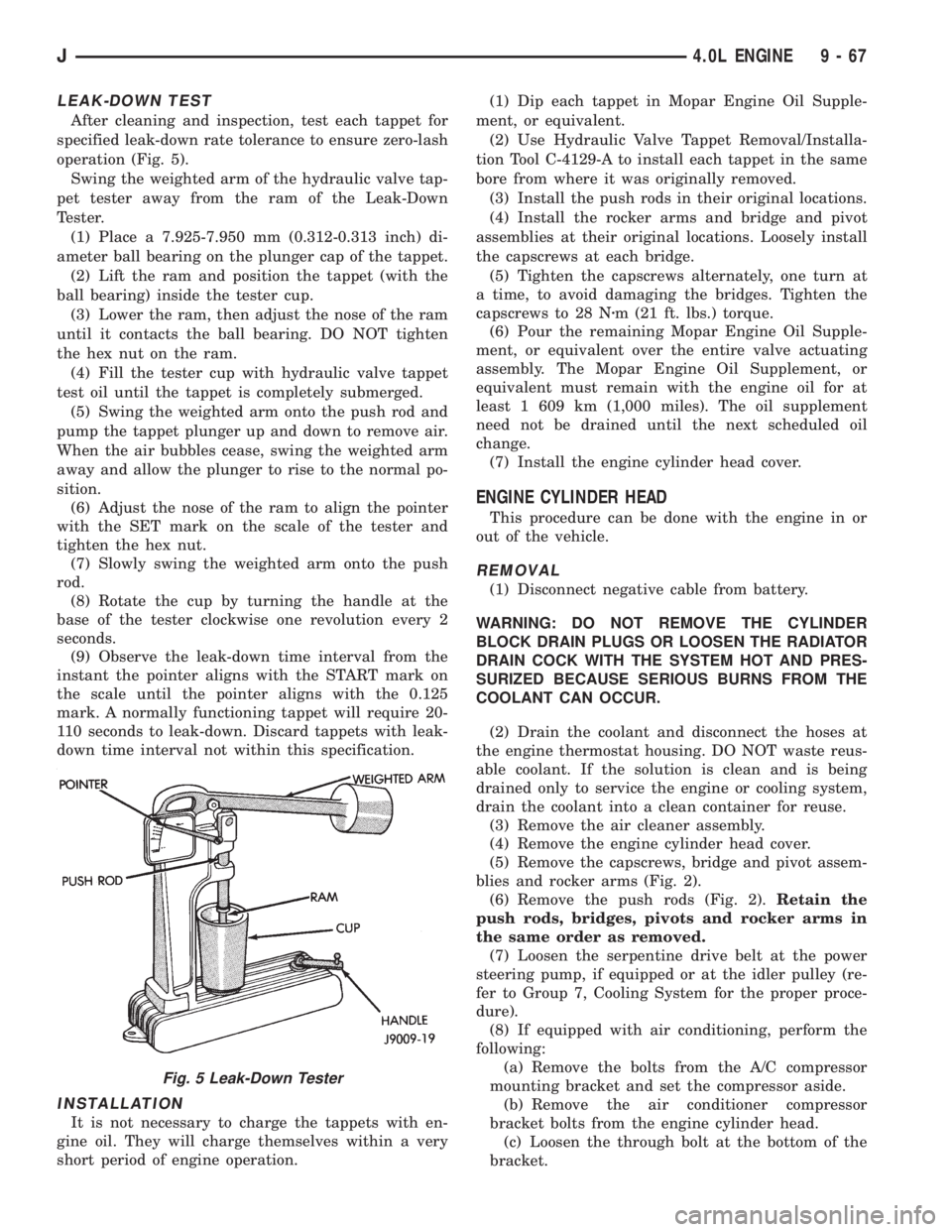
specified leak-down rate tolerance to ensure zero-lash
operation (Fig. 5).
Swing the weighted arm of the hydraulic valve tap-
pet tester away from the ram of the Leak-Down
Tester.
(1) Place a 7.925-7.950 mm (0.312-0.313 inch) di-
ameter ball bearing on the plunger cap of the tappet.
(2) Lift the ram and position the tappet (with the
ball bearing) inside the tester cup.
(3) Lower the ram, then adjust the nose of the ram
until it contacts the ball bearing. DO NOT tighten
the hex nut on the ram.
(4) Fill the tester cup with hydraulic valve tappet
test oil until the tappet is completely submerged.
(5) Swing the weighted arm onto the push rod and
pump the tappet plunger up and down to remove air.
When the air bubbles cease, swing the weighted arm
away and allow the plunger to rise to the normal po-
sition.
(6) Adjust the nose of the ram to align the pointer
with the SET mark on the scale of the tester and
tighten the hex nut.
(7) Slowly swing the weighted arm onto the push
rod.
(8) Rotate the cup by turning the handle at the
base of the tester clockwise one revolution every 2
seconds.
(9) Observe the leak-down time interval from the
instant the pointer aligns with the START mark on
the scale until the pointer aligns with the 0.125
mark. A normally functioning tappet will require 20-
110 seconds to leak-down. Discard tappets with leak-
down time interval not within this specification.
INSTALLATION
It is not necessary to charge the tappets with en-
gine oil. They will charge themselves within a very
short period of engine operation.(1) Dip each tappet in Mopar Engine Oil Supple-
ment, or equivalent.
(2) Use Hydraulic Valve Tappet Removal/Installa-
tion Tool C-4129-A to install each tappet in the same
bore from where it was originally removed.
(3) Install the push rods in their original locations.
(4) Install the rocker arms and bridge and pivot
assemblies at their original locations. Loosely install
the capscrews at each bridge.
(5) Tighten the capscrews alternately, one turn at
a time, to avoid damaging the bridges. Tighten the
capscrews to 28 Nzm (21 ft. lbs.) torque.
(6) Pour the remaining Mopar Engine Oil Supple-
ment, or equivalent over the entire valve actuating
assembly. The Mopar Engine Oil Supplement, or
equivalent must remain with the engine oil for at
least 1 609 km (1,000 miles). The oil supplement
need not be drained until the next scheduled oil
change.
(7) Install the engine cylinder head cover.
ENGINE CYLINDER HEAD
This procedure can be done with the engine in or
out of the vehicle.
REMOVAL
(1) Disconnect negative cable from battery.
WARNING: DO NOT REMOVE THE CYLINDER
BLOCK DRAIN PLUGS OR LOOSEN THE RADIATOR
DRAIN COCK WITH THE SYSTEM HOT AND PRES-
SURIZED BECAUSE SERIOUS BURNS FROM THE
COOLANT CAN OCCUR.
(2) Drain the coolant and disconnect the hoses at
the engine thermostat housing. DO NOT waste reus-
able coolant. If the solution is clean and is being
drained only to service the engine or cooling system,
drain the coolant into a clean container for reuse.
(3) Remove the air cleaner assembly.
(4) Remove the engine cylinder head cover.
(5) Remove the capscrews, bridge and pivot assem-
blies and rocker arms (Fig. 2).
(6) Remove the push rods (Fig. 2).Retain the
push rods, bridges, pivots and rocker arms in
the same order as removed.
(7) Loosen the serpentine drive belt at the power
steering pump, if equipped or at the idler pulley (re-
fer to Group 7, Cooling System for the proper proce-
dure).
(8) If equipped with air conditioning, perform the
following:
(a) Remove the bolts from the A/C compressor
mounting bracket and set the compressor aside.
(b) Remove the air conditioner compressor
bracket bolts from the engine cylinder head.
(c) Loosen the through bolt at the bottom of the
bracket.
Fig. 5 Leak-Down Tester
J4.0L ENGINE 9 - 67