1995 JEEP YJ body procedures
[x] Cancel search: body proceduresPage 479 of 2158

LAMPS
CONTENTS
page page
BULB APPLICATIONÐYJ VEHICLES......... 32
GENERAL INFORMATION................. 19INTERIOR LAMPS....................... 31
SERVICE PROCEDURES.................. 22
GENERAL INFORMATION
Each vehicle is equipped with various lamp assem-
blies. A good ground is necessary for proper lighting
operation. Grounding is provided by the lamp socket
when it comes in contact with the metal body, or
through a separate ground wire.
When changing lamp bulbs check the socket for
corrosion. If corrosion is present, clean it with a wire
brush and coat the inside of the socket lightly with
Mopar Multi-Purpose Grease or equivalent.
DIAGNOSTIC PROCEDURESÐYJ
When a vehicle experiences problems with the
headlamp system, verify the condition of the batteryconnections, charging system, headlamp bulbs, wire
connectors, relay, high beam dimmer switch and
headlamp switch. Refer to Group 8W, Wiring Dia-
grams for component locations and circuit informa-
tion.
Always begin any diagnosis by testing all of the
fuses and circuit breakers in the system. Refer to
Group 8W, Wiring Diagrams.
JLAMPSÐYJ VEHICLES 8L - 19
Page 494 of 2158

the airbag cushion so it can discharge the gas it pro-
duces directly into the cushion. The protective cover
is fitted to the front of the airbag module and forms
a decorative cover in the center of the steering wheel.
Upon airbag deployment, this cover will split hori-
zontally.
STORAGE
The airbag module must be stored in its original,
special container until used for service. Also, it must
be stored in a clean, dry environment; away from
sources of extreme heat, sparks, and high electrical
energy. Always place or store the module on a surface
with the trim cover facing up to minimize movement
in case of accidental deployment.
IMPACT SENSOR/INFLATOR ASSEMBLY
The impact sensor/inflator assembly is mounted to
the back of the airbag module. It seals the hole in
the steering wheel side of the airbag cushion so that
gas produced in the inflator can be discharged di-
rectly into the cushion.
The impact sensor provides verification of the di-
rection and severity of the impact. A spherical sens-
ing mass housed in a cylinder will move forward and
rotate a D-shaft when the vehicle is subjected to a
frontal impact of sufficient severity. Airbag inflation
is designed to occur at a precisely calibrated vehicle
deceleration force, and is not linked to vehicle road
speed.The D-shaft retains two spring-loaded firing pins.
When a firing pin is released by the D-shaft, it
strikes and ignites a primer. The primer then reacts
with the pelletized, solid generant contained in the
inflator to produce the nitrogen gas that inflates the
airbag cushion.
ARMING/DISARMING MECHANISM
The steering wheel hub incorporates an airbag
arming/disarming mechanism and a specially de-
signed nut-blocker. The nut-blocker serves as a safety
to prevent removal of the airbag module until the
unit has been disarmed. A removable plastic cover
plug on the top, outer hub of the steering wheel al-
lows access to the arming screw.
When the airbag module is disarmed, the arming
screw extends upward from the steering wheel hub.
This will prevent installation of the plastic cover
plug. Also, the nut-blocker is retracted to allow ac-
cess to the two upper airbag module mounting nuts.
When the airbag module is armed, the plastic cover
plug will install flush with the outer surface of the
steering wheel hub. In addition, the nut-blocker will
prevent access to the two upper airbag module
mounting nuts.
DIAGNOSIS
This mechanical airbag system can not be diag-
nosed or repaired. The only serviced component is
the airbag module assembly. If the airbag module isdamaged in any way or deployed, it must be re-
placed.
SERVICE PROCEDURES
AIRBAG SYSTEM SERVICE (DEPLOYED)
Any vehicle which is to be returned to use after an
airbag deployment, must have the airbag module re-
placed. This is a one-time component and cannot be
reused.
AIRBAG MODULE HANDLING
UNDEPLOYED
At no time should any source of electricity be per-
mitted near the inflator on the back of the module.
When carrying an undeployed module, the trim cover
should be pointed away from the body to minimizeinjury in the event of accidental deployment. If the
module is placed on a bench or other surface, the
plastic trim cover should be face up to minimize
movement in case of accidental deployment.
In addition, the airbag module should be disarmed
whenever the steering wheel or steering column re-
quires service or removal. Failure to observe this
warning could result in accidental airbag deployment
and possible personal injury. Refer to Group 19 -
Steering for more service procedures on steering
wheel and steering column.
8M - 2 RESTRAINT SYSTEMSJ
Page 515 of 2158
SERVICE PROCEDURES
POWER SEAT SWITCH REMOVE/INSTALL
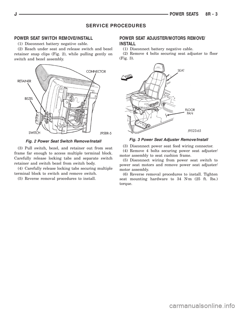
(1) Disconnect battery negative cable.
(2) Reach under seat and release switch and bezel
retainer snap clips (Fig. 2), while pulling gently on
switch and bezel assembly.
(3) Pull switch, bezel, and retainer out from seat
frame far enough to access multiple terminal block.
Carefully release locking tabs and separate switch
retainer and switch bezel from switch body.
(4) Carefully release locking tabs securing multiple
terminal block to switch and remove switch.
(5) Reverse removal procedures to install.
POWER SEAT ADJUSTER/MOTORS REMOVE/
INSTALL
(1) Disconnect battery negative cable.
(2) Remove 4 bolts securing seat adjuster to floor
(Fig. 3).
(3) Disconnect power seat feed wiring connector.
(4) Remove 4 bolts securing power seat adjuster/
motor assembly to seat cushion frame.
(5) Disconnect wiring from power seat switch to
power seat motors and remove power seat adjuster/
motor assembly.
(6) Reverse removal procedures to install. Tighten
seat mounting hardware to 34 Nzm (25 ft. lbs.)
torque.
Fig. 2 Power Seat Switch Remove/InstallFig. 3 Power Seat Adjuster Remove/Install
JPOWER SEATS 8R - 3
Page 517 of 2158
POWER WINDOWS
CONTENTS
page page
DIAGNOSIS............................. 1
GENERAL INFORMATION.................. 1SERVICE PROCEDURES................... 7
GENERAL INFORMATION
Power door windows are optional equipment on XJ
(Cherokee) models. The power windows operate only
with the ignition switch in the ON position. This
group covers diagnosis and service of the electrical
components peculiar to the power window system.
For service of mechanical components such as the
regulator, lift plate or window tracks refer to Group
23 - Body Components.
Following are general descriptions of the major
components in the power window system. Refer to
Group 8W - Wiring Diagrams for complete circuit de-
scriptions and diagrams.
POWER WINDOW SWITCH
Both front and rear door windows can be raised or
lowered electrically by operating the four two-way
switches on the driver's door panel. A single two-way
switch on each passenger's door panel operates only
the window on that passenger's door. The switches
cannot be repaired. If faulty, they must be replaced.
POWER WINDOW MOTOR
A permanent magnet reversible motor moves the
window regulator through a cable and drum operat-ing mechanism. A positive and negative battery con-
nection to the two motor terminals will cause the
motor to rotate in one direction. Reversing current
through these same two connections will cause the
motor to rotate in the opposite direction. In addition,
each power window motor is equipped with an inte-
gral automatic re-setting circuit breaker to protect
the motor from overloads. The power window motor
and regulator assembly cannot be repaired. If faulty,
the entire assembly must be replaced.
CIRCUIT BREAKER
An automatic re-setting circuit breaker in the fuse-
block module is used to protect the power window
system circuit. The circuit breaker can protect the
system from a short circuit, and can also protect the
system from an overload condition caused by an ob-
structed or stuck window glass or regulator. The cir-
cuit breaker can not be repaired. If faulty, it must be
replaced.
DIAGNOSIS
It is necessary that the window be free to slide up
and down for the power window system to function
properly. If the window is not free to move up and
down, the motor will overload and trip the circuit
breaker. To determine if the glass is free, disconnect
regulator plate from the glass and slide window up
and down by hand.
An alternate method is to shake the glass in the
door, with the glass positioned between the up and
down stop positions. Check that the glass can be
moved slightly from side to side, front to rear, and up
and down. Then check that window is not boundtight in the tracks. If window is free, proceed with di-
agnosis that follows. If window is not free, refer to
Group 23 - Body Components for service procedures.
CIRCUIT BREAKER
Locate correct circuit breaker in fuseblock module.
Pull out slightly, but be sure that circuit breaker ter-
minals still contact terminals in fuseblock module.
Turn ignition switch to ON position. Connect ground
wire of voltmeter to a good ground. With probe of
voltmeter positive lead, check both terminals of cir-
cuit breaker for battery voltage. If only one terminal
JPOWER WINDOWS 8S - 1
Page 531 of 2158
CHIME/BUZZER WARNING SYSTEMS
CONTENTS
page page
DIAGNOSIS............................. 2
GENERAL INFORMATION.................. 1SERVICE PROCEDURES................... 4
GENERAL INFORMATION
This group covers the buzzer warning system,
which is standard equipment on XJ (Cherokee)/YJ
(Wrangler) models. The system provides an audible
warning to the driver when it monitors the following
conditions:
²key is in ignition switch with the driver's door
open
²head or park lamps are on with driver's door open
(XJ only)
²driver's seat belt is not buckled with ignition
switch in ON position.
Following are general descriptions of the major
components in the buzzer warning system. Refer to
Group 8W - Wiring Diagrams for complete circuit de-
scriptions and diagrams.
BUZZER MODULE
The buzzer module is located in the fuseblock mod-
ule under the left end of the instrument panel. It re-
ceives battery voltage at all times from (fuse 15 - XJ,
fuse 3 - YJ) the fuseblock module. It also receives a
second battery feed (fuse 17 - XJ, fuse 9 - YJ) when
the ignition switch is in the ON or START position.
Other inputs to the module include the driver's door
jamb switch, the driver's seat belt switch, the ignition
key-in switch, and the headlamp switch (XJ only). The
only output of the module is a timed 4 to 8 second feed
to the seat belt reminder lamp in the message center of
the instrument cluster. The timer function begins after
the ignition switch is turned to the ON position.
The buzzer module can not be repaired. If faulty, it
must be replaced.
DRIVER'S DOOR JAMB SWITCH
The driver's door jamb switch is mounted to the
driver's door hinge pillar. The switch closes a path to
ground for the buzzer module through the key-in
switch or headlamp switch (XJ only) when the driv-
er's door is opened, and opens when the driver's door
is closed. This switch can not be repaired. If faulty, it
must be replaced.
IGNITION KEY-IN SWITCH
XJ MODELS
The key-in switch is integral to the ignition switch,
which is mounted on the right side of the steering col-
umn. It closes a path to ground for the buzzer module
when the ignition key is inserted in the ignition lock cyl-
inder and the driver's door jamb switch is closed (door
open). The switch opens when the key is removed from
the ignition lock cylinder. This switch can not be re-
paired. If faulty, the entire ignition switch must be re-
placed. Refer to Group 8D - Ignition Systems for service
procedures.
YJ MODELS
The key-in switch is mounted within the steering col-
umn in the lock cylinder housing. It closes a path to
ground for the buzzer module when the ignition key is
inserted in the ignition lock cylinder and the driver's
door jamb switch is closed (door open). The switch opens
when the key is removed from the ignition lock cylinder.
This switch is available for service replacement. Refer
to Group 19 - Steering for service procedures.
HEADLAMP SWITCH (XJ ONLY)
The headlamp switch is located in the instrument
panel. It closes a path to ground for the buzzer module
when the park or headlamps are on and the driver's
door jamb switch is closed (door open). The switch opens
the ground path when the park and headlamps are
turned off. The headlamp switch can not be repaired. If
faulty, it must be replaced. Refer to Group 8E - Instru-
ment Panel and Gauges for service procedures.
DRIVER'S SEAT BELT SWITCH
The driver's seat belt switch is integral to the driv-
er's seat belt buckle-half assembly. The switch is nor-
mally closed, providing a ground path to the buzzer
module. When the tip-half of the seat belt is inserted
into the seat belt buckle, the switch opens the buzzer
module ground path. The seat belt switch can not be
repaired. If faulty, the entire driver's seat belt buck-
le-half must be replaced. Refer to Group 23 - Body
Components for service procedures.
JCHIME/BUZZER WARNING SYSTEMS 8U - 1
Page 534 of 2158
SERVICE PROCEDURES
Service procedures for components of the buzzer
system can be found in the appropriate group as fol-
lows:
²driver's door jamb switch - refer to Group 8L -
Lamps
²ignition key-in switch (XJ) - refer to Group 8D -
Ignition Systems²ignition key-in switch (YJ) - refer to Group 19 -
Steering
²headlamp switch - refer to Group 8E - Instrument
Panel and Gauges
²driver's seat belt switch - refer to Group 23 - Body
Components.
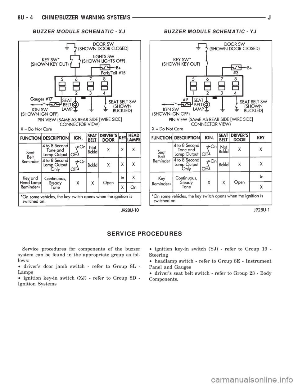
BUZZER MODULE SCHEMATIC - XJBUZZER MODULE SCHEMATIC - YJ
8U - 4 CHIME/BUZZER WARNING SYSTEMSJ
Page 538 of 2158
the following procedures to reduce the possibility of
electrostatic charge build up on the body and inad-
vertent discharge into the component. If it is not
known whether the part is ESD sensitive, assume
that it is.
(1) Always touch a known good ground before han-
dling the part. This should be repeated while han-
dling the part and more frequently after sliding
across a seat, sitting down from a standing position,
or walking a distance.
(2) Avoid touching electrical terminals of the part,
unless instructed to do so by a written diagnostic
procedure.
(3) When using a voltmeter, be sure to connect the
ground lead first.
(4) Do not remove the part from its protective pack-
ing until it is time to install the part.
(5) Before removing the part from its package,
ground the package to a known good ground on the
vehicle.
TROUBLESHOOTING TOOLS
When diagnosing a problem in an electrical circuit
there are several common tools necessary. These tools
are listed and explained below.
²Jumper Wire - This is a test wire used to connect
two points of a circuit. It can be used to bypass an
open in a circuit.
WARNING: NEVER USE A JUMPER WIRE ACROSS A
LOAD, SUCH AS A MOTOR, CONNECTED BETWEEN
A BATTERY FEED AND GROUND.
²Voltmeter - Used to check for voltage on a circuit.
Always connect the black lead to a known good
ground and the red lead to the positive side of the
circuit.
CAUTION: Most of the electrical components used
in today's vehicle are solid state. When checking
voltages in these circuits use a meter with a 10-
megohm or greater impedance.
²Ohmmeter - Used to check the resistance between
two points of a circuit. Low or no resistance in a
circuit means good continuity.CAUTION: - Most of the electrical components used
in today's vehicle are Solid State. When checking
resistance in these circuits use a meter with a 10-
megohm or greater impedance. In addition, make
sure the power is disconnected from the circuit.
Circuits that are powered up by the vehicle electrical
system can cause damage to the equipment and
provide false readings.
²Probing Tools - These tools are used for probing
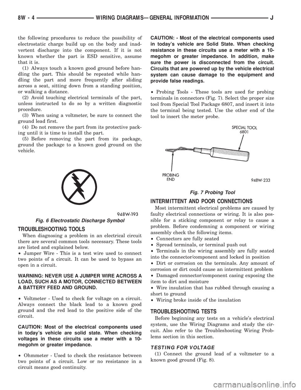
terminals in connectors (Fig. 7). Select the proper size
tool from Special Tool Package 6807, and insert it into
the terminal being tested. Use the other end of the
tool to insert the meter probe.
INTERMITTENT AND POOR CONNECTIONS
Most intermittent electrical problems are caused by
faulty electrical connections or wiring. It is also pos-
sible for a sticking component or relay to cause a
problem. Before condemning a component or wiring
assembly check the following items.
²Connectors are fully seated
²Spread terminals, or terminal push out
²Terminals in the wiring assembly are fully seated
into the connector/component and locked in position
²Dirt or corrosion on the terminals. Any amount of
corrosion or dirt could cause an intermittent problem
²Damaged connector/component casing exposing the
item to dirt and moisture
²Wire insulation that has rubbed through causing a
short to ground
²Wiring broke inside of the insulation
TROUBLESHOOTING TESTS
Before beginning any tests on a vehicle's electrical
system, use the Wiring Diagrams and study the cir-
cuit. Also refer to the Troubleshooting Wiring Prob-
lems section in this section.
TESTING FOR VOLTAGE
(1) Connect the ground lead of a voltmeter to a
known good ground (Fig. 8).
Fig. 6 Electrostatic Discharge Symbol
Fig. 7 Probing Tool
8W - 4 WIRING DIAGRAMSÐGENERAL INFORMATIONJ
Page 1285 of 2158
CYLINDER COMBUSTION PRESSURE LEAKAGE
TEST
The combustion pressure leakage test provides an
accurate means for determining engine condition.
Combustion pressure leakage testing will detect:
²Exhaust and intake valve leaks (improper seat-
ing).
²Leaks between adjacent cylinders or into water
jacket.
²Any causes for combustion/compression pressure
loss.
WARNING: DO NOT REMOVE THE RADIATOR CAP
WITH THE SYSTEM HOT AND UNDER PRESSURE
BECAUSE SERIOUS BURNS FROM COOLANT CAN
OCCUR.
Check the coolant level and fill as required. DO
NOT install the radiator cap.
Start and operate the engine until it attains nor-
mal operating temperature, then turn the engine
OFF.
Remove the spark plugs.
Remove the oil filler cap.
Remove the air cleaner.
Calibrate the tester according to the manufactur-
er's instructions. The shop air source for testing
should maintain 483 kPa (70 psi) minimum, 1 379
kPa (200 psi) maximum and 552 kPa (80 psi) recom-
mended.
Perform the test procedures on each cylinder ac-
cording to the tester manufacturer's instructions.
While testing, listen for pressurized air escaping
through the throttle body, tailpipe and oil filler cap
opening. Check for bubbles in the radiator coolant.
All gauge pressure indications should be equal,
with no more than 25% leakage.
FOR EXAMPLE:At 552 kPa (80 psi) input pres-
sure, a minimum of 414 kPa (60 psi) should be main-
tained in the cylinder.
Refer to the Cylinder Combustion Pressure Leak-
age Test Diagnosis chart.
INSPECTION (ENGINE OIL LEAKS IN GENERAL)
Begin with a through visual inspection of the en-
gine, particularly at the area of the suspected leak. If
an oil leak source is not readily identifiable, the fol-
lowing steps should be followed:
(1) Do not clean or degrease the engine at this
time because some solvents may cause rubber to
swell, temporarily stopping the leak.
(2) Add an oil soluble dye (use as recommended by
manufacturer). Start the engine and let idle for ap-
proximately 15 minutes. Check the oil dipstick to
make sure the dye is thoroughly mixed as indicated
with a bright yellow color under a black light.(3) Using a black light, inspect the entire engine
for fluorescent dye, particularly at the suspected area
of oil leak. If the oil leak is found and identified, re-
pair per service manual instructions.
(4) If dye is not observed, drive the vehicle at var-
ious speeds for approximately 24km (15 miles), and
repeat step (3).
If the oil leak source is not positively identi-
fied at this time, proceed with the air leak detec-
tion test method as follows:
(1) Disconnect the breather cap to air cleaner hose
at the breather cap end. Cap or plug breather cap
nipple.
(2) Remove the PCV valve from the cylinder head
cover. Cap or plug the PCV valve grommet.
(3) Attach an air hose with pressure gauge and
regulator to the dipstick tube.
CAUTION: Do not subject the engine assembly to
more than 20.6 kpa (3 PSI) of test pressure.
(4) Gradually apply air pressure from 1 psi to 2.5
psi maximum while applying soapy water at the sus-
pected source. Adjust the regulator to the suitable
test pressure that provide the best bubbles which
will pinpoint the leak source. If the oil leak is de-
tected and identified, repair per service manual pro-
cedures.
(5) If the leakage occurs at the rear oil seal area,
refer to the section, Inspection for Rear Seal Area
Leak.
(6) If no leaks are detected, turn off the air supply
and remove the air hose and all plugs and caps. In-
stall the PCV valve and breather cap hose. Proceed
to step 7.
(7) Clean the oil off the suspect oil leak area using
a suitable solvent. Drive the vehicle at various
speeds approximately 24 km (15 miles). Inspect the
engine for signs of an oil leak by using a black light.
INSPECTION FOR REAR SEAL AREA LEAKS
Since it is sometimes difficult to determine the
source of an oil leak in the rear seal area of the en-
gine, a more involved inspection is necessary. The fol-
lowing steps should be followed to help pinpoint the
source of the leak.
If the leakage occurs at the crankshaft rear oil seal
area:
(1) Disconnect the battery.
(2) Raise the vehicle.
(3) Remove torque converter or clutch housing
cover and inspect rear of block for evidence of oil.
Use a black light to check for the oil leak:
(a) Circular spray pattern generally indicates
seal leakage or crankshaft damage.
(b) Where leakage tends to run straight down,
possible causes are a porous block, distributor seal,
camshaft bore cup plugs oil galley pipe plugs, oil
9 - 6 ENGINESJ