1995 JEEP YJ body procedures
[x] Cancel search: body proceduresPage 1466 of 2158
(2) Place a small container or shop towel beneath
the switch to collect any excess fluid.
(3) Remove the switch.
INSTALLATION
(1) Install the power steering switch.
(2) Connect the electrical connector to the switch.
(3) Check power steering fluid and add as neces-
sary.
(4) Start the engine and again check power steer-
ing fluid. Add fluid if necessary.
POWERTRAIN CONTROL MODULE (PCM)
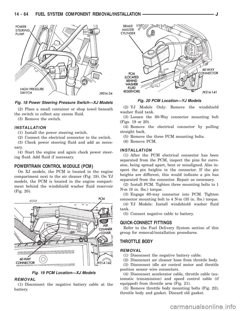
On XJ models, the PCM is located in the engine
compartment next to the air cleaner (Fig. 19). On YJ
models, the PCM is located in the engine compart-
ment behind the windshield washer fluid reservoir
(Fig. 20).
REMOVAL
(1) Disconnect the negative battery cable at the
battery.(2) YJ Models Only: Remove the windshield
washer fluid tank.
(3) Loosen the 60-Way connector mounting bolt
(Figs. 19 or 20).
(4) Remove the electrical connector by pulling
straight back.
(5) Remove the three PCM mounting bolts.
(6) Remove PCM.
INSTALLATION
(1) After the PCM electrical connector has been
separated from the PCM, inspect the pins for corro-
sion, being spread apart, bent or misaligned. Also in-
spect the pin heights in the connector. If the pin
heights are different, this would indicate a pin has
separated from the connector. Repair as necessary.
(2) Install PCM. Tighten three mounting bolts to 1
Nzm (9 in. lbs.) torque.
(3) Engage 60-way connector into PCM. Tighten
connector mounting bolt to 4 Nzm (35 in. lbs.) torque.
(4) YJ Models: Install windshield washer fluid
tank.
(5) Connect negative cable to battery.
QUICK-CONNECT FITTINGS
Refer to the Fuel Delivery System section of this
group for removal/installation procedures.
THROTTLE BODY
REMOVAL
(1) Disconnect the negative battery cable.
(2) Disconnect air cleaner hose from throttle body.
(3) Disconnect idle air control motor and throttle
position sensor wire connectors.
(4) Disconnect accelerator cable, throttle cable (au-
tomatic transmission) and speed control cable (if
equipped) from throttle arm (Fig. 21).
(5) Remove throttle body mounting bolts (Fig. 22),
throttle body and gasket. Discard old gasket.
Fig. 18 Power Steering Pressure SwitchÐXJ Models
Fig. 19 PCM LocationÐXJ Models
Fig. 20 PCM LocationÐYJ Models
14 - 64 FUEL SYSTEM COMPONENT REMOVAL/INSTALLATIONJ
Page 1661 of 2158
30RH/32RH IN-VEHICLE SERVICE
INDEX
page page
Converter Drainback Check Valve Service...... 113
Fluid and Filter Replacement................. 99
Fluid Level Check......................... 99
Front Band Adjustment.................... 102
Governor and Park Gear Service............. 105
Oil Filter Replacement..................... 103
Park Interlock Cable Adjustment (XJ).......... 101
Park Lock Component Replacement.......... 108
Park/Neutral Position Switch Service.......... 109
Rear Band Adjustment.................... 103
Recommended Fluid....................... 99Refilling After Overhaul or Fluid/Filter Change . . . 100
Shift Cable Adjustment (XJ)................. 100
Shift Linkage Adjustment (YJ)............... 100
Speedometer Service..................... 109
Throttle Valve Cable Adjustment (XJ/YJ)....... 101
Transmission Cooler Flow Testing............ 113
Transmission Cooler Line and Fitting Service.... 111
Transmission Cooler Reverse Flushing......... 114
Valve Body Installation.................... 104
Valve Body Removal...................... 104
Valve Body Service....................... 104
RECOMMENDED FLUID
Recommended (and preferred) fluid for 30RH/32RH
transmissions is Mopar ATF Plus, type 7176.
Dexron II is not really recommended and should
only be used when ATF Plus is not available.
FLUID LEVEL CHECK
Transmission fluid level should be checked monthly
under normal operation. If the vehicle is used for
trailer towing or similar heavy load hauling, check
fluid level and condition weekly.
Fluid level is checked with the engine running at
curb idle speed, the transmission in Neutral and the
transmission fluid at normal operating temperature.
FLUID LEVEL CHECK PROCEDURE
(1) Transmission fluid must be at normal operating
temperature for accurate fluid level check. Drive ve-
hicle if necessary to bring fluid temperature up to
normal hot operating temperature of 82ÉC (180ÉF).
(2) Position vehicle on level surface. This is ex-
tremely important for accurate fluid level check.
(3) Start and run engine at curb idle speed.
(4) Apply parking brakes.
(5) Shift transmission momentarily into all gear
ranges. Then shift transmission back to Neutral.
(6) Clean top of filler tube and dipstick to keep dirt
from entering tube.
(7) Remove dipstick and check fluid level as fol-
lows:
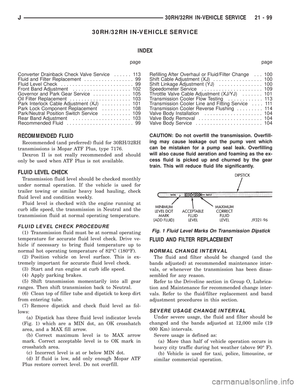
(a) Dipstick has three fluid level indicator levels
(Fig. 1) which are a MIN dot, an OK crosshatch
area, and a MAX fill arrow.
(b) Correct maximum level is to MAX arrow
mark. Correct acceptable level is to OK mark in
crosshatch area.
(c) Incorrect level is at or below MIN dot.
(d) If fluid is low, add only enough Mopar ATF
Plus restore correct level. Do not overfill.CAUTION: Do not overfill the transmission. Overfill-
ing may cause leakage out the pump vent which
can be mistaken for a pump seal leak. Overfilling
will also cause fluid aeration and foaming as the ex-
cess fluid is picked up and churned by the gear
train. This will reduce fluid life significantly.
FLUID AND FILTER REPLACEMENT
NORMAL CHANGE INTERVAL
The fluid and filter should be changed (and the
bands adjusted) at recommended maintenance inter-
vals, or whenever the transmission has been disas-
sembled for any reason.
Refer to the Driveline section in Group O, Lubrica-
tion and Maintenance for recommended change inter-
vals. Refer to the fluid/filter replacement and band
adjustment procedures in this section.
SEVERE USAGE CHANGE INTERVAL
Under severe usage, the fluid and filter should be
changed and the bands adjusted at 12,000 mile (19
000 Km) intervals.
Severe usage is defined as:
(a) More than half of vehicle operation occurs in
heavy city traffic during hot weather (above 90É F).
(b) Vehicle is used for taxi, police, limousine, or
similar commercial operation.
Fig. 1 Fluid Level Marks On Transmission Dipstick
J30RH/32RH IN-VEHICLE SERVICE 21 - 99
Page 1666 of 2158
on transmission. Tighten pan bolts to 17 Nzm (150 in.
lbs.) torque.
(7) Lower vehicle.
(8) Refill transmission with Mopar ATF Plus.
VALVE BODY REMOVAL
(1) Raise vehicle.
(2) Remove oil pan and drain fluid.
(3) Disconnect gearshift and throttle linkage at
transmission levers.
(4) Loosen clamp bolts and remove throttle and
manual valve levers from manual valve shaft.
(5) Disconnect park/neutral position switch wires
and remove switch and switch seal.
(6) Remove valve body oil filter.
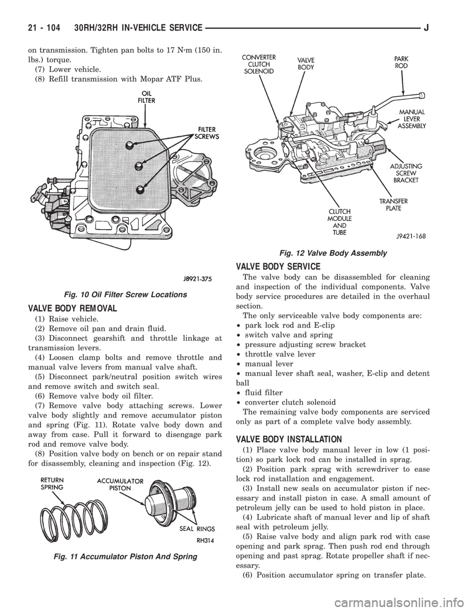
(7) Remove valve body attaching screws. Lower
valve body slightly and remove accumulator piston
and spring (Fig. 11). Rotate valve body down and
away from case. Pull it forward to disengage park
rod and remove valve body.
(8) Position valve body on bench or on repair stand
for disassembly, cleaning and inspection (Fig. 12).
VALVE BODY SERVICE
The valve body can be disassembled for cleaning
and inspection of the individual components. Valve
body service procedures are detailed in the overhaul
section.
The only serviceable valve body components are:
²park lock rod and E-clip
²switch valve and spring
²pressure adjusting screw bracket
²throttle valve lever
²manual lever
²manual lever shaft seal, washer, E-clip and detent
ball
²fluid filter
²converter clutch solenoid
The remaining valve body components are serviced
only as part of a complete valve body assembly.
VALVE BODY INSTALLATION
(1) Place valve body manual lever in low (1 posi-
tion) so park lock rod can be installed in sprag.
(2) Position park sprag with screwdriver to ease
lock rod installation and engagement.
(3) Install new seals on accumulator piston if nec-
essary and install piston in case. A small amount of
petroleum jelly can be used to hold piston in place.
(4) Lubricate shaft of manual lever and lip of shaft
seal with petroleum jelly.
(5) Raise valve body and align park rod with case
opening and park sprag. Then push rod end through
opening and past sprag. Rotate propeller shaft if nec-
essary.
(6) Position accumulator spring on transfer plate.
Fig. 10 Oil Filter Screw Locations
Fig. 11 Accumulator Piston And Spring
Fig. 12 Valve Body Assembly
21 - 104 30RH/32RH IN-VEHICLE SERVICEJ
Page 1672 of 2158
speed sensor and metal adapter (Fig. 25). Service
procedures for both styles are described in the follow-
ing procedures.
SPEEDOMETER ASSEMBLY REMOVAL (WITH
UNIT STYLE SENSOR)
(1) Raise vehicle.
(2) Disconnect wires from vehicle speed sensor.
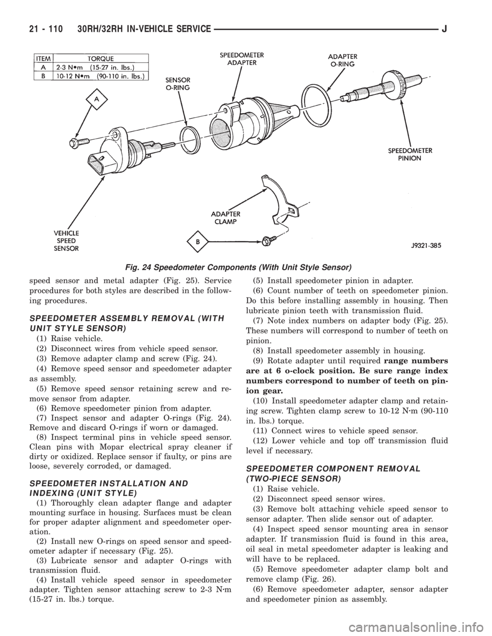
(3) Remove adapter clamp and screw (Fig. 24).
(4) Remove speed sensor and speedometer adapter
as assembly.
(5) Remove speed sensor retaining screw and re-
move sensor from adapter.
(6) Remove speedometer pinion from adapter.
(7) Inspect sensor and adapter O-rings (Fig. 24).
Remove and discard O-rings if worn or damaged.
(8) Inspect terminal pins in vehicle speed sensor.
Clean pins with Mopar electrical spray cleaner if
dirty or oxidized. Replace sensor if faulty, or pins are
loose, severely corroded, or damaged.
SPEEDOMETER INSTALLATION AND
INDEXING (UNIT STYLE)
(1) Thoroughly clean adapter flange and adapter
mounting surface in housing. Surfaces must be clean
for proper adapter alignment and speedometer oper-
ation.
(2) Install new O-rings on speed sensor and speed-
ometer adapter if necessary (Fig. 25).
(3) Lubricate sensor and adapter O-rings with
transmission fluid.
(4) Install vehicle speed sensor in speedometer
adapter. Tighten sensor attaching screw to 2-3 Nzm
(15-27 in. lbs.) torque.(5) Install speedometer pinion in adapter.
(6) Count number of teeth on speedometer pinion.
Do this before installing assembly in housing. Then
lubricate pinion teeth with transmission fluid.
(7) Note index numbers on adapter body (Fig. 25).
These numbers will correspond to number of teeth on
pinion.
(8) Install speedometer assembly in housing.
(9) Rotate adapter until requiredrange numbers
are at 6 o-clock position. Be sure range index
numbers correspond to number of teeth on pin-
ion gear.
(10) Install speedometer adapter clamp and retain-
ing screw. Tighten clamp screw to 10-12 Nzm (90-110
in. lbs.) torque.
(11) Connect wires to vehicle speed sensor.
(12) Lower vehicle and top off transmission fluid
level if necessary.
SPEEDOMETER COMPONENT REMOVAL
(TWO-PIECE SENSOR)
(1) Raise vehicle.
(2) Disconnect speed sensor wires.
(3) Remove bolt attaching vehicle speed sensor to
sensor adapter. Then slide sensor out of adapter.
(4) Inspect speed sensor mounting area in sensor
adapter. If transmission fluid is found in this area,
oil seal in metal speedometer adapter is leaking and
will have to be replaced.
(5) Remove speedometer adapter clamp bolt and
remove clamp (Fig. 26).
(6) Remove speedometer adapter, sensor adapter
and speedometer pinion as assembly.
Fig. 24 Speedometer Components (With Unit Style Sensor)
21 - 110 30RH/32RH IN-VEHICLE SERVICEJ
Page 1681 of 2158
30RH/32RH TRANSMISSION OVERHAUL
INDEX
page page
Adapter/Extension Housing Inspection and Park
Lock Component Overhaul................ 127
Front Clutch Overhaul..................... 134
Front Servo and Band Overhaul............. 146
Governor and Park Gear Overhaul........... 127
Oil Pump Overhaul....................... 131
Overhaul Service Information................ 125
Overrunning ClutchÐLow-Reverse DrumÐRear
Support Overhaul....................... 125
Planetary Gear Train Overhaul.............. 141Rear Clutch Overhaul..................... 138
Rear Servo and Band Overhaul.............. 146
Transmission Assembly and Adjustment Procedures. 155
Transmission Assembly Tips................ 155
Transmission Case Cleaning and Inspection.... 125
Transmission Disassembly.................. 119
Valve Body Assembly and Adjustment......... 153
Valve Body Disassembly and Inspection....... 147
TRANSMISSION DISASSEMBLY
(1) Clean transmission exterior with steam gun or
with solvent. Wear eye protection during cleaning
process.
(2) Remove throttle and shift levers from valve
body manual shaft and throttle lever shaft.
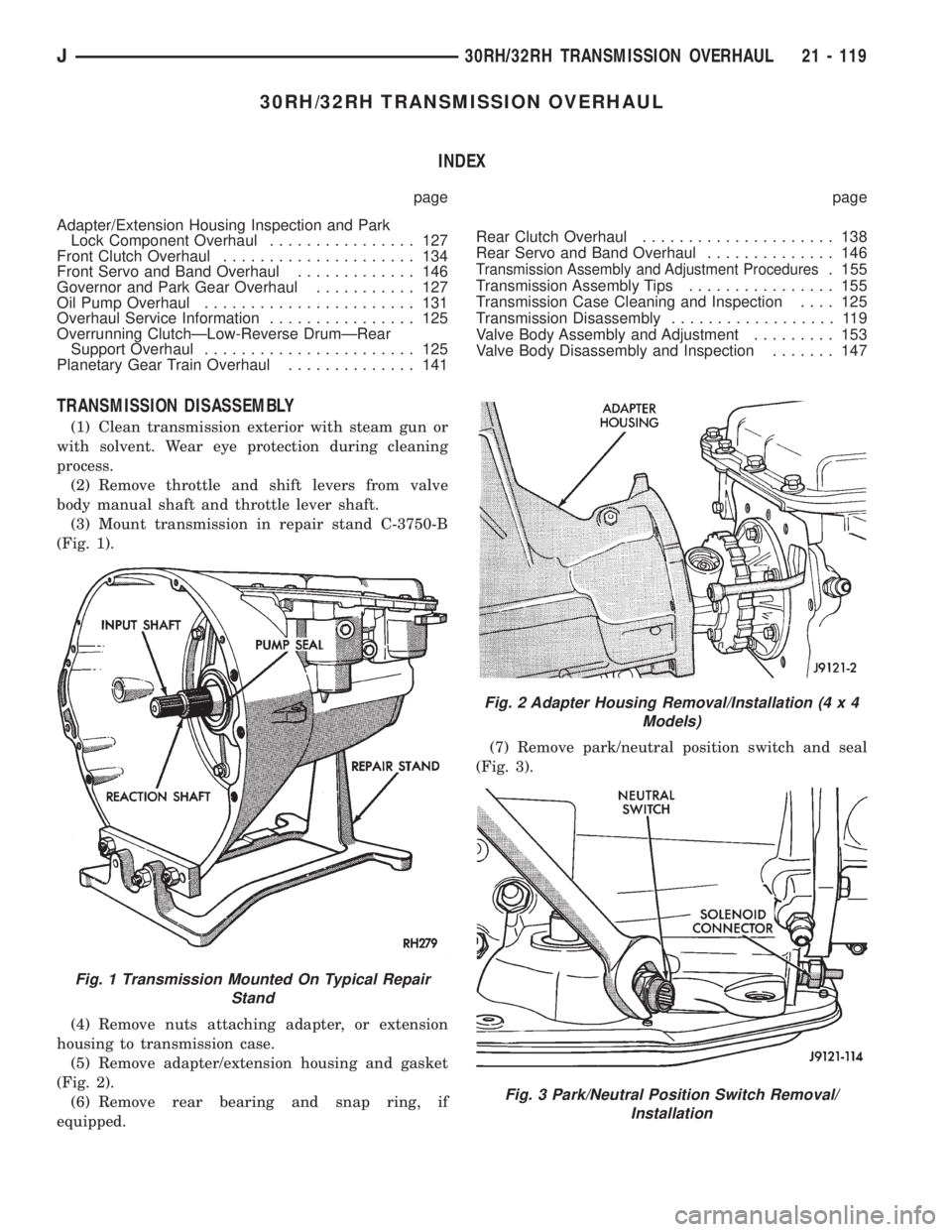
(3) Mount transmission in repair stand C-3750-B
(Fig. 1).
(4) Remove nuts attaching adapter, or extension
housing to transmission case.
(5) Remove adapter/extension housing and gasket
(Fig. 2).
(6) Remove rear bearing and snap ring, if
equipped.(7) Remove park/neutral position switch and seal
(Fig. 3).
Fig. 1 Transmission Mounted On Typical Repair
Stand
Fig. 2 Adapter Housing Removal/Installation (4 x 4
Models)
Fig. 3 Park/Neutral Position Switch Removal/
Installation
J30RH/32RH TRANSMISSION OVERHAUL 21 - 119
Page 1717 of 2158
justment must be performed properly and in the cor-
rect sequence. The correct sequence is line pressure
adjustment first and throttle pressure adjustment
last.
Line Pressure Adjustment
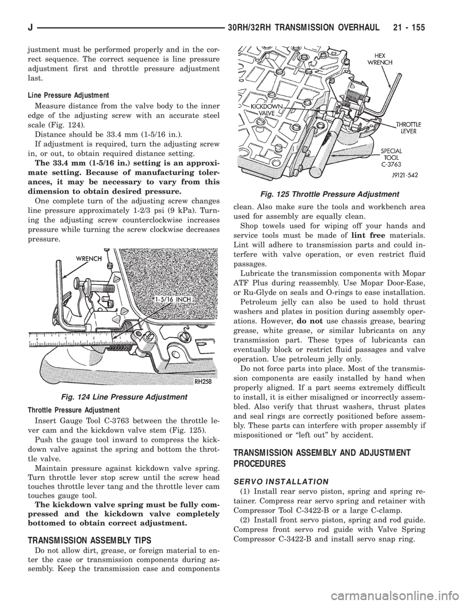
Measure distance from the valve body to the inner
edge of the adjusting screw with an accurate steel
scale (Fig. 124).
Distance should be 33.4 mm (1-5/16 in.).
If adjustment is required, turn the adjusting screw
in, or out, to obtain required distance setting.
The 33.4 mm (1-5/16 in.) setting is an approxi-
mate setting. Because of manufacturing toler-
ances, it may be necessary to vary from this
dimension to obtain desired pressure.
One complete turn of the adjusting screw changes
line pressure approximately 1-2/3 psi (9 kPa). Turn-
ing the adjusting screw counterclockwise increases
pressure while turning the screw clockwise decreases
pressure.
Throttle Pressure Adjustment
Insert Gauge Tool C-3763 between the throttle le-
ver cam and the kickdown valve stem (Fig. 125).
Push the gauge tool inward to compress the kick-
down valve against the spring and bottom the throt-
tle valve.
Maintain pressure against kickdown valve spring.
Turn throttle lever stop screw until the screw head
touches throttle lever tang and the throttle lever cam
touches gauge tool.
The kickdown valve spring must be fully com-
pressed and the kickdown valve completely
bottomed to obtain correct adjustment.
TRANSMISSION ASSEMBLY TIPS
Do not allow dirt, grease, or foreign material to en-
ter the case or transmission components during as-
sembly. Keep the transmission case and componentsclean. Also make sure the tools and workbench area
used for assembly are equally clean.
Shop towels used for wiping off your hands and
service tools must be made oflint freematerials.
Lint will adhere to transmission parts and could in-
terfere with valve operation, or even restrict fluid
passages.
Lubricate the transmission components with Mopar
ATF Plus during reassembly. Use Mopar Door-Ease,
or Ru-Glyde on seals and O-rings to ease installation.
Petroleum jelly can also be used to hold thrust
washers and plates in position during assembly oper-
ations. However,do notuse chassis grease, bearing
grease, white grease, or similar lubricants on any
transmission part. These types of lubricants can
eventually block or restrict fluid passages and valve
operation. Use petroleum jelly only.
Do not force parts into place. Most of the transmis-
sion components are easily installed by hand when
properly aligned. If a part seems extremely difficult
to install, it is either misaligned or incorrectly assem-
bled. Also verify that thrust washers, thrust plates
and seal rings are correctly positioned before assem-
bly. These parts can interfere with proper assembly if
mispositioned or ``left out'' by accident.
TRANSMISSION ASSEMBLY AND ADJUSTMENT
PROCEDURES
SERVO INSTALLATION
(1) Install rear servo piston, spring and spring re-
tainer. Compress rear servo spring and retainer with
Compressor Tool C-3422-B or a large C-clamp.
(2) Install front servo piston, spring and rod guide.
Compress front servo rod guide with Valve Spring
Compressor C-3422-B and install servo snap ring.
Fig. 124 Line Pressure Adjustment
Fig. 125 Throttle Pressure Adjustment
J30RH/32RH TRANSMISSION OVERHAUL 21 - 155
Page 1748 of 2158
(6) Lubricate new O-ring and install it on adapter.
(7) Install solenoid wire harness and adapter in
case.
(8) Install adapter bracket and bracket bolt.
(9) Connect wires to solenoids.
(10) Install oil screen and oil pan.
TRANSMISSION VALVE BODY REMOVAL
Removal and installation are the only valve body
service procedures covered in this section. Refer to
the transmission overhaul section for valve body dis-
assembly, cleaning, inspection and reassembly.
(1) Remove oil pan plug and drain transmission
fluid.
(2) Remove oil pan and oil screen. Clean pan and
screen in solvent and dry them with compressed air.
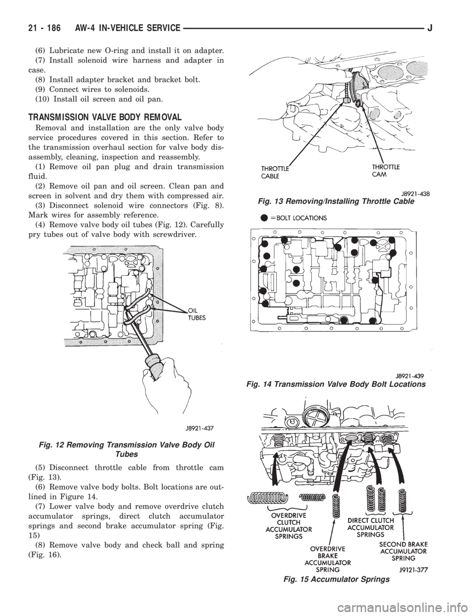
(3) Disconnect solenoid wire connectors (Fig. 8).
Mark wires for assembly reference.
(4) Remove valve body oil tubes (Fig. 12). Carefully
pry tubes out of valve body with screwdriver.
(5) Disconnect throttle cable from throttle cam
(Fig. 13).
(6) Remove valve body bolts. Bolt locations are out-
lined in Figure 14.
(7) Lower valve body and remove overdrive clutch
accumulator springs, direct clutch accumulator
springs and second brake accumulator spring (Fig.
15)
(8) Remove valve body and check ball and spring
(Fig. 16).
Fig. 13 Removing/Installing Throttle Cable
Fig. 14 Transmission Valve Body Bolt Locations
Fig. 15 Accumulator Springs
Fig. 12 Removing Transmission Valve Body Oil
Tubes
21 - 186 AW-4 IN-VEHICLE SERVICEJ
Page 1814 of 2158
REMOVING UPPER BODY FROM LOWER BODY
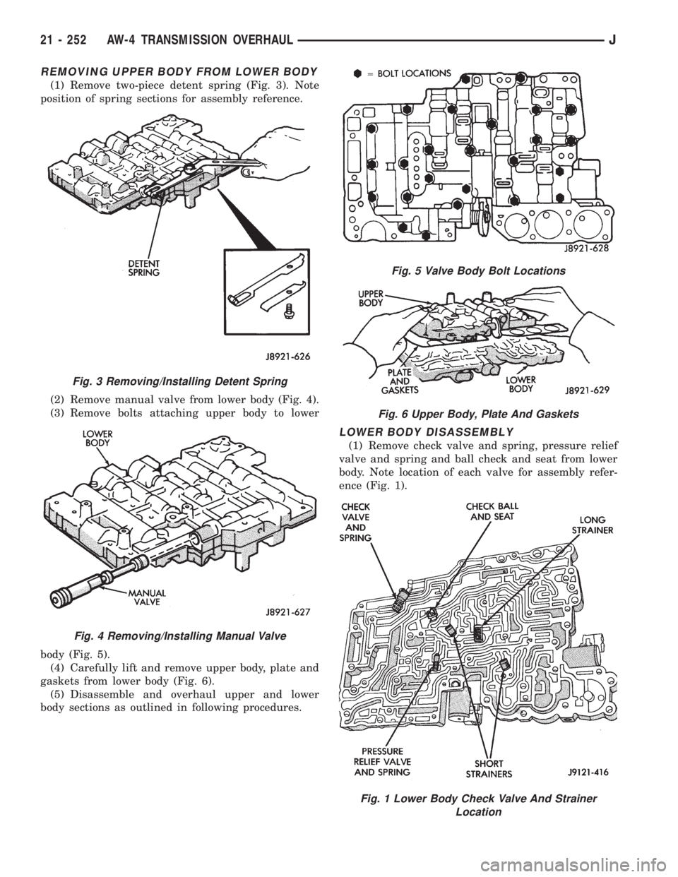
(1) Remove two-piece detent spring (Fig. 3). Note
position of spring sections for assembly reference.
(2) Remove manual valve from lower body (Fig. 4).
(3) Remove bolts attaching upper body to lower
body (Fig. 5).
(4) Carefully lift and remove upper body, plate and
gaskets from lower body (Fig. 6).
(5) Disassemble and overhaul upper and lower
body sections as outlined in following procedures.
LOWER BODY DISASSEMBLY
(1) Remove check valve and spring, pressure relief
valve and spring and ball check and seat from lower
body. Note location of each valve for assembly refer-
ence (Fig. 1).
Fig. 3 Removing/Installing Detent Spring
Fig. 4 Removing/Installing Manual Valve
Fig. 5 Valve Body Bolt Locations
Fig. 6 Upper Body, Plate And Gaskets
Fig. 1 Lower Body Check Valve And Strainer
Location
21 - 252 AW-4 TRANSMISSION OVERHAULJ