1995 JEEP YJ torque
[x] Cancel search: torquePage 1507 of 2158
PITMAN SHAFT SEALSÐIN CAR REPLACEMENT
REMOVAL
(1) Remove pitman arm from gear. Refer to Pitman
Arm Removal in Steering Linkage.
(2) Clean exposed end of pitman shaft and hous-
ing. Use a wire brush to clean the shaft splines.
(3) Remove retaining ring with snap ring pliers
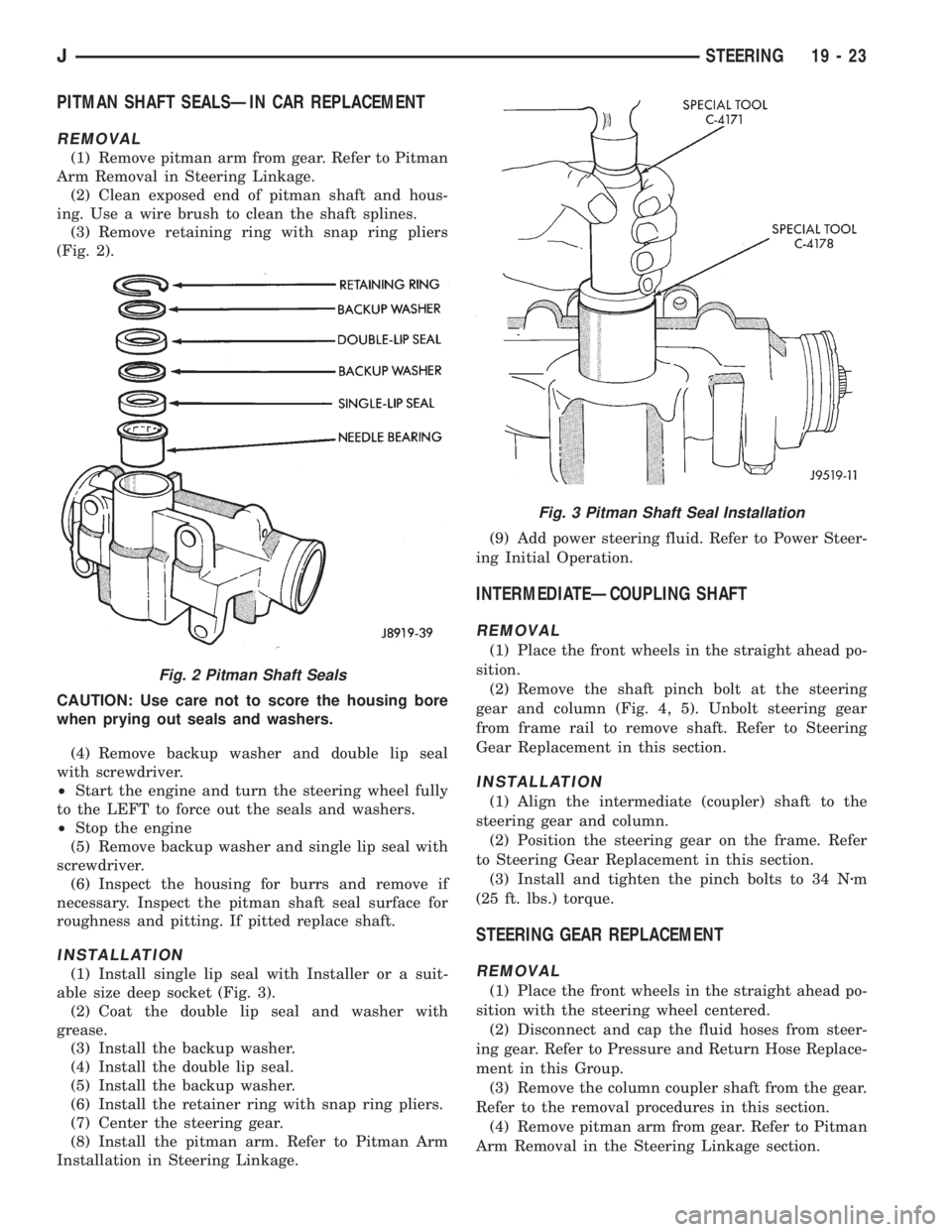
(Fig. 2).
CAUTION: Use care not to score the housing bore
when prying out seals and washers.
(4) Remove backup washer and double lip seal
with screwdriver.
²Start the engine and turn the steering wheel fully
to the LEFT to force out the seals and washers.
²Stop the engine
(5) Remove backup washer and single lip seal with
screwdriver.
(6) Inspect the housing for burrs and remove if
necessary. Inspect the pitman shaft seal surface for
roughness and pitting. If pitted replace shaft.
INSTALLATION
(1) Install single lip seal with Installer or a suit-
able size deep socket (Fig. 3).
(2) Coat the double lip seal and washer with
grease.
(3) Install the backup washer.
(4) Install the double lip seal.
(5) Install the backup washer.
(6) Install the retainer ring with snap ring pliers.
(7) Center the steering gear.
(8) Install the pitman arm. Refer to Pitman Arm
Installation in Steering Linkage.(9) Add power steering fluid. Refer to Power Steer-
ing Initial Operation.
INTERMEDIATEÐCOUPLING SHAFT
REMOVAL
(1) Place the front wheels in the straight ahead po-
sition.
(2) Remove the shaft pinch bolt at the steering
gear and column (Fig. 4, 5). Unbolt steering gear
from frame rail to remove shaft. Refer to Steering
Gear Replacement in this section.
INSTALLATION
(1) Align the intermediate (coupler) shaft to the
steering gear and column.
(2) Position the steering gear on the frame. Refer
to Steering Gear Replacement in this section.
(3) Install and tighten the pinch bolts to 34 Nzm
(25 ft. lbs.) torque.
STEERING GEAR REPLACEMENT
REMOVAL
(1) Place the front wheels in the straight ahead po-
sition with the steering wheel centered.
(2) Disconnect and cap the fluid hoses from steer-
ing gear. Refer to Pressure and Return Hose Replace-
ment in this Group.
(3) Remove the column coupler shaft from the gear.
Refer to the removal procedures in this section.
(4) Remove pitman arm from gear. Refer to Pitman
Arm Removal in the Steering Linkage section.
Fig. 2 Pitman Shaft Seals
Fig. 3 Pitman Shaft Seal Installation
JSTEERING 19 - 23
Page 1508 of 2158
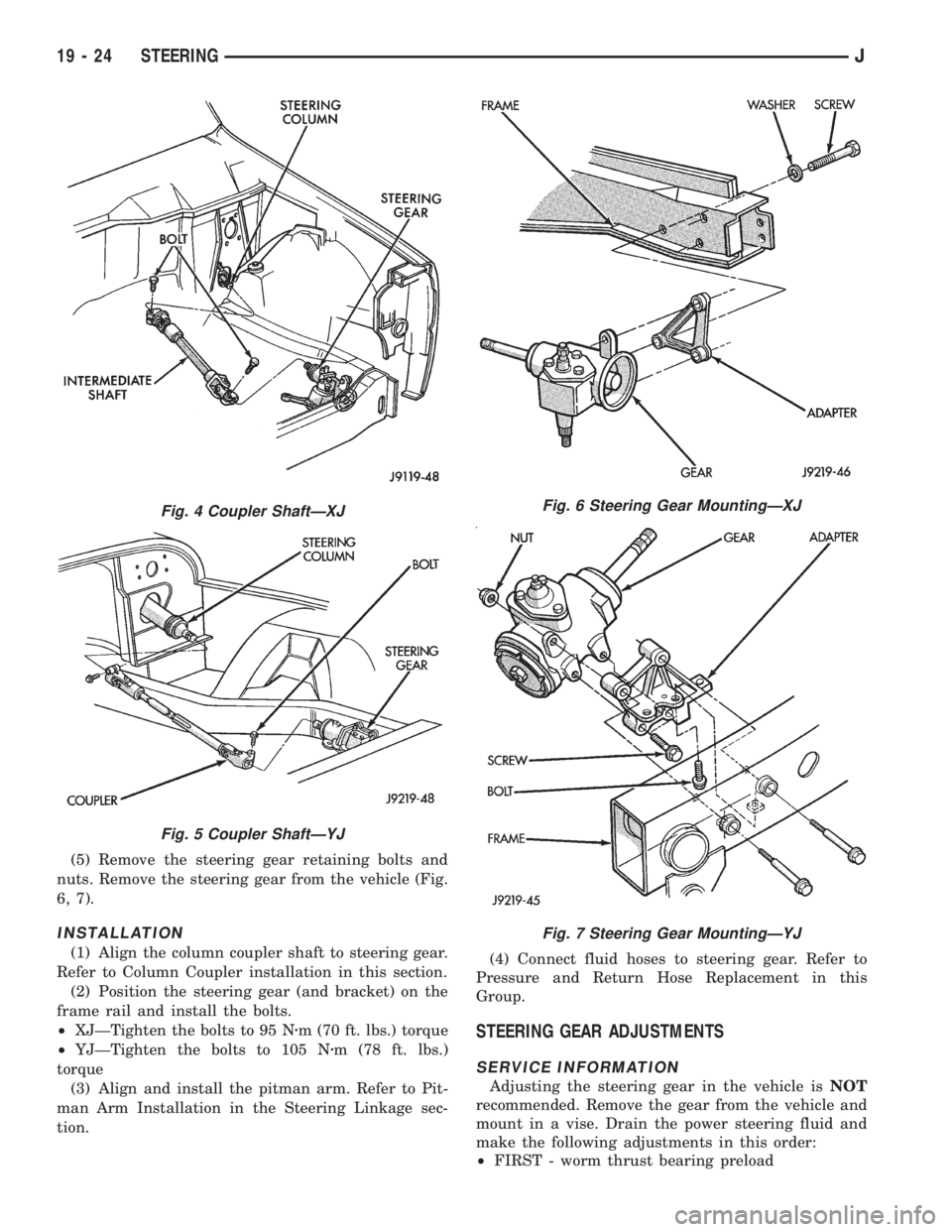
(5) Remove the steering gear retaining bolts and
nuts. Remove the steering gear from the vehicle (Fig.
6, 7).
INSTALLATION
(1) Align the column coupler shaft to steering gear.
Refer to Column Coupler installation in this section.
(2) Position the steering gear (and bracket) on the
frame rail and install the bolts.
²XJÐTighten the bolts to 95 Nzm (70 ft. lbs.) torque
²YJÐTighten the bolts to 105 Nzm (78 ft. lbs.)
torque
(3) Align and install the pitman arm. Refer to Pit-
man Arm Installation in the Steering Linkage sec-
tion.(4) Connect fluid hoses to steering gear. Refer to
Pressure and Return Hose Replacement in this
Group.
STEERING GEAR ADJUSTMENTS
SERVICE INFORMATION
Adjusting the steering gear in the vehicle isNOT
recommended. Remove the gear from the vehicle and
mount in a vise. Drain the power steering fluid and
make the following adjustments in this order:
²FIRST - worm thrust bearing preload
Fig. 4 Coupler ShaftÐXJ
Fig. 5 Coupler ShaftÐYJ
Fig. 6 Steering Gear MountingÐXJ
Fig. 7 Steering Gear MountingÐYJ
19 - 24 STEERINGJ
Page 1509 of 2158
²SECOND - over-center preload adjustment
WORM THRUST BEARING PRELOAD
ADJUSTMENT
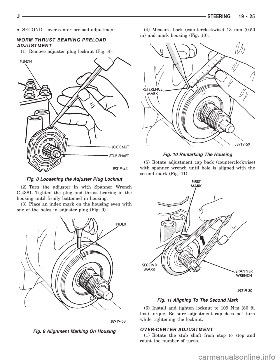
(1) Remove adjuster plug locknut (Fig. 8).
(2) Turn the adjuster in with Spanner Wrench
C-4381. Tighten the plug and thrust bearing in the
housing until firmly bottomed in housing.
(3) Place an index mark on the housing even with
one of the holes in adjuster plug (Fig. 9).(4) Measure back (counterclockwise) 13 mm (0.50
in) and mark housing (Fig. 10).
(5) Rotate adjustment cap back (counterclockwise)
with spanner wrench until hole is aligned with the
second mark (Fig. 11).
(6) Install and tighten locknut to 109 Nzm (80 ft.
lbs.) torque. Be sure adjustment cap does not turn
while tightening the locknut.
OVER-CENTER ADJUSTMENT
(1) Rotate the stub shaft from stop to stop and
count the number of turns.
Fig. 10 Remarking The Housing
Fig. 11 Aligning To The Second Mark
Fig. 8 Loosening the Adjuster Plug Locknut
Fig. 9 Alignment Marking On Housing
JSTEERING 19 - 25
Page 1510 of 2158
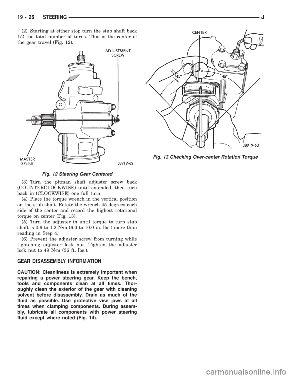
(2) Starting at either stop turn the stub shaft back
1/2 the total number of turns. This is the center of
the gear travel (Fig. 12).
(3) Turn the pitman shaft adjuster screw back
(COUNTERCLOCKWISE) until extended, then turn
back in (CLOCKWISE) one full turn.
(4) Place the torque wrench in the vertical position
on the stub shaft. Rotate the wrench 45 degrees each
side of the center and record the highest rotational
torque on center (Fig. 13).
(5) Turn the adjuster in until torque to turn stub
shaft is 0.6 to 1.2 Nzm (6.0 to 10.0 in. lbs.) more than
reading in Step 4.
(6) Prevent the adjuster screw from turning while
tightening adjuster lock nut. Tighten the adjuster
lock nut to 49 Nzm (36 ft. lbs.).
GEAR DISASSEMBLY INFORMATION
CAUTION: Cleanliness is extremely important when
repairing a power steering gear. Keep the bench,
tools and components clean at all times. Thor-
oughly clean the exterior of the gear with cleaning
solvent before disassembly. Drain as much of the
fluid as possible. Use protective vise jaws at all
times when clamping components. During assem-
bly, lubricate all components with power steering
fluid except where noted (Fig. 14).
Fig. 12 Steering Gear Centered
Fig. 13 Checking Over-center Rotation Torque
19 - 26 STEERINGJ
Page 1517 of 2158
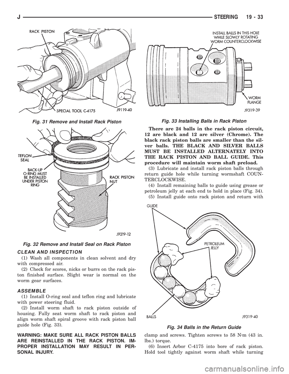
CLEAN AND INSPECTION
(1) Wash all components in clean solvent and dry
with compressed air.
(2) Check for scores, nicks or burrs on the rack pis-
ton finished surface. Slight wear is normal on the
worm gear surfaces.
ASSEMBLE
(1) Install O-ring seal and teflon ring and lubricate
with power steering fluid.
(2) Install worm shaft to rack piston outside of
housing. Fully seat worm shaft to rack piston and
align worm shaft spiral groove with rack piston ball
guide hole (Fig. 33).
WARNING: MAKE SURE ALL RACK PISTON BALLS
ARE REINSTALLED IN THE RACK PISTON. IM-
PROPER INSTALLATION MAY RESULT IN PER-
SONAL INJURY.There are 24 balls in the rack piston circuit,
12 are black and 12 are silver (Chrome). The
black rack piston balls are smaller than the sil-
ver balls. THE BLACK AND SILVER BALLS
MUST BE INSTALLED ALTERNATELY INTO
THE RACK PISTON AND BALL GUIDE. This
procedure will maintain worm shaft preload.
(3) Lubricate and install rack piston balls through
return guide hole while turning wormshaft COUN-
TERCLOCKWISE.
(4) Install remaining balls to guide using grease or
petroleum jelly at each end to hold in place (Fig. 34).
(5) Install guide onto rack piston and return with
clamp and screws. Tighten screws to 58 Nzm (43 in.
lbs.) torque.
(6) Insert Arbor C-4175 into bore of rack piston.
Hold tool tightly against worm shaft while turning
Fig. 31 Remove and Install Rack Piston
Fig. 32 Remove and Install Seal on Rack Piston
Fig. 33 Installing Balls in Rack Piston
Fig. 34 Balls in the Return Guide
JSTEERING 19 - 33
Page 1518 of 2158
the stub shaft COUNTERCLOCKWISE.
²The rack piston will be forced onto the tool and
hold the rack piston balls in place.
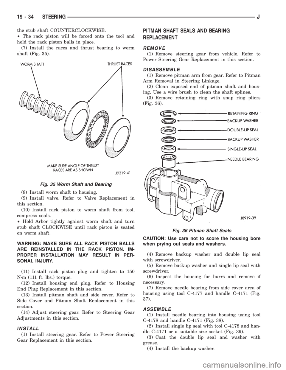
(7) Install the races and thrust bearing to worm
shaft (Fig. 35).
(8) Install worm shaft to housing.
(9) Install valve. Refer to Valve Replacement in
this section.
(10) Install rack piston to worm shaft from tool,
compress seals.
²Hold Arbor tightly against worm shaft and turn
stub shaft CLOCKWISE until rack piston is seated
on worm shaft.
WARNING: MAKE SURE ALL RACK PISTON BALLS
ARE REINSTALLED IN THE RACK PISTON. IM-
PROPER INSTALLATION MAY RESULT IN PER-
SONAL INJURY.
(11) Install rack piston plug and tighten to 150
Nzm (111 ft. lbs.) torque.
(12) Install housing end plug. Refer to Housing
End Plug Replacement in this section.
(13) Install pitman shaft and side cover. Refer to
Side Cover and Pitman Shaft Replacement in this
section.
(14) Adjust steering gear. Refer to Steering Gear
Adjustments in this section.
INSTALL
(1) Install steering gear. Refer to Power Steering
Gear Replacement in this section.
PITMAN SHAFT SEALS AND BEARING
REPLACEMENT
REMOVE
(1) Remove steering gear from vehicle. Refer to
Power Steering Gear Replacement in this section.
DISASSEMBLE
(1) Remove pitman arm from gear. Refer to Pitman
Arm Removal in Steering Linkage.
(2) Clean exposed end of pitman shaft and hous-
ing. Use a wire brush to clean the shaft splines.
(3) Remove retaining ring with snap ring pliers
(Fig. 36).
CAUTION: Use care not to score the housing bore
when prying out seals and washers.
(4) Remove backup washer and double lip seal
with screwdriver.
(5) Remove backup washer and single lip seal with
screwdriver.
(6) Inspect the housing for burrs and remove if
necessary.
(7) Remove needle bearing from side cover area of
housing using tool C-4177 and handle C-4171 (Fig.
37).
ASSEMBLE
(1) Install needle bearing into housing using tool
C-4178 and handle C-4171 (Fig. 38).
(2) Install single lip seal with tool C-4178 and han-
dle C-4171 or a suitable size socket (Fig. 39).
(3) Coat the double lip seal and washer with
grease.
(4) Install the backup washer.
Fig. 35 Worm Shaft and Bearing
Fig. 36 Pitman Shaft Seals
19 - 34 STEERINGJ
Page 1523 of 2158
(2) Wrap a single layer of plastic tape around the
pitman shaft threads and splines. This will protect
the replacement seals during installation.
(3) Install the seal with a suitable size socket.
(4) Remove the tape from the shaft.
(5) Center the steering gear.
(6) Align and install the pitman arm.
(7) Install the washer and retaining nut on the pit-
man shaft. Tighten the nut to 251 Nzm (185 ft. lbs.)
torque.
GEAR ADJUSTMENTS IN VEHICLE
REMOVE
(1) Raise and support the vehicle.
(2) Mark the pitman shaft and pitman arm for in-
stallation reference. Remove the pitman arm from
the shaft.
(3) Loosen the adjuster lock nut then back the ad-
juster plug off 1/4 turn.
(4) Remove the steering wheel horn pad.
(5) Turn the steering wheel in one direction until
stopped by the gear. Then turn back 1/2 turn.
CAUTION: Do not turn the steering wheel hard
against the internal stops when the linkage is re-
moved. This could result in damage to the recircu-
lating ball guides.
MEASURE
Place a low calibration (50 in. lbs.) torque wrench
and socket on the steering wheel nut. Rotate the
wrench and nut through a 90 degree arc (1/4 turn).
This will measure the worm shaft bearing preload.
ADJUST WORMSHAFT BEARING PRELOAD
TORQUE
(1) Adjust the preload by tightening the adjuster
plug. The preload should be 0.6 to 1 Nzm(5to8in.
lbs.) torque.
Steering column/shaft misalignment or damage will
increase the amount of torque required to rotate the
steering wheel. If the rotating torque is exceptionally
high, inspect the steering column/shaft alignment. If
the alignment is correct, remove the steering gear,
determine the cause of the high preload torque, and
repair as necessary.
(2) Tighten the adjuster locknut to 68 Nzm (50 ft.
lbs.) torque. Measure the preload torque. If neces-
sary, adjust the preload torque again.
ADJUST OVERCENTER DRAG TORQUE
(1) Turn the steering wheel from one stop to the
other and count the total numbers of turns. Turn the
wheel back in reverse direction 1/2 the total number
of turns to center the steering gear.(2) Turn the over center adjusting screw in to re-
move all lash between the ball nut and pitman shaft
sector teeth. Hold the adjustment screw and tighten
the lock nut to 34 Nzm (25 ft. lbs.) torque.
(3) Check the torque at the steering wheel by tak-
ing the highest reading as the wheel is turned
through the center position.
(4) The overcenter drag torque should be 0.5 to 1
Nzm (4 to 10 in. lbs.).
(5) If necessary, loosen the lock nut and adjust the
over center adjuster screw to obtain the proper
torque. Re-tighten the lock nut to the lock nut.
(6) After tightening the locknut, measure the over-
center drag torque again and readjust the torque, if
necessary.
INSTALL
(1) Align the installation reference marks and in-
stall the pitman arm.
(2) Install and tighten the pitman shaft nut and
washer to 251 Nzm (185 ft. lbs.) torque.
(3) Install the horn button.
GEAR DISASSEMBLY
(1) Rotate the wormshaft from stop-to-stop and
count the number of rotations. Rotate the wormshaft
in the reverse direction 1/2 of the total number of ro-
tations to center it and the ball nut.
(2) Remove the pitman shaft adjustment screw
locknut. Remove the cover retaining bolts, cover, and
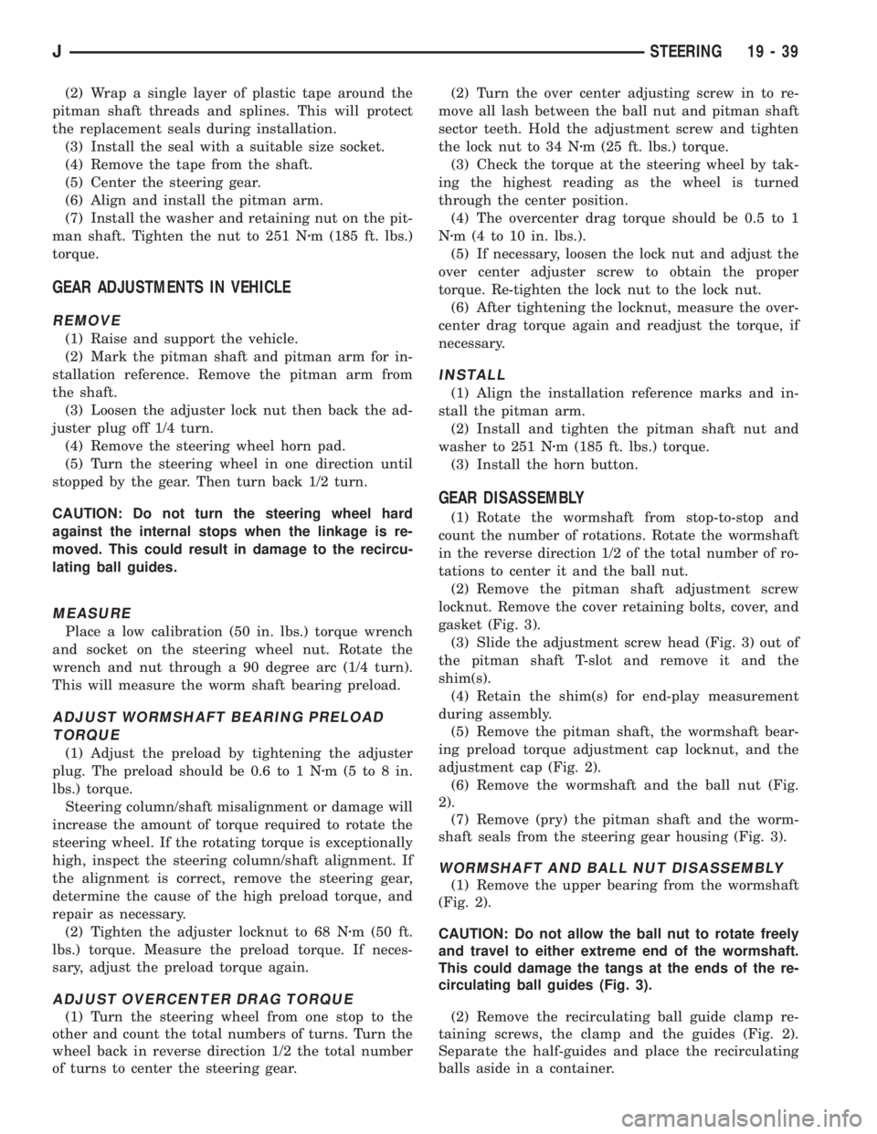
gasket (Fig. 3).
(3) Slide the adjustment screw head (Fig. 3) out of
the pitman shaft T-slot and remove it and the
shim(s).
(4) Retain the shim(s) for end-play measurement
during assembly.
(5) Remove the pitman shaft, the wormshaft bear-
ing preload torque adjustment cap locknut, and the
adjustment cap (Fig. 2).
(6) Remove the wormshaft and the ball nut (Fig.
2).
(7) Remove (pry) the pitman shaft and the worm-
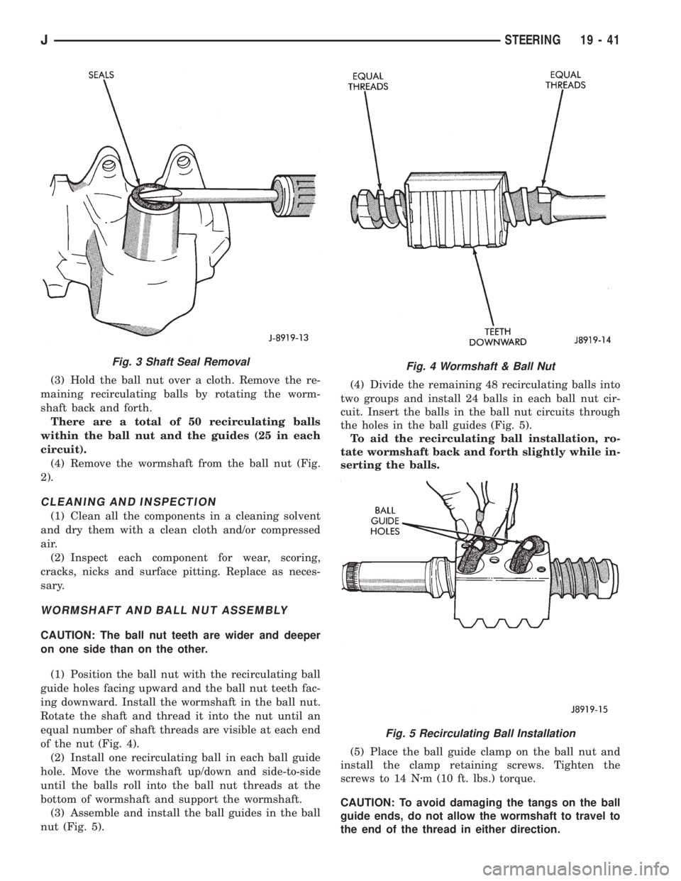
shaft seals from the steering gear housing (Fig. 3).
WORMSHAFT AND BALL NUT DISASSEMBLY
(1) Remove the upper bearing from the wormshaft
(Fig. 2).
CAUTION: Do not allow the ball nut to rotate freely
and travel to either extreme end of the wormshaft.
This could damage the tangs at the ends of the re-
circulating ball guides (Fig. 3).
(2) Remove the recirculating ball guide clamp re-
taining screws, the clamp and the guides (Fig. 2).
Separate the half-guides and place the recirculating
balls aside in a container.
JSTEERING 19 - 39
Page 1525 of 2158
(3) Hold the ball nut over a cloth. Remove the re-
maining recirculating balls by rotating the worm-
shaft back and forth.
There are a total of 50 recirculating balls
within the ball nut and the guides (25 in each
circuit).
(4) Remove the wormshaft from the ball nut (Fig.
2).
CLEANING AND INSPECTION
(1) Clean all the components in a cleaning solvent
and dry them with a clean cloth and/or compressed
air.
(2) Inspect each component for wear, scoring,
cracks, nicks and surface pitting. Replace as neces-
sary.
WORMSHAFT AND BALL NUT ASSEMBLY
CAUTION: The ball nut teeth are wider and deeper
on one side than on the other.
(1) Position the ball nut with the recirculating ball
guide holes facing upward and the ball nut teeth fac-
ing downward. Install the wormshaft in the ball nut.
Rotate the shaft and thread it into the nut until an
equal number of shaft threads are visible at each end
of the nut (Fig. 4).
(2) Install one recirculating ball in each ball guide
hole. Move the wormshaft up/down and side-to-side
until the balls roll into the ball nut threads at the
bottom of wormshaft and support the wormshaft.
(3) Assemble and install the ball guides in the ball
nut (Fig. 5).(4) Divide the remaining 48 recirculating balls into
two groups and install 24 balls in each ball nut cir-
cuit. Insert the balls in the ball nut circuits through
the holes in the ball guides (Fig. 5).
To aid the recirculating ball installation, ro-
tate wormshaft back and forth slightly while in-
serting the balls.
(5) Place the ball guide clamp on the ball nut and
install the clamp retaining screws. Tighten the
screws to 14 Nzm (10 ft. lbs.) torque.
CAUTION: To avoid damaging the tangs on the ball
guide ends, do not allow the wormshaft to travel to
the end of the thread in either direction.
Fig. 3 Shaft Seal RemovalFig. 4 Wormshaft & Ball Nut
Fig. 5 Recirculating Ball Installation
JSTEERING 19 - 41