1995 JEEP YJ battery
[x] Cancel search: batteryPage 1313 of 2158
tor in the Component Removal/Installation section of
Group 8D, Ignition Systems.
(14) Install the distributor and ignition wires. Re-
fer to Distributor in the Component Removal/Instal-
lation section of Group 8D, Ignition Systems.
(15) Install the radiator or radiator and condenser,
if equipped with A/C.
(16) Fill the cooling system.
(17) Connect negative cable to battery.
CAMSHAFT PIN REPLACEMENT
REMOVAL
WARNING: DO NOT LOOSEN THE RADIATOR
DRAIN COCK WITH THE SYSTEM HOT AND PRES-
SURIZED BECAUSE SERIOUS BURNS FROM COOL-
ANT CAN OCCUR.
(1) Disconnect negative cable from battery.
(2) Drain the radiator. DO NOT waste reusable
coolant. Drain the coolant into a clean container.
(3) Remove the fan and shroud.
(4) Disconnect the radiator overflow tube, radiator
hoses, automatic transmission fluid cooler pipes (if
equipped).
(5) Remove the radiator.
(6) If equipped with air conditioning:
CAUTION: DO NOT loosen or disconnect any air
conditioner system fittings. Move the condenser
and receiver/drier aside as a complete assembly.
(a) Remove the A/C compressor serpentine drive
belt idler pulley.
(b) Disconnect and remove the generator.
(c) Remove the A/C condenser attaching bolts
and move the condenser and receiver/drier assem-
bly up and out of the way.
(7) Remove the serpentine drive belt.
(8) Remove the crankshaft vibration damper.
(9) Remove the timing case cover. Clean the gasket
material from the cover.
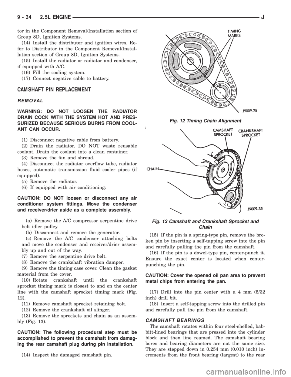
(10) Rotate crankshaft until the crankshaft
sprocket timing mark is closest to and on the center
line with the camshaft sprocket timing mark (Fig.
12).
(11) Remove camshaft sprocket retaining bolt.
(12) Remove the crankshaft oil slinger.
(13) Remove the sprockets and chain as an assem-
bly (Fig. 13).
CAUTION: The following procedural step must be
accomplished to prevent the camshaft from damag-
ing the rear camshaft plug during pin installation.
(14) Inspect the damaged camshaft pin.(15) If the pin is a spring-type pin, remove the bro-
ken pin by inserting a self-tapping screw into the pin
and carefully pulling the pin from the camshaft.
(16) If the pin is a dowel-type pin, center-punch it.
Ensure the exact center is located when center-
punching the pin.
CAUTION: Cover the opened oil pan area to prevent
metal chips from entering the pan.
(17) Drill into the pin center witha4mm(5/32
inch) drill bit.
(18) Insert a self-tapping screw into the drilled pin
and carefully pull the pin from the camshaft.
CAMSHAFT BEARINGS
The camshaft rotates within four steel-shelled, bab-
bitt-lined bearings that are pressed into the cylinder
block and then line reamed. The camshaft bearing
bores and bearing diameters are not the same size.
They are stepped down in 0.254 mm (0.010 inch) in-
crements from the front bearing (largest) to the rear
Fig. 12 Timing Chain Alignment
Fig. 13 Camshaft and Crankshaft Sprocket and
Chain
9 - 34 2.5L ENGINEJ
Page 1314 of 2158
bearing (smallest). This permits easier removal and
installation of the camshaft. The camshaft bearings
are pressure lubricated.
It is not advisable to attempt to replace cam-
shaft bearings unless special removal and in-
stallation tools are available.
Camshaft end play is maintained by the load
placed on the camshaft by the oil pump and distrib-
utor drive gear. The helical cut of the gear holds the
camshaft sprocket thrust face against the cylinder
block face.
INSTALLATION
(1) Clean the camshaft pin hole.
(2) Compress the center of the replacement spring
pin with vise grips.
(3) Carefully drive the pin into the camshaft pin
hole until it is seated.
(4) Install the camshaft sprocket, crankshaft
sprocket and timing chain with the timing marks
aligned (Fig. 12).
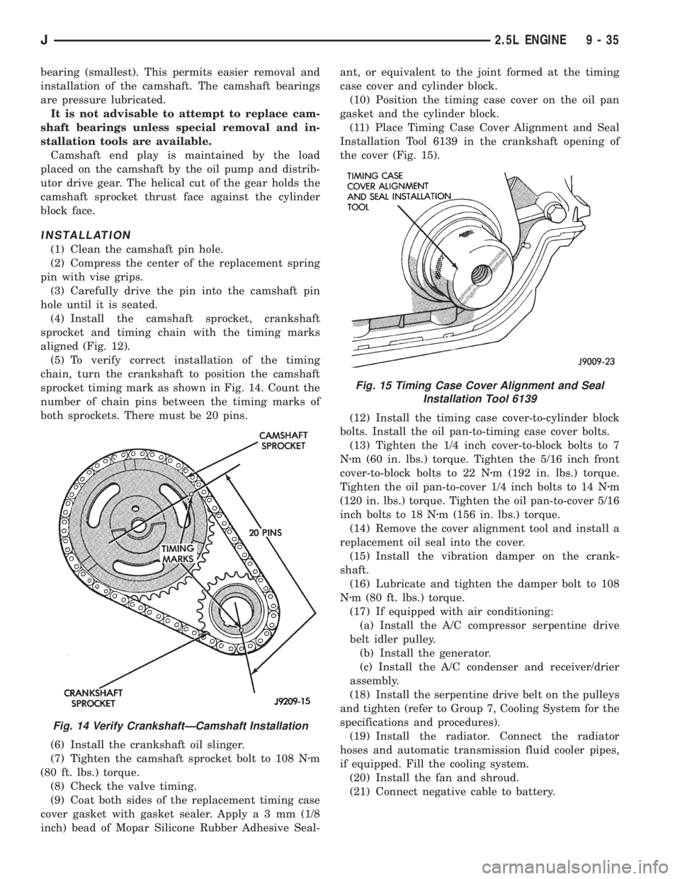
(5) To verify correct installation of the timing
chain, turn the crankshaft to position the camshaft
sprocket timing mark as shown in Fig. 14. Count the
number of chain pins between the timing marks of
both sprockets. There must be 20 pins.
(6) Install the crankshaft oil slinger.
(7) Tighten the camshaft sprocket bolt to 108 Nzm
(80 ft. lbs.) torque.
(8) Check the valve timing.
(9) Coat both sides of the replacement timing case
cover gasket with gasket sealer. Applya3mm(1/8
inch) bead of Mopar Silicone Rubber Adhesive Seal-ant, or equivalent to the joint formed at the timing
case cover and cylinder block.
(10) Position the timing case cover on the oil pan
gasket and the cylinder block.
(11) Place Timing Case Cover Alignment and Seal
Installation Tool 6139 in the crankshaft opening of
the cover (Fig. 15).
(12) Install the timing case cover-to-cylinder block
bolts. Install the oil pan-to-timing case cover bolts.
(13) Tighten the 1/4 inch cover-to-block bolts to 7
Nzm (60 in. lbs.) torque. Tighten the 5/16 inch front
cover-to-block bolts to 22 Nzm (192 in. lbs.) torque.
Tighten the oil pan-to-cover 1/4 inch bolts to 14 Nzm
(120 in. lbs.) torque. Tighten the oil pan-to-cover 5/16
inch bolts to 18 Nzm (156 in. lbs.) torque.
(14) Remove the cover alignment tool and install a
replacement oil seal into the cover.
(15) Install the vibration damper on the crank-
shaft.
(16) Lubricate and tighten the damper bolt to 108
Nzm (80 ft. lbs.) torque.
(17) If equipped with air conditioning:
(a) Install the A/C compressor serpentine drive
belt idler pulley.
(b) Install the generator.
(c) Install the A/C condenser and receiver/drier
assembly.
(18) Install the serpentine drive belt on the pulleys
and tighten (refer to Group 7, Cooling System for the
specifications and procedures).
(19) Install the radiator. Connect the radiator
hoses and automatic transmission fluid cooler pipes,
if equipped. Fill the cooling system.
(20) Install the fan and shroud.
(21) Connect negative cable to battery.
Fig. 14 Verify CrankshaftÐCamshaft Installation
Fig. 15 Timing Case Cover Alignment and Seal
Installation Tool 6139
J2.5L ENGINE 9 - 35
Page 1315 of 2158
OIL PAN
REMOVAL
(1) Disconnect negative cable from battery.
(2) Raise the vehicle.
(3) Remove the oil pan drain plug and drain the
engine oil.
(4) Disconnect the exhaust pipe at the engine ex-
haust manifold.
(5) Disconnect the exhaust hanger at the catalytic
converter and lower the pipe.
(6) Remove the engine starter motor.
(7) Remove the flywheel/torque converter housing
access cover.
(8) Position a jack stand directly under the engine
vibration damper.
(9) Place a piece of wood (2 x 2) between the jack
stand and the engine vibration damper.
(10) Remove the engine mount through bolts.
(11) Using the jack stand, raise the engine until
adequate clearance is obtained to remove the oil pan.
(12) Remove the oil pan bolts. Carefully remove
the oil pan and gasket.
CLEANING
Clean the block and pan gasket surfaces.
INSTALLATION
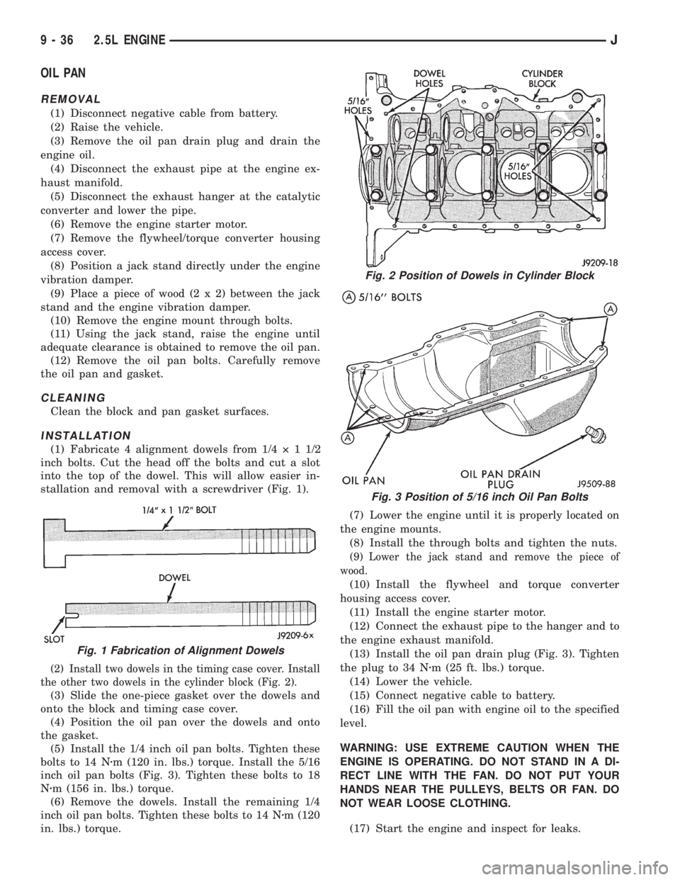
(1) Fabricate 4 alignment dowels from 1/4ý11/2
inch bolts. Cut the head off the bolts and cut a slot
into the top of the dowel. This will allow easier in-
stallation and removal with a screwdriver (Fig. 1).
(2) Install two dowels in the timing case cover. Install
the other two dowels in the cylinder block (Fig. 2).
(3) Slide the one-piece gasket over the dowels and
onto the block and timing case cover.
(4) Position the oil pan over the dowels and onto
the gasket.
(5) Install the 1/4 inch oil pan bolts. Tighten these
bolts to 14 Nzm (120 in. lbs.) torque. Install the 5/16
inch oil pan bolts (Fig. 3). Tighten these bolts to 18
Nzm (156 in. lbs.) torque.
(6) Remove the dowels. Install the remaining 1/4
inch oil pan bolts. Tighten these bolts to 14 Nzm (120
in. lbs.) torque.(7) Lower the engine until it is properly located on
the engine mounts.
(8) Install the through bolts and tighten the nuts.
(9) Lower the jack stand and remove the piece of
wood.
(10) Install the flywheel and torque converter
housing access cover.
(11) Install the engine starter motor.
(12) Connect the exhaust pipe to the hanger and to
the engine exhaust manifold.
(13) Install the oil pan drain plug (Fig. 3). Tighten
the plug to 34 Nzm (25 ft. lbs.) torque.
(14) Lower the vehicle.
(15) Connect negative cable to battery.
(16) Fill the oil pan with engine oil to the specified
level.
WARNING: USE EXTREME CAUTION WHEN THE
ENGINE IS OPERATING. DO NOT STAND IN A DI-
RECT LINE WITH THE FAN. DO NOT PUT YOUR
HANDS NEAR THE PULLEYS, BELTS OR FAN. DO
NOT WEAR LOOSE CLOTHING.
(17) Start the engine and inspect for leaks.
Fig. 1 Fabrication of Alignment Dowels
Fig. 2 Position of Dowels in Cylinder Block
Fig. 3 Position of 5/16 inch Oil Pan Bolts
9 - 36 2.5L ENGINEJ
Page 1324 of 2158
CAUTION: Verify that the oil squirt holes in the rods
face the camshaft and that the arrows on the pis-
tons face the front of the engine.
(7) Install the oil pan and gaskets as outlined in
the installation procedure.
(8) Lower the vehicle.
(9) Install the engine cylinder head, push rods,
rocker arms, bridges, pivots and engine cylinder head
cover.
(10) Fill the crankcase with engine oil.
CRANKSHAFT MAIN BEARINGS
REMOVAL
(1) Disconnect negative cable from battery.
(2) Remove the spark plugs.
(3) Raise the vehicle.
(4) Remove the oil pan and oil pump.
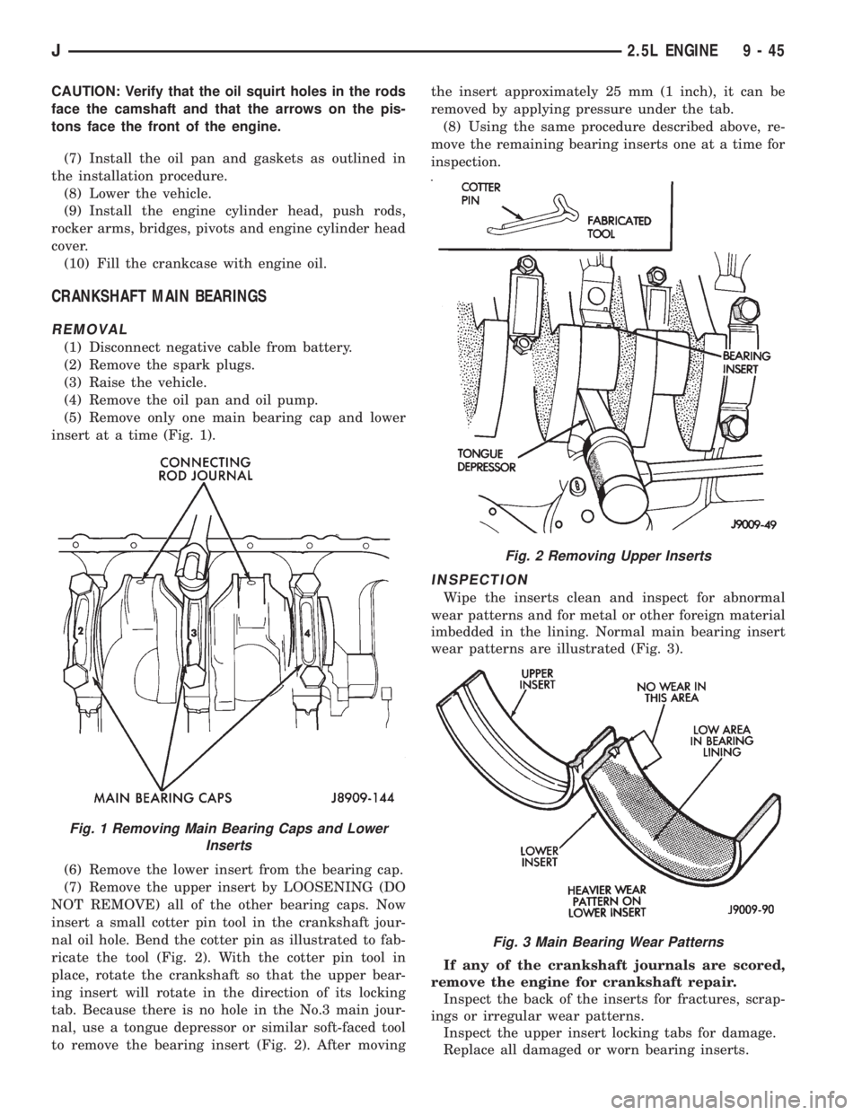
(5) Remove only one main bearing cap and lower
insert at a time (Fig. 1).
(6) Remove the lower insert from the bearing cap.
(7) Remove the upper insert by LOOSENING (DO
NOT REMOVE) all of the other bearing caps. Now
insert a small cotter pin tool in the crankshaft jour-
nal oil hole. Bend the cotter pin as illustrated to fab-
ricate the tool (Fig. 2). With the cotter pin tool in
place, rotate the crankshaft so that the upper bear-
ing insert will rotate in the direction of its locking
tab. Because there is no hole in the No.3 main jour-
nal, use a tongue depressor or similar soft-faced tool
to remove the bearing insert (Fig. 2). After movingthe insert approximately 25 mm (1 inch), it can be
removed by applying pressure under the tab.
(8) Using the same procedure described above, re-
move the remaining bearing inserts one at a time for
inspection.
INSPECTION
Wipe the inserts clean and inspect for abnormal
wear patterns and for metal or other foreign material
imbedded in the lining. Normal main bearing insert
wear patterns are illustrated (Fig. 3).
If any of the crankshaft journals are scored,
remove the engine for crankshaft repair.
Inspect the back of the inserts for fractures, scrap-
ings or irregular wear patterns.
Inspect the upper insert locking tabs for damage.
Replace all damaged or worn bearing inserts.
Fig. 1 Removing Main Bearing Caps and Lower
Inserts
Fig. 2 Removing Upper Inserts
Fig. 3 Main Bearing Wear Patterns
J2.5L ENGINE 9 - 45
Page 1328 of 2158
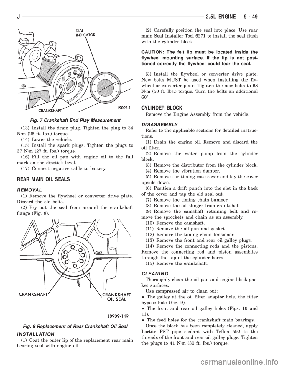
(13) Install the drain plug. Tighten the plug to 34
Nzm (25 ft. lbs.) torque.
(14) Lower the vehicle.
(15) Install the spark plugs. Tighten the plugs to
37 Nzm (27 ft. lbs.) torque.
(16) Fill the oil pan with engine oil to the full
mark on the dipstick level.
(17) Connect negative cable to battery.
REAR MAIN OIL SEALS
REMOVAL
(1) Remove the flywheel or converter drive plate.
Discard the old bolts.
(2) Pry out the seal from around the crankshaft
flange (Fig. 8).
INSTALLATION
(1) Coat the outer lip of the replacement rear main
bearing seal with engine oil.(2) Carefully position the seal into place. Use rear
main Seal Installer Tool 6271 to install the seal flush
with the cylinder block.
CAUTION: The felt lip must be located inside the
flywheel mounting surface. If the lip is not posi-
tioned correctly the flywheel could tear the seal.
(3) Install the flywheel or converter drive plate.
New bolts MUST be used when installing the fly-
wheel or converter plate. Tighten the new bolts to 68
Nzm (50 ft. lbs.) torque. Turn the bolts an additional
60É.
CYLINDER BLOCK
Remove the Engine Assembly from the vehicle.
DISASSEMBLY
Refer to the applicable sections for detailed instruc-
tions.
(1) Drain the engine oil. Remove and discard the
oil filter.
(2) Remove the water pump from the cylinder
block.
(3) Remove the distributor from the cylinder block.
(4) Remove the vibration damper.
(5) Remove the timing case cover and lay the cover
upside down.
(6) Position a drift punch into the slot in the back
of the cover and tap the old seal out.
(7) Remove the timing chain bumper.
(8) Remove the oil slinger from crankshaft.
(9) Remove the camshaft retaining bolt and re-
move the sprockets and chain as an assembly.
(10) Remove the camshaft.
(11) Remove the oil pan and gasket.
(12) Remove the timing chain tensioner.
(13) Remove the front and rear oil galley plugs.
(14) Remove the connecting rods and the pistons.
Remove the connecting rod and piston assemblies
through the top of the cylinder bores.
(15) Remove the crankshaft.
CLEANING
Thoroughly clean the oil pan and engine block gas-
ket surfaces.
Use compressed air to clean out:
²The galley at the oil filter adaptor hole, the filter
bypass hole (Fig. 9).
²The front and rear oil galley holes (Figs. 10 and
11).
²The feed holes for the crankshaft main bearings.
Once the block has been completely cleaned, apply
Loctite PST pipe sealant with Teflon 592 to the
threads of the front and rear oil galley plugs. Tighten
the plugs to 41 Nzm (30 ft. lbs.) torque.
Fig. 7 Crankshaft End Play Measurement
Fig. 8 Replacement of Rear Crankshaft Oil Seal
J2.5L ENGINE 9 - 49
Page 1335 of 2158
The digits of the code identify:
(1) 1st DigitÐThe year (4 = 1994).
(2) 2nd & 3rd DigitsÐThe month (01 - 12).
(3) 4th & 5th DigitsÐThe engine type/fuel system/
compression ratio (MX = A 4.0 Liter (242 CID) 8.7:1
compression ratio engine with a multi-point fuel in-
jection system).
(4) 6th & 7th DigitsÐThe day of engine build (01 -
31).
FOR EXAMPLE:Code * 401MX12 * identifies a
4.0 Liter (242 CID) engine with a multi-point fuel in-
jection system, 8.7:1 compression ratio and built on
January 12, 1994.
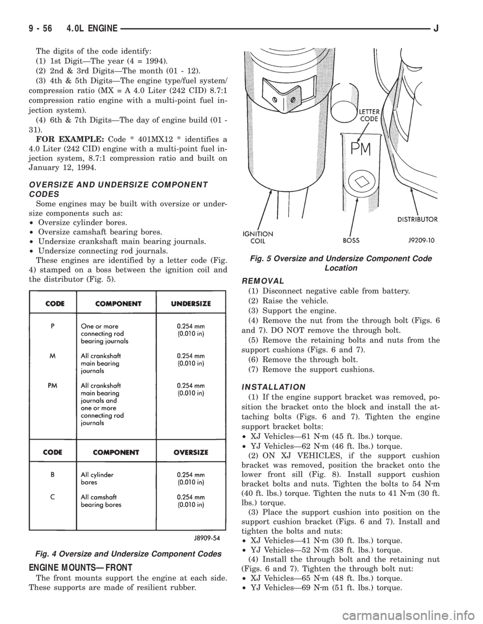
OVERSIZE AND UNDERSIZE COMPONENT
CODES
Some engines may be built with oversize or under-
size components such as:
²Oversize cylinder bores.
²Oversize camshaft bearing bores.
²Undersize crankshaft main bearing journals.
²Undersize connecting rod journals.
These engines are identified by a letter code (Fig.
4) stamped on a boss between the ignition coil and
the distributor (Fig. 5).
ENGINE MOUNTSÐFRONT
The front mounts support the engine at each side.
These supports are made of resilient rubber.
REMOVAL
(1) Disconnect negative cable from battery.
(2) Raise the vehicle.
(3) Support the engine.
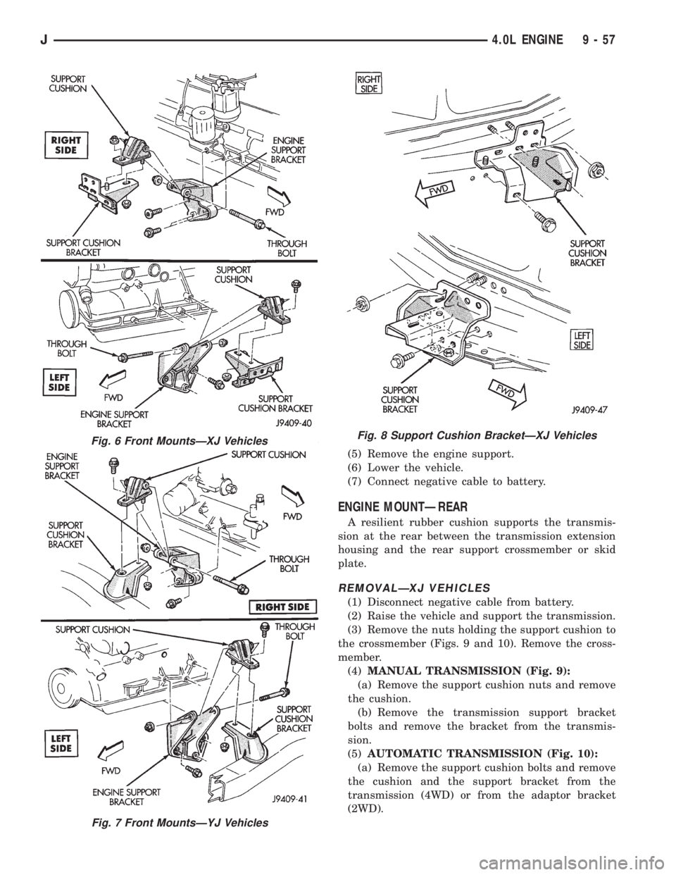
(4) Remove the nut from the through bolt (Figs. 6
and 7). DO NOT remove the through bolt.
(5) Remove the retaining bolts and nuts from the
support cushions (Figs. 6 and 7).
(6) Remove the through bolt.
(7) Remove the support cushions.
INSTALLATION
(1) If the engine support bracket was removed, po-
sition the bracket onto the block and install the at-
taching bolts (Figs. 6 and 7). Tighten the engine
support bracket bolts:
²XJ VehiclesÐ61 Nzm (45 ft. lbs.) torque.
²YJ VehiclesÐ62 Nzm (46 ft. lbs.) torque.
(2) ON XJ VEHICLES, if the support cushion
bracket was removed, position the bracket onto the
lower front sill (Fig. 8). Install support cushion
bracket bolts and nuts. Tighten the bolts to 54 Nzm
(40 ft. lbs.) torque. Tighten the nuts to 41 Nzm (30 ft.
lbs.) torque.
(3) Place the support cushion into position on the
support cushion bracket (Figs. 6 and 7). Install and
tighten the bolts and nuts:
²XJ VehiclesÐ41 Nzm (30 ft. lbs.) torque.
²YJ VehiclesÐ52 Nzm (38 ft. lbs.) torque.
(4) Install the through bolt and the retaining nut
(Figs. 6 and 7). Tighten the through bolt nut:
²XJ VehiclesÐ65 Nzm (48 ft. lbs.) torque.
²YJ VehiclesÐ69 Nzm (51 ft. lbs.) torque.
Fig. 4 Oversize and Undersize Component Codes
Fig. 5 Oversize and Undersize Component Code
Location
9 - 56 4.0L ENGINEJ
Page 1336 of 2158
(5) Remove the engine support.
(6) Lower the vehicle.
(7) Connect negative cable to battery.
ENGINE MOUNTÐREAR
A resilient rubber cushion supports the transmis-
sion at the rear between the transmission extension
housing and the rear support crossmember or skid
plate.
REMOVALÐXJ VEHICLES
(1) Disconnect negative cable from battery.
(2) Raise the vehicle and support the transmission.
(3) Remove the nuts holding the support cushion to
the crossmember (Figs. 9 and 10). Remove the cross-
member.
(4)MANUAL TRANSMISSION (Fig. 9):
(a) Remove the support cushion nuts and remove
the cushion.
(b) Remove the transmission support bracket
bolts and remove the bracket from the transmis-
sion.
(5)AUTOMATIC TRANSMISSION (Fig. 10):
(a) Remove the support cushion bolts and remove
the cushion and the support bracket from the
transmission (4WD) or from the adaptor bracket
(2WD).
Fig. 6 Front MountsÐXJ Vehicles
Fig. 7 Front MountsÐYJ Vehicles
Fig. 8 Support Cushion BracketÐXJ Vehicles
J4.0L ENGINE 9 - 57
Page 1337 of 2158
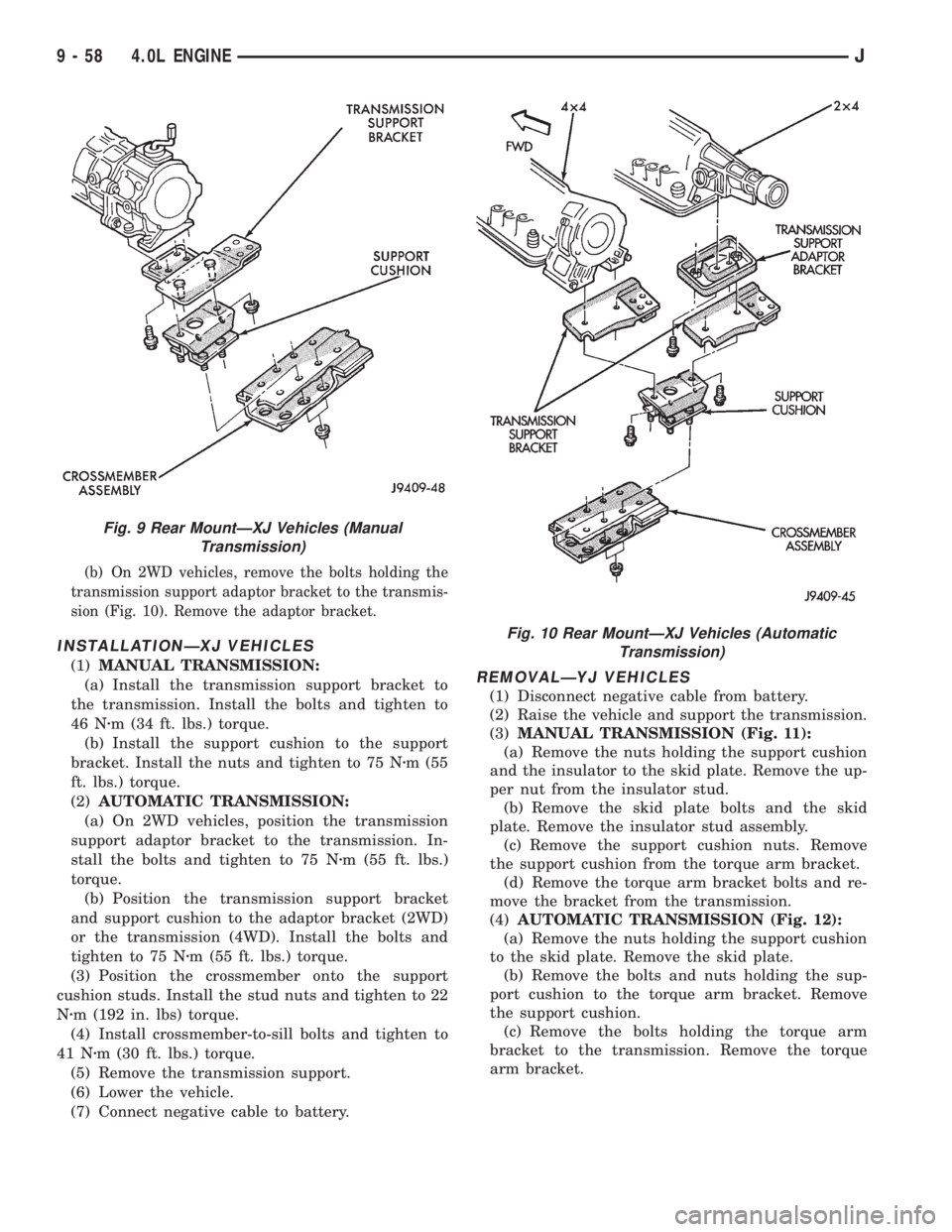
(b) On 2WD vehicles, remove the bolts holding the
transmission support adaptor bracket to the transmis-
sion (Fig. 10). Remove the adaptor bracket.
INSTALLATIONÐXJ VEHICLES
(1)MANUAL TRANSMISSION:
(a) Install the transmission support bracket to
the transmission. Install the bolts and tighten to
46 Nzm (34 ft. lbs.) torque.
(b) Install the support cushion to the support
bracket. Install the nuts and tighten to 75 Nzm (55
ft. lbs.) torque.
(2)AUTOMATIC TRANSMISSION:
(a) On 2WD vehicles, position the transmission
support adaptor bracket to the transmission. In-
stall the bolts and tighten to 75 Nzm (55 ft. lbs.)
torque.
(b) Position the transmission support bracket
and support cushion to the adaptor bracket (2WD)
or the transmission (4WD). Install the bolts and
tighten to 75 Nzm (55 ft. lbs.) torque.
(3) Position the crossmember onto the support
cushion studs. Install the stud nuts and tighten to 22
Nzm (192 in. lbs) torque.
(4) Install crossmember-to-sill bolts and tighten to
41 Nzm (30 ft. lbs.) torque.
(5) Remove the transmission support.
(6) Lower the vehicle.
(7) Connect negative cable to battery.REMOVALÐYJ VEHICLES
(1) Disconnect negative cable from battery.
(2) Raise the vehicle and support the transmission.
(3)MANUAL TRANSMISSION (Fig. 11):
(a) Remove the nuts holding the support cushion
and the insulator to the skid plate. Remove the up-
per nut from the insulator stud.
(b) Remove the skid plate bolts and the skid
plate. Remove the insulator stud assembly.
(c) Remove the support cushion nuts. Remove
the support cushion from the torque arm bracket.
(d) Remove the torque arm bracket bolts and re-
move the bracket from the transmission.
(4)AUTOMATIC TRANSMISSION (Fig. 12):
(a) Remove the nuts holding the support cushion
to the skid plate. Remove the skid plate.
(b) Remove the bolts and nuts holding the sup-
port cushion to the torque arm bracket. Remove
the support cushion.
(c) Remove the bolts holding the torque arm
bracket to the transmission. Remove the torque
arm bracket.
Fig. 9 Rear MountÐXJ Vehicles (Manual
Transmission)
Fig. 10 Rear MountÐXJ Vehicles (Automatic
Transmission)
9 - 58 4.0L ENGINEJ