1995 JEEP YJ Rear End Gear Oil
[x] Cancel search: Rear End Gear OilPage 1564 of 2158
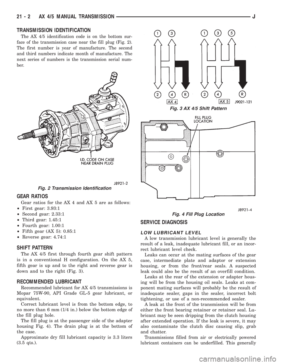
TRANSMISSION IDENTIFICATION
The AX 4/5 identification code is on the bottom sur-
face of the transmission case near the fill plug (Fig. 2).
The first number is year of manufacture. The second
and third numbers indicate month of manufacture. The
next series of numbers is the transmission serial num-
ber.
GEAR RATIOS
Gear ratios for the AX 4 and AX 5 are as follows:
²First gear: 3.93:1
²Second gear: 2.33:1
²Third gear: 1.45:1
²Fourth gear: 1.00:1
²Fifth gear (AX 5): 0.85:1
²Reverse gear: 4.74:1
SHIFT PATTERN
The AX 4/5 first through fourth gear shift pattern
is in a conventional H configuration. On the AX 5,
fifth gear is up and to the right and reverse gear is
down and to the right (Fig. 3).
RECOMMENDED LUBRICANT
Recommended lubricant for AX 4/5 transmissions is
Mopar 75W-90, API Grade GL-5 gear lubricant, or
equivalent.
Correct lubricant level is from the bottom edge, to
no more than 6 mm (1/4 in.) below the bottom edge of
the fill plug hole.
The fill plug is at the passenger side of the adapter
housing Fig. 4). The drain plug is at the bottom of
the case.
Approximate dry fill lubricant capacity is 3.3 liters
(3.5 qts.).
SERVICE DIAGNOSIS
LOW LUBRICANT LEVEL
A low transmission lubricant level is generally the
result of a leak, inadequate lubricant fill, or an incor-
rect lubricant level check.
Leaks can occur at the mating surfaces of the gear
case, intermediate plate and adaptor or extension
housing, or from the front/rear seals. A suspected
leak could also be the result of an overfill condition.
Leaks at the rear of the extension or adapter hous-
ing will be from the housing oil seals. Leaks at com-
ponent mating surfaces will probably be the result of
inadequate sealer, gaps in the sealer, incorrect bolt
tightening, or use of a non-recommended sealer.
A leak at the front of the transmission will be from
either the front bearing retainer or retainer seal. Lu-
bricant may be seen dripping from the clutch housing
after extended operation. If the leak is severe, it may
also contaminate the clutch disc causing slip, grab
and chatter.
Transmissions filled from air or electrically powered
lubricant containers can be underfilled. This generally
Fig. 2 Transmission Identification
Fig. 3 AX 4/5 Shift Pattern
Fig. 4 Fill Plug Location
21 - 2 AX 4/5 MANUAL TRANSMISSIONJ
Page 1565 of 2158

happens when the container delivery mechanism is im-
properly calibrated. Always check the lubricant level af-
ter filling to avoid an under fill condition.
A correct lubricant level check can only be made
when the vehicle is level; use a drive-on hoist to en-
sure this. Also allow the lubricant to settle for a
minute or so before checking. These recommenda-
tions will ensure an accurate check and avoid an un-
der-or-overfill condition.
HARD SHIFTING
Hard shifting is usually caused by a low lubricant
level, improper or contaminated lubricants, compo-
nent damage, incorrect clutch adjustment, or by a
damaged clutch pressure plate or disc.
Substantial lubricant leaks can result in gear, shift
rail, synchro and bearing damage. If a leak goes un-
detected for an extended period, the first indications
of a problem are usually hard shifting and noise.
Incorrect or contaminated lubricants can also con-
tribute to hard shifting. The consequence of using
non-recommended lubricants is noise, excessive wear,
internal bind and hard shifting.
Improper clutch release is a frequent cause of hard
shifting. Incorrect adjustment or a worn, damaged
pressure plate or disc can cause incorrect release. If
the clutch problem is advanced, gear clash during
shifts can result.
Worn or damaged synchro rings can cause gear clash
when shifting into any forward gear. In some new or re-
built transmissions, new synchro rings may tend to
stick slightly causing hard or noisy shifts. In most
cases, this condition will decline as the rings wear-in.
TRANSMISSION NOISE
Most manual transmissions make some noise dur-
ing normal operation. Rotating gears generate a mild
whine that is audible but only at extreme speeds.
Severe, highly audible transmission noise is gener-
ally the result of a lubricant problem. Insufficient,
improper, or contaminated lubricant will promote
rapid wear of gears, synchros, shift rails, forks and
bearings. The overheating caused by a lubricant
problem, can also lead to gear breakage.
TRANSMISSION REMOVAL
(1) Shift transmission into first or third gear. Then
raise vehicle on hoist.
(2) Support engine with adjustable jack stand. Po-
sition wood block between jack and oil pan to avoid
damaging pan.
(3) Disconnect necessary exhaust system components.
(4) Remove skid plate.
(5) Disconnect rear cushion and bracket from
transmission (Fig. 5).
(6) Remove rear crossmember.
Fig. 5 Rear Mount Components (YJ Shown)
JAX 4/5 MANUAL TRANSMISSION 21 - 3
Page 1596 of 2158
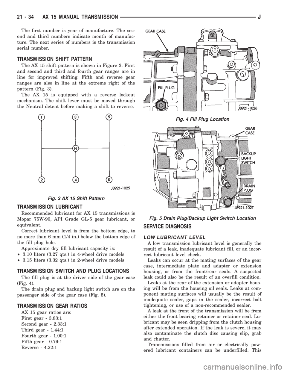
The first number is year of manufacture. The sec-
ond and third numbers indicate month of manufac-
ture. The next series of numbers is the transmission
serial number.
TRANSMISSION SHIFT PATTERN
The AX 15 shift pattern is shown in Figure 3. First
and second and third and fourth gear ranges are in
line for improved shifting. Fifth and reverse gear
ranges are also in line at the extreme right of the
pattern (Fig. 3).
The AX 15 is equipped with a reverse lockout
mechanism. The shift lever must be moved through
the Neutral detent before making a shift to reverse.
TRANSMISSION LUBRICANT
Recommended lubricant for AX 15 transmissions is
Mopar 75W-90, API Grade GL-5 gear lubricant, or
equivalent.
Correct lubricant level is from the bottom edge, to
no more than 6 mm (1/4 in.) below the bottom edge of
the fill plug hole.
Approximate dry fill lubricant capacity is:
²3.10 liters (3.27 qts.) in 4-wheel drive models
²3.15 liters (3.32 qts.) in 2-wheel drive models
TRANSMISSION SWITCH AND PLUG LOCATIONS
The fill plug is at the driver side of the gear case
(Fig. 4).
The drain plug and backup light switch are on the
passenger side of the gear case (Fig. 5).
TRANSMISSION GEAR RATIOS
AX 15 gear ratios are:
First gear - 3.83:1
Second gear - 2.33:1
Third gear - 1.44:1
Fourth gear - 1.00:1
Fifth gear - 0.79:1
Reverse - 4.22:1
SERVICE DIAGNOSIS
LOW LUBRICANT LEVEL
A low transmission lubricant level is generally the
result of a leak, inadequate lubricant fill, or an incor-
rect lubricant level check.
Leaks can occur at the mating surfaces of the gear
case, intermediate plate and adapter or extension
housing, or from the front/rear seals. A suspected
leak could also be the result of an overfill condition.
Leaks at the rear of the extension or adapter hous-
ing will be from the housing oil seals. Leaks at com-
ponent mating surfaces will usually be the result of
inadequate sealer, gaps in the sealer, incorrect bolt
tightening, or use of a non-recommended sealer.
A leak at the front of the transmission will be from
either the front bearing retainer or retainer seal. Lu-
bricant may be seen dripping from the clutch housing
after extended operation. If the leak is severe, it may
also contaminate the clutch disc causing slip, grab
and chatter.
Transmissions filled from air or electrically pow-
ered lubricant containers can be underfilled. This
Fig. 3 AX 15 Shift Pattern
Fig. 4 Fill Plug Location
Fig. 5 Drain Plug/Backup Light Switch Location
21 - 34 AX 15 MANUAL TRANSMISSIONJ
Page 1661 of 2158
30RH/32RH IN-VEHICLE SERVICE
INDEX
page page
Converter Drainback Check Valve Service...... 113
Fluid and Filter Replacement................. 99
Fluid Level Check......................... 99
Front Band Adjustment.................... 102
Governor and Park Gear Service............. 105
Oil Filter Replacement..................... 103
Park Interlock Cable Adjustment (XJ).......... 101
Park Lock Component Replacement.......... 108
Park/Neutral Position Switch Service.......... 109
Rear Band Adjustment.................... 103
Recommended Fluid....................... 99Refilling After Overhaul or Fluid/Filter Change . . . 100
Shift Cable Adjustment (XJ)................. 100
Shift Linkage Adjustment (YJ)............... 100
Speedometer Service..................... 109
Throttle Valve Cable Adjustment (XJ/YJ)....... 101
Transmission Cooler Flow Testing............ 113
Transmission Cooler Line and Fitting Service.... 111
Transmission Cooler Reverse Flushing......... 114
Valve Body Installation.................... 104
Valve Body Removal...................... 104
Valve Body Service....................... 104
RECOMMENDED FLUID
Recommended (and preferred) fluid for 30RH/32RH
transmissions is Mopar ATF Plus, type 7176.
Dexron II is not really recommended and should
only be used when ATF Plus is not available.
FLUID LEVEL CHECK
Transmission fluid level should be checked monthly
under normal operation. If the vehicle is used for
trailer towing or similar heavy load hauling, check
fluid level and condition weekly.
Fluid level is checked with the engine running at
curb idle speed, the transmission in Neutral and the
transmission fluid at normal operating temperature.
FLUID LEVEL CHECK PROCEDURE
(1) Transmission fluid must be at normal operating
temperature for accurate fluid level check. Drive ve-
hicle if necessary to bring fluid temperature up to
normal hot operating temperature of 82ÉC (180ÉF).
(2) Position vehicle on level surface. This is ex-
tremely important for accurate fluid level check.
(3) Start and run engine at curb idle speed.
(4) Apply parking brakes.
(5) Shift transmission momentarily into all gear
ranges. Then shift transmission back to Neutral.
(6) Clean top of filler tube and dipstick to keep dirt
from entering tube.
(7) Remove dipstick and check fluid level as fol-
lows:
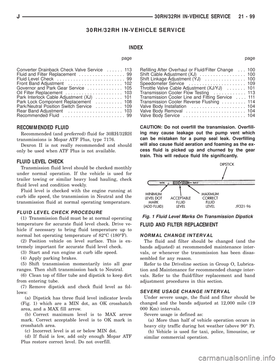
(a) Dipstick has three fluid level indicator levels
(Fig. 1) which are a MIN dot, an OK crosshatch
area, and a MAX fill arrow.
(b) Correct maximum level is to MAX arrow
mark. Correct acceptable level is to OK mark in
crosshatch area.
(c) Incorrect level is at or below MIN dot.
(d) If fluid is low, add only enough Mopar ATF
Plus restore correct level. Do not overfill.CAUTION: Do not overfill the transmission. Overfill-
ing may cause leakage out the pump vent which
can be mistaken for a pump seal leak. Overfilling
will also cause fluid aeration and foaming as the ex-
cess fluid is picked up and churned by the gear
train. This will reduce fluid life significantly.
FLUID AND FILTER REPLACEMENT
NORMAL CHANGE INTERVAL
The fluid and filter should be changed (and the
bands adjusted) at recommended maintenance inter-
vals, or whenever the transmission has been disas-
sembled for any reason.
Refer to the Driveline section in Group O, Lubrica-
tion and Maintenance for recommended change inter-
vals. Refer to the fluid/filter replacement and band
adjustment procedures in this section.
SEVERE USAGE CHANGE INTERVAL
Under severe usage, the fluid and filter should be
changed and the bands adjusted at 12,000 mile (19
000 Km) intervals.
Severe usage is defined as:
(a) More than half of vehicle operation occurs in
heavy city traffic during hot weather (above 90É F).
(b) Vehicle is used for taxi, police, limousine, or
similar commercial operation.
Fig. 1 Fluid Level Marks On Transmission Dipstick
J30RH/32RH IN-VEHICLE SERVICE 21 - 99
Page 1662 of 2158
(c) Vehicle is used for trailer towing or heavy
load hauling.
FLUID/FILTER REPLACEMENT PROCEDURE
(1) Raise vehicle.
(2) Remove oil pan and drain fluid.
(3) Clean oil pan and pan magnet. Then clean re-
maining gasket material from gasket surface of
transmission case.
(4) Remove fluid filter screws and remove filter.
(5) Position new filter on valve body and install fil-
ter screws. Tighten screws to 4 Nzm (35 in. lbs.)
torque.
(6) Adjust rear band at this time if required.
(7) Position new gasket on oil pan and install pan
on transmission. Tighten pan bolts to 150 in. lbs. (17
Nzm) torque.
(8) Adjust front band at this time if required.
(9) Lower vehicle and refill transmission with Mo-
par ATF Plus, type 7176 fluid.
REFILLING AFTER OVERHAUL OR FLUID/FILTER
CHANGE
The most effective way to avoid overfilling after a
fluid change or overhaul is as follows:
(1) Remove dipstick and insert clean funnel in
transmission fill tube.
(2) Add following initial quantity of Mopar ATF
Plus to transmission:
(a) If only fluid and filter were changed, add3
pints (1-1/2 quarts)of ATF Plus to transmission.
(b) If transmission was completely overhauled
and torque converter was replaced or drained, add
10 pints (5 quarts)of ATF Plus to transmission.
(3) Apply parking brakes.
(4) Start and run engine at normal curb idle speed.
(5) Apply service brakes, shift transmission
through all gear ranges then back to Neutral, and
leave engine running at curb idle speed.
(6) Remove funnel, insert dipstick and check fluid
level. Add only enough fluid to bring level toMIN
dot mark on dipstick.
(7) Drive vehicle until transmission fluid is at nor-
mal operating temperature. Then recheck fluid level
as described in next step.
(8) Leave engine running at curb idle speed, shift
into Neutral, and check fluid level again. This time,
add just enough fluid to bring level up toMAX ar-
row mark but do not overfill.
(9) When fluid level is correct, shut engine off, re-
lease park brake, remove funnel, and reseat dipstick
in fill tube.
SHIFT LINKAGE ADJUSTMENT (YJ)
(1) Check linkage adjustment by starting engine in
Park and Neutral.(2) Adjustment is OK if engine starts only in park
and Neutral. Adjustment is incorrect if engine starts
in one but not both positions.
(3) If engine starts in any position other than Park
or Neutral, or if engine will not start at all, park/
neutral position switch may be faulty.
(4) Shift transmission into Park.
(5) Raise vehicle.
(6) Check condition of shift rods, bellcrank,
bellcrank brackets and linkage bushings/grommets
(Fig. 2). Tighten, repair, replace worn, damaged
parts. Do not attempt adjustment if linkage compo-
nents are worn or damaged.
(7) Loosen shift rod trunnion lock bolt or nut. Be
sure upper shift rod slides freely in trunnion (Fig. 2).
Also be sure shift rods and bellcrank rotate freely
and do not bind at any point.
(8) Verify that manual lever is in Park detent (Fig.
2). Move lever all the way rearward to be sure it is in
Park.
(9) Check for positive engagement of park lock by
attempting to rotate propeller shaft. Shaft will not
turn when park pawl is engaged.
(10) Adjust shift rod trunnion to a obtain free pin
fit in bellcrank arm and tighten trunnion lock bolt or
nut. Prevent shift rod from turning while tightening
bolt or nut. Gearshift linkage lash must be elimi-
nated to obtain proper adjustment. Eliminate lash by
pulling downward on shift rod and pressing upward
on bellcrank.
(11) Confirm proper adjustment by starting engine
in Park and Neutral. Engine should start in these
positions only.If engine starts in any position
other than Park or Neutral, adjustment is in-
correct or neutral switch is faulty.
(12) Lower vehicle and verify that steering lock op-
erates correctly.
SHIFT CABLE ADJUSTMENT (XJ)
(1) Shift transmission into Park.
(2) Raise vehicle.
(3) Release cable adjuster clamp to unlock cable
(Figs. 3 and 4). Clamp is at transmission end of ca-
ble.
(4) Unsnap cable from transmission cable bracket.
(5) Move transmission shift lever fully rearward to
Park detent. Lever is on manual valve shaft at driver
side of case.
(6) Verify positive engagement of park lock by at-
tempting to rotate propeller shaft. Shaft will not ro-
tate when park lock is engaged.
(7) Snap cable into cable bracket.
(8) Lock shift cable by pressing cable adjuster
clamp down until it snaps into place.
(9) Check engine starting. Engine should start only
in Park and Neutral.
(10) Lower vehicle.
21 - 100 30RH/32RH IN-VEHICLE SERVICEJ
Page 1667 of 2158
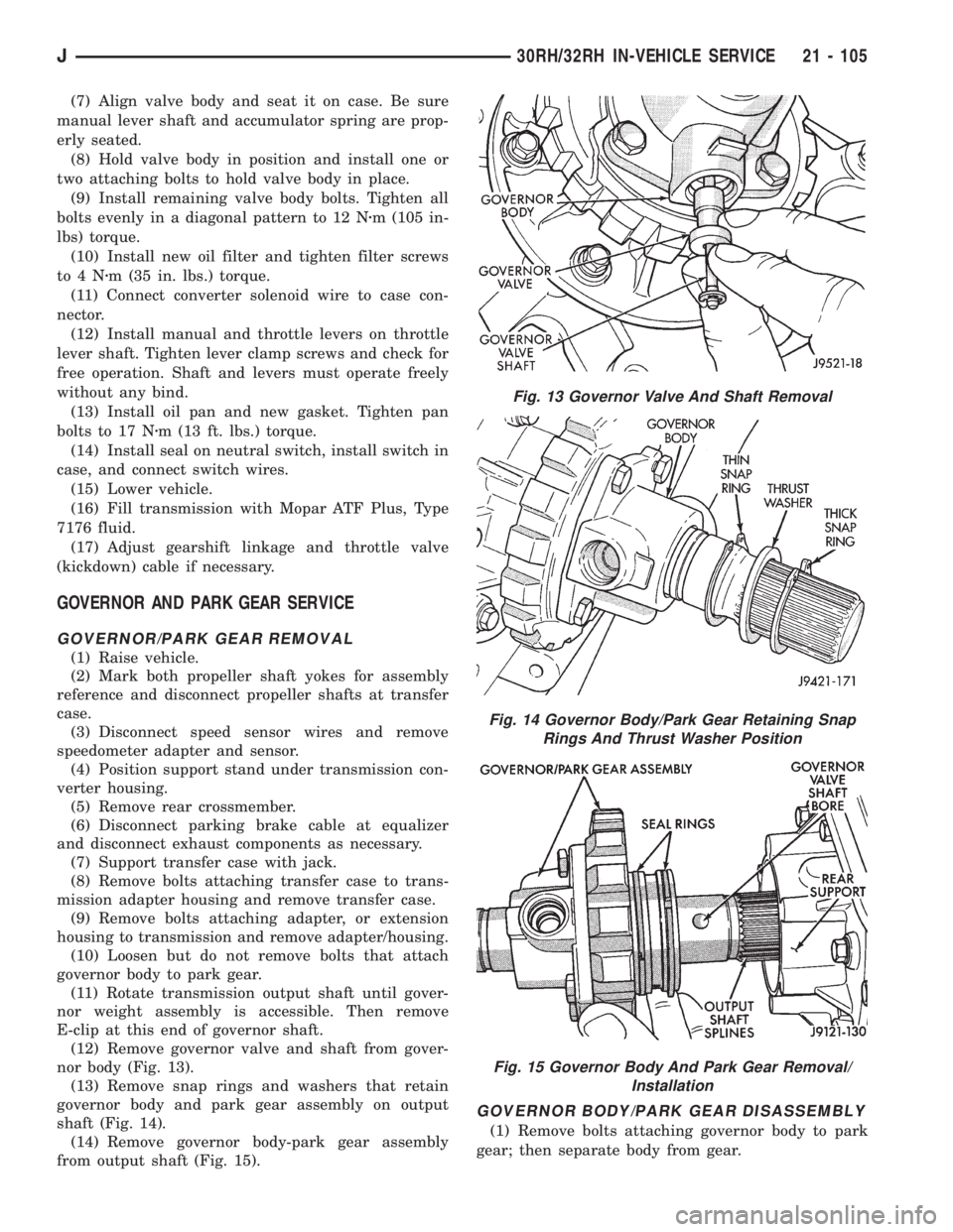
(7) Align valve body and seat it on case. Be sure
manual lever shaft and accumulator spring are prop-
erly seated.
(8) Hold valve body in position and install one or
two attaching bolts to hold valve body in place.
(9) Install remaining valve body bolts. Tighten all
bolts evenly in a diagonal pattern to 12 Nzm (105 in-
lbs) torque.
(10) Install new oil filter and tighten filter screws
to4Nzm (35 in. lbs.) torque.
(11) Connect converter solenoid wire to case con-
nector.
(12) Install manual and throttle levers on throttle
lever shaft. Tighten lever clamp screws and check for
free operation. Shaft and levers must operate freely
without any bind.
(13) Install oil pan and new gasket. Tighten pan
bolts to 17 Nzm (13 ft. lbs.) torque.
(14) Install seal on neutral switch, install switch in
case, and connect switch wires.
(15) Lower vehicle.
(16) Fill transmission with Mopar ATF Plus, Type
7176 fluid.
(17) Adjust gearshift linkage and throttle valve
(kickdown) cable if necessary.
GOVERNOR AND PARK GEAR SERVICE
GOVERNOR/PARK GEAR REMOVAL
(1) Raise vehicle.
(2) Mark both propeller shaft yokes for assembly
reference and disconnect propeller shafts at transfer
case.
(3) Disconnect speed sensor wires and remove
speedometer adapter and sensor.
(4) Position support stand under transmission con-
verter housing.
(5) Remove rear crossmember.
(6) Disconnect parking brake cable at equalizer
and disconnect exhaust components as necessary.
(7) Support transfer case with jack.
(8) Remove bolts attaching transfer case to trans-
mission adapter housing and remove transfer case.
(9) Remove bolts attaching adapter, or extension
housing to transmission and remove adapter/housing.
(10) Loosen but do not remove bolts that attach
governor body to park gear.
(11) Rotate transmission output shaft until gover-
nor weight assembly is accessible. Then remove
E-clip at this end of governor shaft.
(12) Remove governor valve and shaft from gover-
nor body (Fig. 13).
(13) Remove snap rings and washers that retain
governor body and park gear assembly on output
shaft (Fig. 14).
(14) Remove governor body-park gear assembly
from output shaft (Fig. 15).
GOVERNOR BODY/PARK GEAR DISASSEMBLY
(1) Remove bolts attaching governor body to park
gear; then separate body from gear.
Fig. 13 Governor Valve And Shaft Removal
Fig. 14 Governor Body/Park Gear Retaining Snap
Rings And Thrust Washer Position
Fig. 15 Governor Body And Park Gear Removal/
Installation
J30RH/32RH IN-VEHICLE SERVICE 21 - 105
Page 1687 of 2158
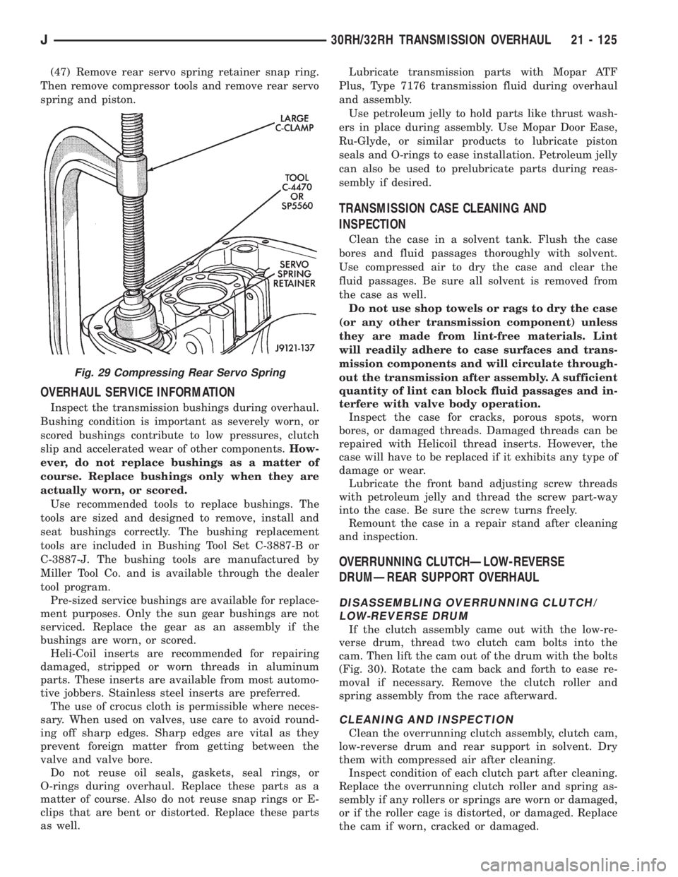
(47) Remove rear servo spring retainer snap ring.
Then remove compressor tools and remove rear servo
spring and piston.
OVERHAUL SERVICE INFORMATION
Inspect the transmission bushings during overhaul.
Bushing condition is important as severely worn, or
scored bushings contribute to low pressures, clutch
slip and accelerated wear of other components.How-
ever, do not replace bushings as a matter of
course. Replace bushings only when they are
actually worn, or scored.
Use recommended tools to replace bushings. The
tools are sized and designed to remove, install and
seat bushings correctly. The bushing replacement
tools are included in Bushing Tool Set C-3887-B or
C-3887-J. The bushing tools are manufactured by
Miller Tool Co. and is available through the dealer
tool program.
Pre-sized service bushings are available for replace-
ment purposes. Only the sun gear bushings are not
serviced. Replace the gear as an assembly if the
bushings are worn, or scored.
Heli-Coil inserts are recommended for repairing
damaged, stripped or worn threads in aluminum
parts. These inserts are available from most automo-
tive jobbers. Stainless steel inserts are preferred.
The use of crocus cloth is permissible where neces-
sary. When used on valves, use care to avoid round-
ing off sharp edges. Sharp edges are vital as they
prevent foreign matter from getting between the
valve and valve bore.
Do not reuse oil seals, gaskets, seal rings, or
O-rings during overhaul. Replace these parts as a
matter of course. Also do not reuse snap rings or E-
clips that are bent or distorted. Replace these parts
as well.Lubricate transmission parts with Mopar ATF
Plus, Type 7176 transmission fluid during overhaul
and assembly.
Use petroleum jelly to hold parts like thrust wash-
ers in place during assembly. Use Mopar Door Ease,
Ru-Glyde, or similar products to lubricate piston
seals and O-rings to ease installation. Petroleum jelly
can also be used to prelubricate parts during reas-
sembly if desired.
TRANSMISSION CASE CLEANING AND
INSPECTION
Clean the case in a solvent tank. Flush the case
bores and fluid passages thoroughly with solvent.
Use compressed air to dry the case and clear the
fluid passages. Be sure all solvent is removed from
the case as well.
Do not use shop towels or rags to dry the case
(or any other transmission component) unless
they are made from lint-free materials. Lint
will readily adhere to case surfaces and trans-
mission components and will circulate through-
out the transmission after assembly. A sufficient
quantity of lint can block fluid passages and in-
terfere with valve body operation.
Inspect the case for cracks, porous spots, worn
bores, or damaged threads. Damaged threads can be
repaired with Helicoil thread inserts. However, the
case will have to be replaced if it exhibits any type of
damage or wear.
Lubricate the front band adjusting screw threads
with petroleum jelly and thread the screw part-way
into the case. Be sure the screw turns freely.
Remount the case in a repair stand after cleaning
and inspection.
OVERRUNNING CLUTCHÐLOW-REVERSE
DRUMÐREAR SUPPORT OVERHAUL
DISASSEMBLING OVERRUNNING CLUTCH/
LOW-REVERSE DRUM
If the clutch assembly came out with the low-re-
verse drum, thread two clutch cam bolts into the
cam. Then lift the cam out of the drum with the bolts
(Fig. 30). Rotate the cam back and forth to ease re-
moval if necessary. Remove the clutch roller and
spring assembly from the race afterward.
CLEANING AND INSPECTION
Clean the overrunning clutch assembly, clutch cam,
low-reverse drum and rear support in solvent. Dry
them with compressed air after cleaning.
Inspect condition of each clutch part after cleaning.
Replace the overrunning clutch roller and spring as-
sembly if any rollers or springs are worn or damaged,
or if the roller cage is distorted, or damaged. Replace
the cam if worn, cracked or damaged.
Fig. 29 Compressing Rear Servo Spring
J30RH/32RH TRANSMISSION OVERHAUL 21 - 125
Page 1692 of 2158
if damaged. Inspect the park gear for chipped or
worn gear teeth or damaged ring grooves. Replace
the gear, if damaged.
Check the teeth on the park gear for wear or dam-
age. Replace the gear if necessary. Inspect the metal
seal rings on the park gear hub. Replace the rings
only if severely worn, or broken.
Minor scratches, or burrs on governor components
can be cleaned up with oil-soaked crocus cloth. How-
ever, do not attempt to salvage components that are
severely worn or scored.
The governor valve is made of aluminum and
the output shaft has been spotfaced to accept
the valve. The aluminum valve must not be
used in prior transmissions. The valve can only
be used with an output shaft that has been
spotfaced for valve end clearance. In addition,
the governor body and output shaft must be
properly indexed during reassembly. Be sure to
index these components as described in the
Transmission Assembly and Adjustment proce-
dures.
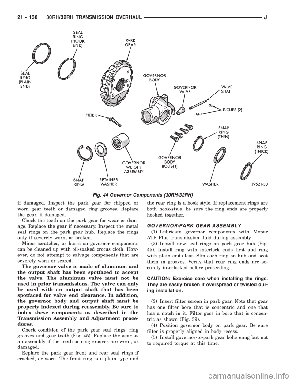
Check condition of the park gear seal rings, ring
grooves and gear teeth (Fig. 45). Replace the gear as
an assembly if the teeth or ring grooves are worn, or
damaged.
Replace the park gear front and rear seal rings if
cracked, or worn. The front ring is a plain type andthe rear ring is a hook style. If replacement rings are
both hook-style, be sure the ring ends are properly
hooked together.
GOVERNOR/PARK GEAR ASSEMBLY
(1) Lubricate governor components with Mopar
ATF Plus transmission fluid during assembly.
(2) Install new seal rings on park gear hub (Fig.
45). Install ring with interlock ends first and ring
with plain ends last. Slip each ring on hub and seat
them in grooves. Verify that rear ring ends are se-
curely interlocked before proceeding.
CAUTION: Exercise care when installing the rings.
They are easily broken if overspread or twisted dur-
ing installation.
(3) Insert filter screen in park gear. Note that gear
has one filter bore that is concentric and one that
has a notch in it. Filter goes in bore that is concen-
tric as shown (Fig. 39).
(4) Position governor body on park gear. Be sure
filter is properly aligned in body recess.
(5) Install governor-to-park gear bolts snug but not
to required torque at this time.
Fig. 44 Governor Components (30RH/32RH)
21 - 130 30RH/32RH TRANSMISSION OVERHAULJ