1995 JEEP YJ Rear End Gear Oil
[x] Cancel search: Rear End Gear OilPage 41 of 2158

DRIVETRAIN
INDEX
page page
Automatic Transmission.................... 23
Clutch and Brake Pedal Bushings............. 22
Clutch Master Cylinder..................... 22
Drive Shafts............................. 26Front and Rear Axles...................... 24
Manual Transmission...................... 22
Rubber and Plastic Hoses/Tubing............. 26
Transfer Case (4WD Vehicles)................ 24
CLUTCH AND BRAKE PEDAL BUSHINGS
If the clutch and brake pedal mechanism squeaks,
the pivot bushings should be lubricated. Use Mopar
Multi-Purpose Lubricant, or an equivalent. Refer to
Group 5, Brakes for location of bushings.
CLUTCH MASTER CYLINDER
LEVEL INSPECTION
WARNING: DO NOT ALLOW PETROLEUM OR WA-
TER BASE LIQUIDS TO CONTAMINATE CLUTCH
FLUID, SEAL DAMAGE AND CLUTCH FAILURE CAN
RESULT.
The clutch reservoir level should be inspected when
other underhood service is performed. (Fig. 1)
The fluid level is determined by its height in rela-
tion to the level indicator ring (Fig. 2) located inside
the reservoir. Add fluid until the height is level with
the indicator ring.
FLUID SPECIFICATION
Use Mopar, Brake And Hydraulic Clutch Fluid or
equivalent. Use only brake fluid conforming to DOT
3, Federal, Department of Transportation specifica-
tion. To avoid fluid contamination, use fluid from a
properly sealed container.CAUTION: Never use reclaimed brake fluid or fluid
from an unsealed container. In addition, do not use
fluid from a container that has been opened and al-
lowed to stand for an extended length of time.
Moisture in the air can be absorbed by the fluid,
which causes dilution with loss of effectiveness.
MANUAL TRANSMISSION
The manual transmission should be inspected for
oil leaks and proper oil level when other under vehi-
cle service is performed.
LUBRICANT SPECIFICATION
When it becomes necessary to add to or change the
lube oil in a Jeep manual transmission, use SAE
75W-90, API Quality Grade GL-5 gear lubricant.
LUBRICANT LEVEL
The fill-hole plug for all manual transmissions is
located on the right side of the case (Fig. 3). Deter-
mine the lubricant level according to the following
procedure.
(1) Remove the fill-hole plug (Fig. 3) from the
transmission. The lube oil should be level with the
bottom edge of the fill hole. The level can be slightly
below the bottom edge of the fill hole if the lube oil is
cold.
Fig. 1 Clutch Reservoir LocationÐTypical
Fig. 2 Hydraulic Clutch Fluid LevelÐTypical
0 - 22 LUBRICATION AND MAINTENANCEJ
Page 91 of 2158
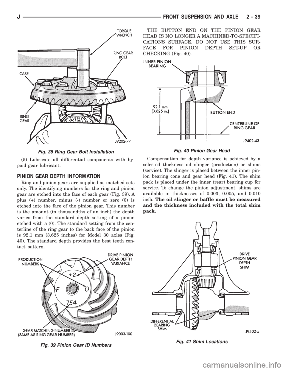
(5) Lubricate all differential components with hy-
poid gear lubricant.
PINION GEAR DEPTH INFORMATION
Ring and pinion gears are supplied as matched sets
only. The identifying numbers for the ring and pinion
gear are etched into the face of each gear (Fig. 39). A
plus (+) number, minus (-) number or zero (0) is
etched into the face of the pinion gear. This number
is the amount (in thousandths of an inch) the depth
varies from the standard depth setting of a pinion
etched with a (0). The standard setting from the cen-
terline of the ring gear to the back face of the pinion
is 92.1 mm (3.625 inches) for Model 30 axles (Fig.
40). The standard depth provides the best teeth con-
tact pattern.THE BUTTON END ON THE PINION GEAR
HEAD IS NO LONGER A MACHINED-TO-SPECIFI-
CATIONS SURFACE. DO NOT USE THIS SUR-
FACE FOR PINION DEPTH SET-UP OR
CHECKING (Fig. 40).
Compensation for depth variance is achieved by a
selected thickness oil slinger (production) or shims
(service). The slinger is placed between the inner pin-
ion bearing cone and gear head (Fig. 41). The shim
pack is placed under the inner (rear) bearing cup for
service. To change the pinion adjustment, shims are
available in thicknesses of 0.003, 0.005, and 0.010
inch.The oil slinger or baffle must be measured
and the thickness included with the total shim
pack.
Fig. 38 Ring Gear Bolt Installation
Fig. 39 Pinion Gear ID Numbers
Fig. 40 Pinion Gear Head
Fig. 41 Shim Locations
JFRONT SUSPENSION AND AXLE 2 - 39
Page 94 of 2158
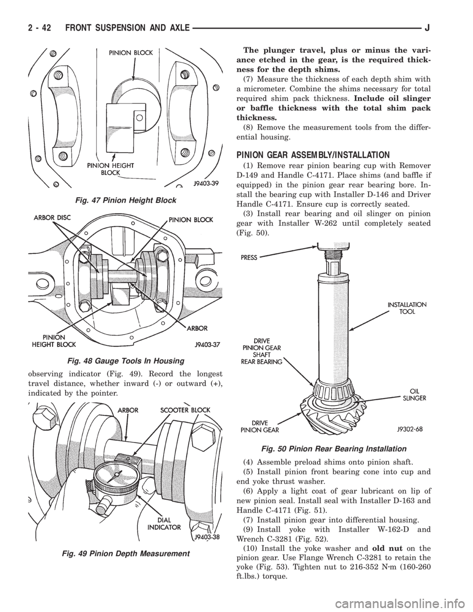
observing indicator (Fig. 49). Record the longest
travel distance, whether inward (-) or outward (+),
indicated by the pointer.The plunger travel, plus or minus the vari-
ance etched in the gear, is the required thick-
ness for the depth shims.
(7) Measure the thickness of each depth shim with
a micrometer. Combine the shims necessary for total
required shim pack thickness.Include oil slinger
or baffle thickness with the total shim pack
thickness.
(8) Remove the measurement tools from the differ-
ential housing.
PINION GEAR ASSEMBLY/INSTALLATION
(1) Remove rear pinion bearing cup with Remover
D-149 and Handle C-4171. Place shims (and baffle if
equipped) in the pinion gear rear bearing bore. In-
stall the bearing cup with Installer D-146 and Driver
Handle C-4171. Ensure cup is correctly seated.
(3) Install rear bearing and oil slinger on pinion
gear with Installer W-262 until completely seated
(Fig. 50).
(4) Assemble preload shims onto pinion shaft.
(5) Install pinion front bearing cone into cup and
end yoke thrust washer.
(6) Apply a light coat of gear lubricant on lip of
new pinion seal. Install seal with Installer D-163 and
Handle C-4171 (Fig. 51).
(7) Install pinion gear into differential housing.
(9) Install yoke with Installer W-162-D and
Wrench C-3281 (Fig. 52).
(10) Install the yoke washer andold nuton the
pinion gear. Use Flange Wrench C-3281 to retain the
yoke (Fig. 53). Tighten nut to 216-352 Nzm (160-260
ft.lbs.) torque.
Fig. 47 Pinion Height Block
Fig. 48 Gauge Tools In Housing
Fig. 49 Pinion Depth Measurement
Fig. 50 Pinion Rear Bearing Installation
2 - 42 FRONT SUSPENSION AND AXLEJ
Page 114 of 2158

MODEL 35 AXLE
INDEX
page page
Axle Shaft............................... 16
Axle Shaft Seal and Bearing................. 17
Backlash and Contact Pattern Analysis......... 27
Cleaning/Inspection........................ 20
Differential Assembly....................... 21
Differential Disassembly.................... 18
Differential Measurement and Installation........ 25
Differential Removal....................... 18
Drive Axle Assembly ReplacementÐXJ Vehicles . . 14Drive Axle Assembly ReplacementÐYJ Vehicles . . 14
Final Assembly........................... 29
General Information....................... 13
Lubricant Change......................... 13
Lubricant Specifications..................... 13
Pinion Gear Depth Information............... 21
Pinion Measurement and Assembly............ 22
Pinion Removal/Disassembly................. 19
Pinion Shaft Seal Replacement............... 15
GENERAL INFORMATION
The Model 35 housing has an iron center casting
(differential housing) with axle shaft tubes extending
from either side. The tubes are pressed into and
welded to the differential housing to form a one-piece
axle housing.
The integral type housing, hypoid gear design has
the centerline of the pinion set below the centerline
of the ring gear.
The axle has a vent hose to relieve internal pres-
sure caused by lubricant vaporization and internal
expansion.
The axles are equipped with semi-floating axle
shafts, meaning that loads are supported by the axle
shaft and bearings. The axle shafts are retained by
C-clips in the differential side gears.
The cover provides a means for servicing the differ-
ential without removing the axle.
Axles may be equipped with drum or disc brakes.
The axles that are equipped with ABS brake have a
tone ring pressed on the axle shaft. Use care when
removing axle shafts as NOT to damage the tone
wheel or the sensor.
The Model 35 axle has the assembly part number
and gear ratio listed on a tag. The tag is attached to
the housing cover. Build date identification codes are
stamped on the axle shaft tube cover side.
The differential case is a one-piece design. The dif-
ferential pinion mate shaft is retained with a
threaded roll pin. Differential bearing preload and
ring gear backlash is adjusted by the use of spacer
shims. Pinion bearing preload is set and maintained
by the use of a collapsible spacer.
For complete drive axle assembly removal
and installation refer to Drive Axle Assembly
Replacement in this Group.
LUBRICANT SPECIFICATIONS
Multi-purpose, hypoid gear lubricant should be
used for Model 35 axle. The lubricant should haveMIL-L-2105C and API GL 5 quality specifications.
MOPAR Hypoid Gear Lubricant conforms to both of
these specifications.
²Lubricant for Model 35 axle is a thermally stable
SAE 80W-90 gear lubricant.
²Lubricant for Model 35 axle with Trailer Tow is
SAE 75W-140 SYNTHETIC gear lubricant.
²Trac-Lok differentials add 4 oz. of friction modifier.
²Lubricant quantity is 1.66 L (3.50 pts.).
Refer to Group 0, Lubrication and Maintenance for
additional information.
CAUTION: If axle is submerged in water, lubricant
must be replaced immediately to avoid possible
premature axle failure.
LUBRICANT CHANGE
The gear lubricant will drain quicker if the vehicle
has been recently driven.
(1) Raise and support the vehicle.
(2) Remove the lubricant fill hole plug from the dif-
ferential housing cover.
(3) Remove the differential housing cover and
drain the lubricant from the housing.
(4) Clean the housing cavity with a flushing oil,
light engine oil or lint free cloth.Do not use water,
steam, kerosene or gasoline for cleaning.
(5) Remove the sealant from the housing and cover
surfaces.
(6) Apply a bead of MOPARtSilicone Rubber Seal-
ant to the housing cover (Fig. 1).Allow the sealant
to cure for a few minutes.
Install the housing cover within 5 minutes af-
ter applying the sealant. If not installed the
sealant must be removed and another bead ap-
plied.
(7) Install the cover and any identification tag.
Tighten the cover bolts to 41 Nzm (30 ft. lbs.) torque.
(8) Refill differential with Mopar Hypoid Gear Lu-
bricant to bottom of the fill plug hole.
JREAR SUSPENSION AND AXLES 3 - 13
Page 225 of 2158

CLUTCH DIAGNOSIS
INDEX
page page
Clutch Contamination....................... 3
Clutch Cover and Disc Runout................ 3
Clutch Housing Misalignment................. 4
Clutch Misalignment........................ 3Flywheel Runout........................... 3
General Diagnosis Information................ 3
Inspection and Diagnosis Charts............... 4
Installation Methods and Parts Usage........... 4
GENERAL DIAGNOSIS INFORMATION
Unless the cause of a clutch problem is obvious, ac-
curate problem diagnosis will usually require a road
test to confirm a problem. Component inspection will
then be required to determine the actual problem
cause.
During a road test, drive the vehicle at normal
speeds. Shift the transmission through all gear
ranges and observe clutch action. If chatter, grab,
slip, or improper release is experienced, remove and
inspect the clutch components. However, if the prob-
lem is noise or hard shifting, further diagnosis may
be needed as the transmission or another driveline
component may be at fault. Careful observation dur-
ing the test will help narrow the problem area.
CLUTCH CONTAMINATION
Fluid contamination is a frequent cause of clutch
malfunctions. Oil, water, or clutch fluid on the clutch
disc and pressure plate surfaces will cause chatter,
slip and grab.
During inspection, note if any components are con-
taminated with oil, hydraulic fluid, or water/road
splash.
Oil contamination indicates a leak at either the
rear main seal or transmission input shaft. Oil leak-
age produces a residue of oil on the housing interior
and on the clutch cover and flywheel. Heat buildup
caused by slippage between the cover, disc and fly-
wheel, can sometimes bake the oil residue onto the
components. The glaze-like residue ranges in color
from amber to black.
Road splash contamination means dirt/water is en-
tering the clutch housing due to loose bolts, housing
cracks, or through hydraulic line openings. Driving
through deep water puddles can force water/road
splash into the housing through such openings.
Clutch fluid leaks are usually from damaged slave
cylinder push rod seals. This type of leak can only be
confirmed by visual inspection.
CLUTCH MISALIGNMENT
Clutch components must be in proper alignment
with the crankshaft and transmission input shaft.Misalignment caused by excessive runout or warpage
of any clutch component will cause grab, chatter and
improper clutch release.
FLYWHEEL RUNOUT
Check flywheel runout whenever misalignment is
suspected. Flywheel runout should not exceed 0.08
mm (0.003 in.). Measure runout at the outer edge of
the flywheel face with a dial indicator. Mount the in-
dicator on a stud installed in place of one of the fly-
wheel bolts.
Common causes of runout are:
²heat warpage
²improper machining
²incorrect bolt tightening
²improper seating on crankshaft flange shoulder
²foreign material on crankshaft flange
Flywheel machining is not recommended. The fly-
wheel clutch surface is machined to a unique contour
and machining will negate this feature. However, mi-
nor flywheel scoring can be cleaned up by hand with
180 grit emery, or with surface grinding equipment.
Remove only enough material to reduce scoring (ap-
proximately 0.001 - 0.003 in.). Heavy stock removal
isnot recommended.Replace the flywheel if scor-
ing is severe and deeper than 0.076 mm (0.003 in.).
Excessive stock removal can result in flywheel crack-
ing or warpage after installation; it can also weaken
the flywheel and interfere with proper clutch release.
Clean the crankshaft flange before mounting the
flywheel. Dirt and grease on the flange surface may
cock the flywheel causing excessive runout. Use new
bolts when remounting a flywheel and secure the
bolts with Mopar Lock And Seal. Tighten flywheel
bolts to specified torque only. Overtightening can dis-
tort the flywheel hub causing runout.
CLUTCH COVER AND DISC RUNOUT
Check the clutch disc before installation. Axial
(face) runout of anewdisc should not exceed 0.50
mm (0.020 in.). Measure runout about 6 mm (1/4 in.)
from the outer edge of the disc facing. Obtain an-
other disc if runout is excessive.
Check condition of the clutch before installation. A
warped cover or diaphragm spring will cause grab
and incomplete release or engagement. Be careful
JCLUTCH DIAGNOSIS 6 - 3
Page 360 of 2158

HEADLAMP HIGH BEAM INDICATOR LAMP
The high beam indicator lamp is controlled by the
headlamp dimmer (multi-function) switch. One side
of the indicator bulb is grounded at all times. The
other side of the bulb receives battery feed through
the contacts of the dimmer switch when the multi-
function switch stalk is actuated to turn the head-
lamp high beams on. Refer to Group 8L - Lamps for
more information.
LOW FUEL WARNING LAMP
A Light-Emitting Diode (LED) on the face of the
fuel gauge will light when the fuel level falls below
approximately 4 gallons. A low fuel warning module
attached to the rear of the fuel gauge controls when
the LED will light. When the module senses 66.5
ohms or more resistance from the fuel level sending
unit for 10 continuous seconds, the LED will light.
When the module senses 63.5 ohms or less resistance
from the fuel level sending unit for 20 continuous
seconds, the LED is turned off.
LOW OIL PRESSURE WARNING LAMP
The low oil pressure warning lamp lights with the
ignition switch in the ON position and the engine not
running. The lamp should be off when the engine is
running. Battery voltage is supplied to one side of
the indicator bulb when the ignition switch is turned
ON. The warning lamp side of the combination oil
pressure sending unit is connected to the other side
of the bulb. When normal engine oil pressure is ap-
plied to the sending unit, resistance on the warning
lamp side is high and the lamp goes off. When engine
oil pressure is too low, resistance on the warning
lamp side of the sending unit is low, which causes
the bulb to light.
LOW WASHER FLUID WARNING LAMP
The low washer fluid warning lamp indicates when
the fluid level in the washer reservoir is too low. The
washer fluid level sensor uses a float in the reservoir
to monitor fluid level. The action of the float opens or
closes the switch within the sensor that provides ig-
nition-switched battery voltage to the lamp bulb. Re-
fer to Group 8K - Wiper and Washer Systems for
more information.
MALFUNCTION INDICATOR LAMP
The CHECK ENGINE or Malfunction Indicator
Lamp (MIL) lights each time the ignition switch is
turned ON, and stays on for 3 seconds as a bulb test.
If the Powertrain Control Module (PCM) receives an
incorrect signal or no signal from certain fuel oremission system related circuits or components, the
lamp is turned on. This will indicate that the PCM
has recorded a Diagnostic Trouble Code (DTC) in
electronic memory for a circuit or component mal-
function. Refer to Group 14 - Fuel System for more
information.
SEAT BELT REMINDER LAMP
The seat belt reminder lamp lights for 4 to 8 sec-
onds after the ignition switch is turned to the ON po-
sition. A timer in the chime/buzzer module controls
ignition-switched battery feed to the lamp. Refer to
Group 8U - Chime/Buzzer Warning Systems for more
information.
TURN SIGNAL INDICATOR LAMPS
The left and right turn signal indicator lamps are
controlled by the turn signal and hazard warning
(multi-function) switches. One side of the bulb for
each lamp is grounded at all times. The other side of
the bulb receives battery feed through the contacts of
the multi-function switch when the turn signal lever
(multi-function switch stalk) or hazard warning but-
ton are actuated. Refer to Group 8J - Turn Signal
and Hazard Warning Systems for more information.
UPSHIFT INDICATOR LAMP
Vehicles equipped with manual transmissions have
an optional upshift indicator lamp. Ground feed for
the lamp is switched by the Powertrain Control Mod-
ule (PCM). The lamp lights to indicate when the
driver should shift to the next highest gear for best
fuel economy. The PCM will turn the lamp off after 3
to 5 seconds if the upshift is not performed. The lamp
will remain off until the vehicle stops accelerating
and is brought back to the range of lamp operation,
or until the transmission is shifted into another gear.
The indicator lamp is normally on when the igni-
tion switch is turned ON and is turned off when the
engine is started. The lamp will be turned on during
vehicle operation according to engine speed and load.
CLUSTER ILLUMINATION LAMPS
All cluster illumination lamps receive battery feed
from the instrument lamps fuse in the fuseblock
module through the panel dimmer rheostat of the
headlamp switch. When the park or headlamps are
on, the cluster illumination lamps light. Illumination
brightness can be adjusted by rotating the headlamp
switch knob (clockwise to dim, counterclockwise to
brighten).
8E - 4 INSTRUMENT PANEL AND GAUGESÐXJJ
Page 1316 of 2158
LUBRICATION SYSTEM
A gearÐtype positive displacement pump is
mounted at the underside of the block opposite the
No. 4 main bearing. The pump draws oil through the
screen and inlet tube from the sump at the rear of
the oil pan. The oil is driven between the drive and
idler gears and pump body, then forced through the
outlet to the block. An oil gallery in the block chan-
nels the oil to the inlet side of the full flow oil filter.
After passing through the filter element, the oil
passes from the center outlet of the filter through an
oil gallery that channels the oil up to the main gal-
lery which extends the entire length of the block.
Galleries extend downward from the main oil gal-
lery to the upper shell of each main bearing. The
crankshaft is drilled internally to pass oil from the
main bearing journals (except number 4 main bear-
ing journal) to the connecting rod journals. Each con-
necting rod bearing cap has a small squirt hole, oilpasses through the squirt hole and is thrown off as
the rod rotates. This oil throwoff lubricates the cam-
shaft lobes, distributor drive gear, cylinder walls, and
piston pins.
The hydraulic valve tappets receive oil directly
from the main oil gallery. Oil is provided to the cam-
shaft bearing through galleries. The front camshaft
bearing journal passes oil through the camshaft
sprocket to the timing chain. Oil drains back to the
oil pan under the number one main bearing cap.
The oil supply for the rocker arms and bridged
pivot assemblies is provided by the hydraulic valve
tappets which pass oil through hollow push rods to a
hole in the corresponding rocker arm. Oil from the
rocker arm lubricates the valve train components,
then passes down through the push rod guide holes
in the cylinder head past the valve tappet area, and
returns to the oil pan.
J2.5L ENGINE 9 - 37
Page 1358 of 2158
LUBRICATION SYSTEM
A gearÐtype positive displacement pump is
mounted at the underside of the block opposite the
No. 4 main bearing. The pump draws oil through the
screen and inlet tube from the sump at the rear of
the oil pan. The oil is driven between the drive and
idler gears and pump body, then forced through the
outlet to the block. An oil gallery in the block chan-
nels the oil to the inlet side of the full flow oil filter.
After passing through the filter element, the oil
passes from the center outlet of the filter through an
oil gallery that channels the oil up to the main gal-
lery which extends the entire length of the block.
Galleries extend downward from the main oil gal-
lery to the upper shell of each main bearing. The
crankshaft is drilled internally to pass oil from the
main bearing journals (except number 4 main bear-
ing journal) to the connecting rod journals. Each con-
necting rod bearing cap has a small squirt hole, oilpasses through the squirt hole and is thrown off as
the rod rotates. This oil throwoff lubricates the cam-
shaft lobes, distributor drive gear, cylinder walls, and
piston pins.
The hydraulic valve tappets receive oil directly
from the main oil gallery. Oil is provided to the cam-
shaft bearing through galleries. The front camshaft
bearing journal passes oil through the camshaft
sprocket to the timing chain. Oil drains back to the
oil pan under the number one main bearing cap.
The oil supply for the rocker arms and bridged
pivot assemblies is provided by the hydraulic valve
tappets which pass oil through hollow push rods to a
hole in the corresponding rocker arm. Oil from the
rocker arm lubricates the valve train components,
then passes down through the push rod guide holes
in the cylinder head past the valve tappet area, and
returns to the oil pan.
J4.0L ENGINE 9 - 79