1995 JEEP YJ battery
[x] Cancel search: batteryPage 439 of 2158
gate wiper switch terminal C. Meter should read
battery voltage. If not OK, replace switch.
(4) Remove liftgate cover and measure resistance
from liftgate wiper motor terminal 1 to a good
ground. Meter should read zero ohms. If not OK, re-
pair open to ground splice.
(5) Turn ignition switch to ACCESSORY and lift-
gate wiper switch to WASH. Measure voltage at mo-
tor connector terminals 2, 3 and 4. Meter should read
battery voltage. If OK, replace wiper motor. If not
OK, repair open(s) to liftgate wiper switch.
LIFTGATE WASHER SYSTEM
(1) Turn ignition switch to ACCESSORY and place
liftgate wiper/washer switch in WASH. Operate lift-
gate wiper motor. If motor does not operate check
fuse 1. Replace faulty fuse, if required.
(2) Turn ignition switch to ACCESSORY and un-
plug liftgate washer pump connector.
(a) Measure resistance at pump connector termi-
nal B (ignition switch OFF). Meter should read
zero ohms. If not OK, repair open to ground.
(b) Measure voltage at pump connector terminal
A, switch in WASH. Meter should read battery
voltage. If OK, replace pump. If not OK, go to step
3.
(3) Remove switch and reconnect below instrument
panel. Backprobe switch connector with ignition
switch in ACCESSORY.
(a) Measure voltage at switch connector terminal
B. Meter should read battery voltage. If not OK, re-
pair open to fuse.
(b) Measure voltage at switch connector terminal
A, switch in WASH. Meter should read battery
voltage. If not OK, replace switch.
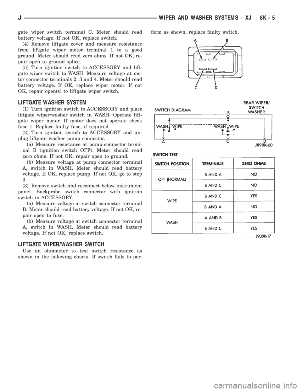
LIFTGATE WIPER/WASHER SWITCH
Use an ohmmeter to test switch resistance as
shown in the following charts. If switch fails to per-form as shown, replace faulty switch.
JWIPER AND WASHER SYSTEMS - XJ 8K - 5
Page 441 of 2158
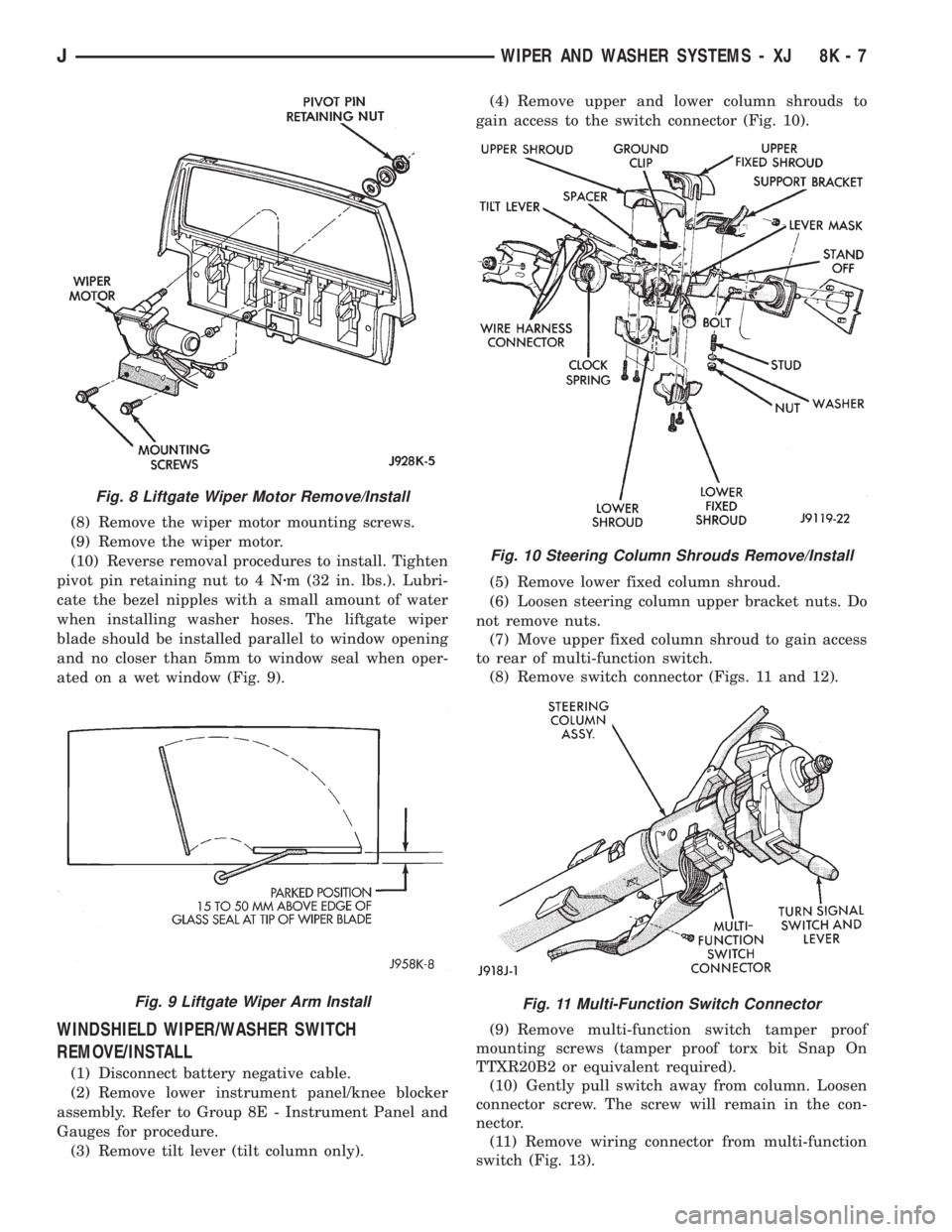
(8) Remove the wiper motor mounting screws.
(9) Remove the wiper motor.
(10) Reverse removal procedures to install. Tighten
pivot pin retaining nut to 4 Nzm (32 in. lbs.). Lubri-
cate the bezel nipples with a small amount of water
when installing washer hoses. The liftgate wiper
blade should be installed parallel to window opening
and no closer than 5mm to window seal when oper-
ated on a wet window (Fig. 9).
WINDSHIELD WIPER/WASHER SWITCH
REMOVE/INSTALL
(1) Disconnect battery negative cable.
(2) Remove lower instrument panel/knee blocker
assembly. Refer to Group 8E - Instrument Panel and
Gauges for procedure.
(3) Remove tilt lever (tilt column only).(4) Remove upper and lower column shrouds to
gain access to the switch connector (Fig. 10).
(5) Remove lower fixed column shroud.
(6) Loosen steering column upper bracket nuts. Do
not remove nuts.
(7) Move upper fixed column shroud to gain access
to rear of multi-function switch.
(8) Remove switch connector (Figs. 11 and 12).
(9) Remove multi-function switch tamper proof
mounting screws (tamper proof torx bit Snap On
TTXR20B2 or equivalent required).
(10) Gently pull switch away from column. Loosen
connector screw. The screw will remain in the con-
nector.
(11) Remove wiring connector from multi-function
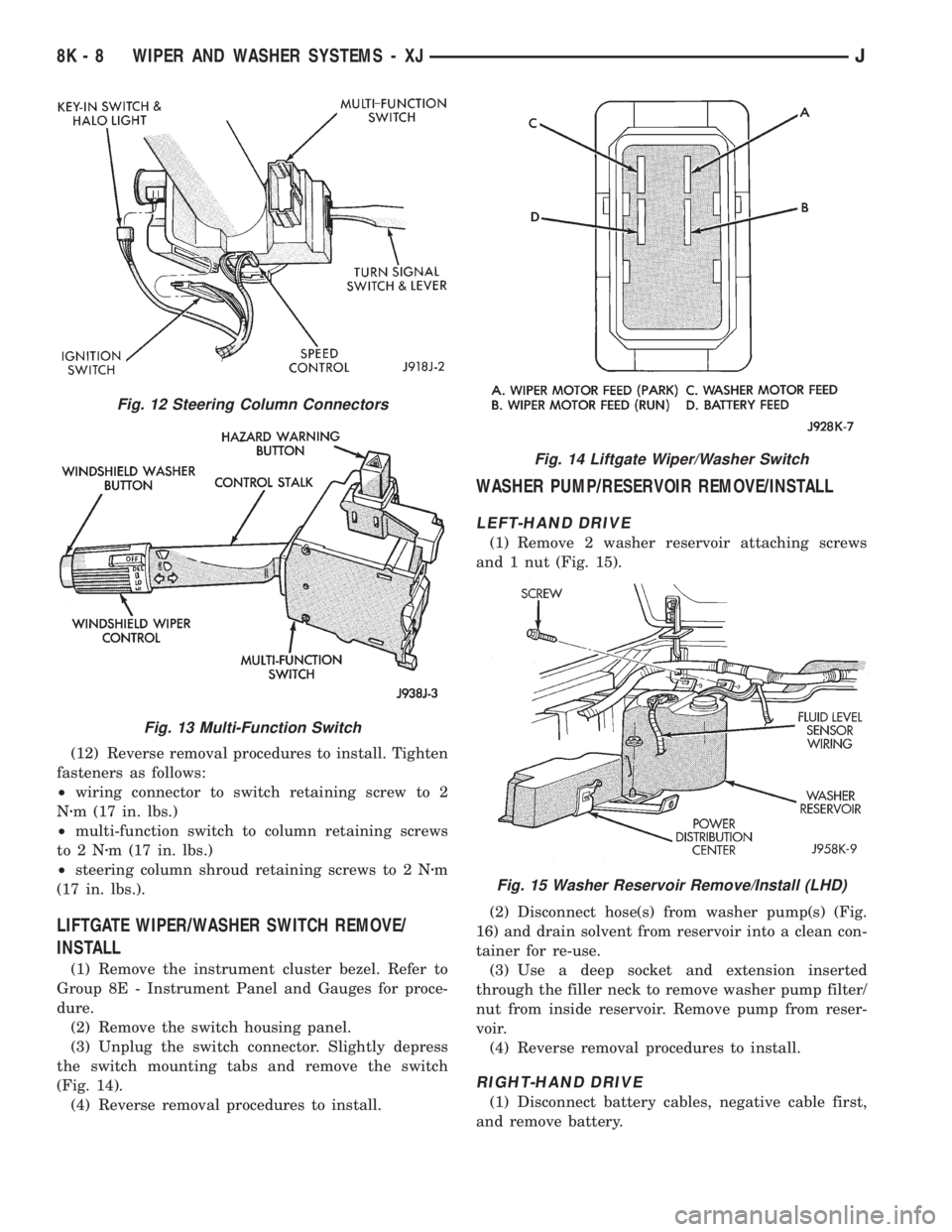
switch (Fig. 13).
Fig. 8 Liftgate Wiper Motor Remove/Install
Fig. 9 Liftgate Wiper Arm Install
Fig. 10 Steering Column Shrouds Remove/Install
Fig. 11 Multi-Function Switch Connector
JWIPER AND WASHER SYSTEMS - XJ 8K - 7
Page 442 of 2158
(12) Reverse removal procedures to install. Tighten
fasteners as follows:
²wiring connector to switch retaining screw to 2
Nzm (17 in. lbs.)
²multi-function switch to column retaining screws
to2Nzm (17 in. lbs.)
²steering column shroud retaining screws to 2 Nzm
(17 in. lbs.).
LIFTGATE WIPER/WASHER SWITCH REMOVE/
INSTALL
(1) Remove the instrument cluster bezel. Refer to
Group 8E - Instrument Panel and Gauges for proce-
dure.
(2) Remove the switch housing panel.
(3) Unplug the switch connector. Slightly depress
the switch mounting tabs and remove the switch
(Fig. 14).
(4) Reverse removal procedures to install.
WASHER PUMP/RESERVOIR REMOVE/INSTALL
LEFT-HAND DRIVE
(1) Remove 2 washer reservoir attaching screws
and 1 nut (Fig. 15).
(2) Disconnect hose(s) from washer pump(s) (Fig.
16) and drain solvent from reservoir into a clean con-
tainer for re-use.
(3) Use a deep socket and extension inserted
through the filler neck to remove washer pump filter/
nut from inside reservoir. Remove pump from reser-
voir.
(4) Reverse removal procedures to install.
RIGHT-HAND DRIVE
(1) Disconnect battery cables, negative cable first,
and remove battery.
Fig. 12 Steering Column Connectors
Fig. 13 Multi-Function Switch
Fig. 14 Liftgate Wiper/Washer Switch
Fig. 15 Washer Reservoir Remove/Install (LHD)
8K - 8 WIPER AND WASHER SYSTEMS - XJJ
Page 446 of 2158
DIAGNOSIS - YJ
WINDSHIELD WIPER SYSTEM
(1) Remove circuit breaker from fuseblock module
and turn ignition switch to ACCESSORY or ON.
(a) Measure voltage at battery side of circuit
breaker cavity. Meter should read battery voltage.
If not OK, repair wiring from ignition switch.
(b) Measure resistance across circuit breaker ter-
minals. Meter should read zero ohms. If not OK,
replace failed circuit breaker.
(2) Unplug wiper motor side of wiring harness con-
nector (gray) from wiper switch side of wiring har-
ness connector (black), or from intermittent wipe
module (if equipped) at base of steering column. Turn
ignition switch to ACCESSORY or ON.
(a) Measure voltage at unplugged wiper motor
side of wiring harness connector (gray) terminal D.
Meter should read battery voltage. If not OK, re-
pair wiring from circuit breaker.
(b) Turn ignition switch to OFF and measure re-
sistance from unplugged wiper motor side of wiring
harness connector (gray) terminal G to ground.
Meter should read zero ohms. If not OK, repair
wiring to ground.
(3) Leave ignition switch in OFF, and back probe
wiring harness connector at wiper motor. Measure re-
sistance from terminal E of wiper motor side of con-
nector to ground. Meter should read zero ohms. If not
OK, repair wiring to ground.
(4) If equipped with intermittent wipe, turn igni-
tion switch to ACCESSORY or ON. Turn wiper
switch to LOW or HIGH. Unplug wiper switch side of
wiring harness connector (black) from intermittent
wipe module. Then plug both connectors that have
been removed from intermittent wipe module into
each other.
CAUTION: DO NOT move the wiper switch to DE-
LAY with the intermittent wipe module removed
from the circuit. If the switch is moved to the DE-
LAY position during the next step, the switch will be
damaged.
Test wiper operation in LOW and HIGH speed
modes, and test washer operation. If these modes
were inoperative, but are OK now, replace failed in-
termittent wipe module.
(5) To test the wiper/washer switch, see Windshield
Wiper/Washer Switch Testing. Turn ignition switch to
OFF. Position the wiper switch as indicated, and
back probe wiper switch side of wiring harness con-
nector (black). If switch tests OK, go to step 6. If not
OK, replace switch and go to step 7.
(6) To further test the wiper/washer switch, turn
ignition switch to ACCESSORY or ON. Position thewiper switch as indicated in the tests below, and
back probe wiper switch side of wiring harness con-
nector (black).
(a) Measure voltage at connector terminal E with
wiper switch in LOW, MIST and with washer
switch depressed. Meter should read battery volt-
age. If not OK, replace switch.
(b) Measure voltage at connector terminal C with
wiper switch in HIGH. Meter should read battery
voltage. If not OK, replace switch.
(c) With wiper switch in LOW or HIGH, measure
voltage at connector terminal F, then move wiper
switch to OFF. Meter should read battery voltage
until wipers park and then zero volts. If OK, go to
step 7. If not OK, check wiring to wiper motor, then
go to step 8.
(7) To test the wiper motor, turn the ignition
switch to ACCESSORY or ON. Position the wiper
switch and back probe the motor connector as indi-
cated.
(a) Wiper switch in any position, measure volt-
age at terminal B. Meter should read battery volt-
age. If not OK, repair wiring from circuit breaker.
(b) Wiper switch in LOW, measure voltage at ter-
minal A. Meter should read battery voltage. If OK,
but wipers do not operate, replace failed wiper mo-
tor. If not OK, repair wiring from switch or inter-
mittent wipe module connector.
(c) Wiper switch in HIGH, measure voltage at
terminal H. Meter should read battery voltage. If
OK, but wipers do not operate, replace failed wiper
motor. If not OK, repair wiring from switch or in-
termittent wipe module connector.
(d) Wiper switch in LOW or HIGH, voltmeter
connected to terminal D. Turn wiper switch to OFF
and observe meter. Meter should read battery volt-
age when switch goes to OFF, then zero volts after
wipers park. If battery voltage is present, but wip-
ers fail to park; or, if no battery voltage present, re-
place failed wiper motor.
WINDSHIELD WASHER SYSTEM
WITH NON-INTERMITTENT WIPE
(1) Measure resistance from washer pump connec-
tor terminal B to a clean chassis ground. Meter
should read zero ohms. If not OK, repair open be-
tween terminal B and ground.
(2) Turn ignition switch to ON and press washer
switch.
(a) Measure voltage at switch connector terminal
B. Meter should read battery voltage. If not OK, re-
place wiper/washer switch.
(b) Measure voltage at washer pump connector
terminal A. Meter should read battery voltage. If
8K - 12 WIPER AND WASHER SYSTEMS - YJJ
Page 447 of 2158
OK, replace pump. If not OK, repair open between
switch connector and pump connector.
WITH INTERMITTENT WIPE
(1) Measure resistance from washer pump connec-
tor terminal B to a clean chassis ground. Meter
should read zero ohms. If not OK, repair open be-
tween terminal B and ground.
(2) Turn ignition switch to ON and rotate washer
switch tab forward.
(a) Measure voltage at wiper/washer switch con-
nector terminal B located at intermittent wipe
module. Meter should read battery voltage. If not
OK, replace wiper switch.(b) Measure voltage at intermittent wipe module
connector terminal B (to washer pump). Meter
should read battery voltage. If not OK, replace in-
termittent wipe module.
(c) Measure voltage at washer pump connector
terminal A. Meter should read battery voltage. If
OK, replace pump. If not OK, repair open from in-
termittent wipe module connector terminal B.
WINDSHIELD WIPER/WASHER SWITCH
To test windshield wiper/washer switches, perform
the resistance tests shown in the following charts. If
switch fails any test, replace faulty switch.
JWIPER AND WASHER SYSTEMS - YJ 8K - 13
Page 450 of 2158

LIFTGATE WIPER/WASHER SYSTEM
(1) Turn ignition switch to ON and liftgate wiper/
washer switch to WASH.
(a) Measure voltage at switch connector terminal
P. Meter should read battery voltage. If not OK,
check fuse 1.
(b) Measure voltage at switch connector terminal
B. Meter should read battery voltage. If not OK, re-
place switch.
(c) Measure voltage at switch connector terminal
A. Meter should read battery voltage. If not OK, re-
place switch.
(2) Unplug liftgate washer pump connector.
(a) With ignition switch in OFF position, mea-
sure resistance at pump connector black wire to
ground. Meter should read zero ohms. If not OK,
repair open to ground.
(b) With ignition switch in ON position, measure
voltage at pump connector brown/white wire,
switch in WASH. Meter should read battery volt-
age. If OK, replace pump. If not OK, check wiring.
(3) Turn ignition switch to ON, unplug liftgate
wiper motor connector and place wiper switch in
WIPE.
(a) Measure resistance at motor connector termi-
nal B to ground. Meter should read zero ohms. If
not OK, repair open to ground.
(b) Measure voltage at motor connector terminal
A. Meter should read battery voltage. If not OK,
check wiring to fuse.
(c) Measure voltage at motor connector terminal
C. Meter should read battery voltage. If OK, re-
place motor. If not OK, repair open to switch.
LIFTGATE WIPER/WASHER SWITCH
See Liftgate Wiper/Washer Switch Diagram (Fig. 1)
and Liftgate Wiper Switch Tests (Fig. 2). Check
switch continuity and resistance accordingly. If
switch fails any test, replace faulty switch.
Fig. 1 Liftgate Wiper/Washer Switch Diagram
Fig. 2 Liftgate Wiper/Washer Switch Tests
8K - 16 WIPER AND WASHER SYSTEMS - YJJ
Page 454 of 2158
LIFTGATE WIPER MOTOR REMOVE/INSTALL
(1) Remove wiper arm from motor (see Liftgate
Wiper Arm Remove/Install).
(2) Remove pivot shaft retaining nut.
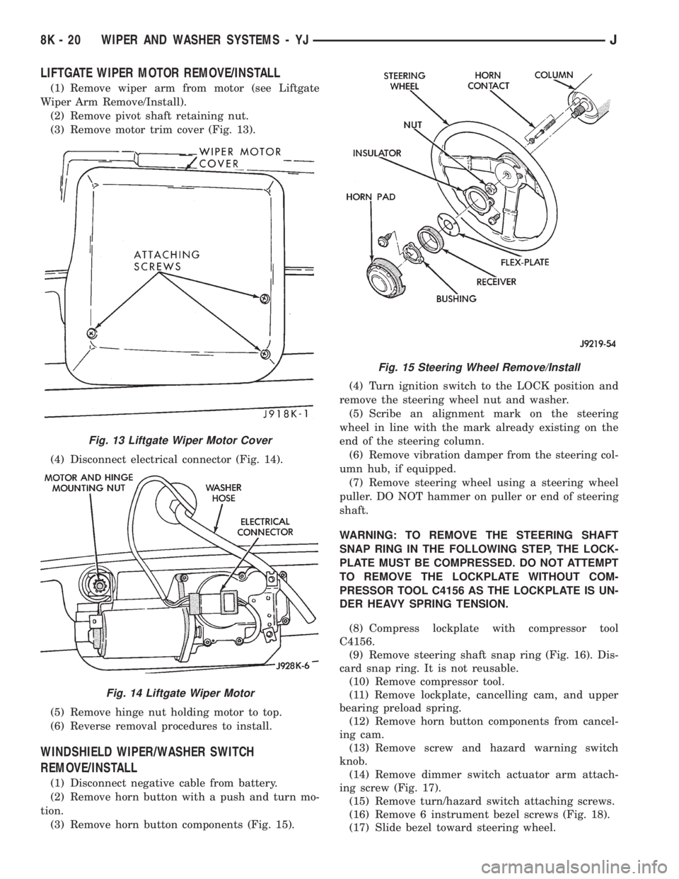
(3) Remove motor trim cover (Fig. 13).
(4) Disconnect electrical connector (Fig. 14).
(5) Remove hinge nut holding motor to top.
(6) Reverse removal procedures to install.
WINDSHIELD WIPER/WASHER SWITCH
REMOVE/INSTALL
(1) Disconnect negative cable from battery.
(2) Remove horn button with a push and turn mo-
tion.
(3) Remove horn button components (Fig. 15).(4) Turn ignition switch to the LOCK position and
remove the steering wheel nut and washer.
(5) Scribe an alignment mark on the steering
wheel in line with the mark already existing on the
end of the steering column.
(6) Remove vibration damper from the steering col-
umn hub, if equipped.
(7) Remove steering wheel using a steering wheel
puller. DO NOT hammer on puller or end of steering
shaft.
WARNING: TO REMOVE THE STEERING SHAFT
SNAP RING IN THE FOLLOWING STEP, THE LOCK-
PLATE MUST BE COMPRESSED. DO NOT ATTEMPT
TO REMOVE THE LOCKPLATE WITHOUT COM-
PRESSOR TOOL C4156 AS THE LOCKPLATE IS UN-
DER HEAVY SPRING TENSION.
(8) Compress lockplate with compressor tool
C4156.
(9) Remove steering shaft snap ring (Fig. 16). Dis-
card snap ring. It is not reusable.
(10) Remove compressor tool.
(11) Remove lockplate, cancelling cam, and upper
bearing preload spring.
(12) Remove horn button components from cancel-
ing cam.
(13) Remove screw and hazard warning switch
knob.
(14) Remove dimmer switch actuator arm attach-
ing screw (Fig. 17).
(15) Remove turn/hazard switch attaching screws.
(16) Remove 6 instrument bezel screws (Fig. 18).
(17) Slide bezel toward steering wheel.
Fig. 13 Liftgate Wiper Motor Cover
Fig. 14 Liftgate Wiper Motor
Fig. 15 Steering Wheel Remove/Install
8K - 20 WIPER AND WASHER SYSTEMS - YJJ
Page 461 of 2158

LAMPS
CONTENTS
page page
BULB APPLICATIONÐXJ VEHICLES......... 18
GENERAL INFORMATION.................. 1INTERIOR LAMPS....................... 16
SERVICE PROCEDURES................... 6
GENERAL INFORMATION
Each vehicle is equipped with various lamp assem-
blies. A good ground is necessary for proper lighting
operation. Grounding is provided by the lamp socket
when it comes in contact with the metal body, or
through a separate ground wire.
When changing lamp bulbs check the socket for
corrosion. If corrosion is present, clean it with a wire
brush and coat the inside of the socket lightly with
Mopar Multi-Purpose Grease or equivalent.
DIAGNOSTIC PROCEDURESÐXJ
When a vehicle experiences problems with the
headlamp system, verify the condition of the batteryconnections, charging system, headlamp bulbs, wire
connectors, relay, high beam dimmer switch and
headlamp switch. Refer to Group 8W, Wiring Dia-
grams for component locations and circuit informa-
tion.
Always begin any diagnosis by testing all of the
fuses and circuit breakers in the system. Refer to
Group 8W, Wiring Diagrams.
JLAMPS 8L - 1