1995 JEEP YJ battery
[x] Cancel search: batteryPage 423 of 2158

for pin 2 (Fig. 6). If OK, go to next step. If not OK,
see diagnosis for Stop Lamp Switch.
(4) Connect a jumper wire between servo harness
connector cavity for pin 2 and pin 2 of the servo.
Check for battery voltage at pins 1, 3 and 4 of the
servo. If OK, go to next step. If not OK, replace the
servo.
(5) Turn ignition switch to OFF position. Check for
continuity between servo harness connector cavity for
pin 1 and a good ground. There should be continuity.
If not OK, repair open circuit to ground as required.
POWERTRAIN CONTROL MODULE
(1) Disconnect 60-way connector from the PCM, lo-
cated on the dash panel near the wiper motor in the
engine compartment (Fig. 7).(2) Connect negative lead of voltmeter to a good
body ground near the module.
(3) For the following tests, the ignition switch
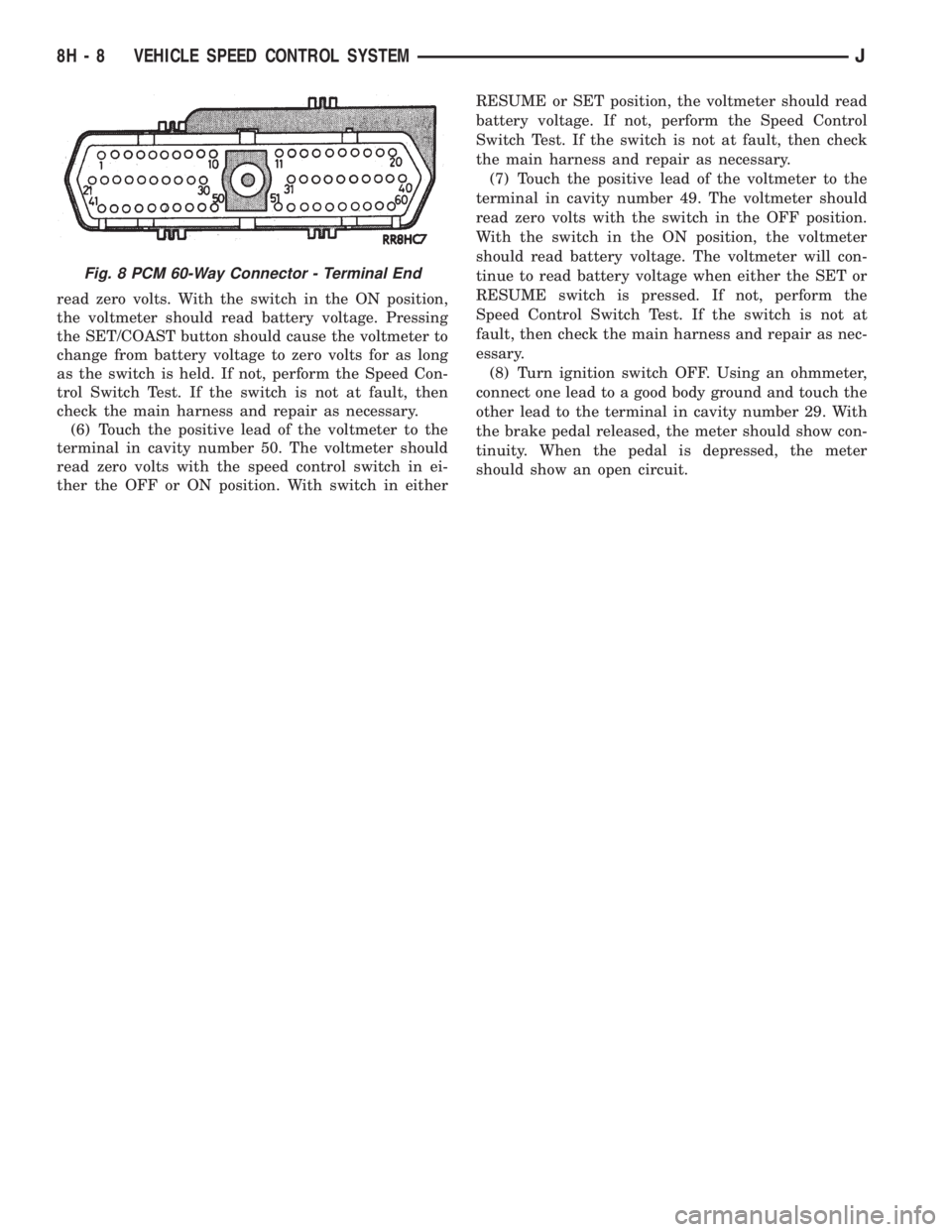
must be in the ON position. See Fig. 8 for controller
terminal locations. Touch the positive lead of the
voltmeter to the terminal in cavity number 33. With
the speed control switch in the OFF position, the
voltmeter should read zero volts. With the speed con-
trol switch in the ON position, the voltmeter should
read battery voltage. If not, repair the main harness
as necessary.
(4) Touch the positive lead of the voltmeter to the
terminal in cavity number 53. As in step (3), the volt-
meter should read zero volts with the switch in the
OFF position, and battery voltage with the switch in
the ON position.
(5) Touch the positive lead of the voltmeter to the
terminal in cavity number 48. With the speed control
switch in the OFF position, the voltmeter should
Fig. 4 Speed Control Servo - LHD
Fig. 5 Speed Control Servo - RHD
Fig. 6 Servo Harness Connector
Fig. 7 Powertrain Control Module
JVEHICLE SPEED CONTROL SYSTEM 8H - 7
Page 424 of 2158
read zero volts. With the switch in the ON position,
the voltmeter should read battery voltage. Pressing
the SET/COAST button should cause the voltmeter to
change from battery voltage to zero volts for as long
as the switch is held. If not, perform the Speed Con-
trol Switch Test. If the switch is not at fault, then
check the main harness and repair as necessary.
(6) Touch the positive lead of the voltmeter to the
terminal in cavity number 50. The voltmeter should
read zero volts with the speed control switch in ei-
ther the OFF or ON position. With switch in eitherRESUME or SET position, the voltmeter should read
battery voltage. If not, perform the Speed Control
Switch Test. If the switch is not at fault, then check
the main harness and repair as necessary.
(7) Touch the positive lead of the voltmeter to the
terminal in cavity number 49. The voltmeter should
read zero volts with the switch in the OFF position.
With the switch in the ON position, the voltmeter
should read battery voltage. The voltmeter will con-
tinue to read battery voltage when either the SET or
RESUME switch is pressed. If not, perform the
Speed Control Switch Test. If the switch is not at
fault, then check the main harness and repair as nec-
essary.
(8) Turn ignition switch OFF. Using an ohmmeter,
connect one lead to a good body ground and touch the
other lead to the terminal in cavity number 29. With
the brake pedal released, the meter should show con-
tinuity. When the pedal is depressed, the meter
should show an open circuit.
Fig. 8 PCM 60-Way Connector - Terminal End
8H - 8 VEHICLE SPEED CONTROL SYSTEMJ
Page 425 of 2158
SERVICE PROCEDURES
SPEED CONTROL SERVO REMOVE/INSTALL
(1) Disconnect battery negative cable.
(2) Disconnect vacuum hose at servo.
(3) Remove 2 nuts on servo cable sleeve.
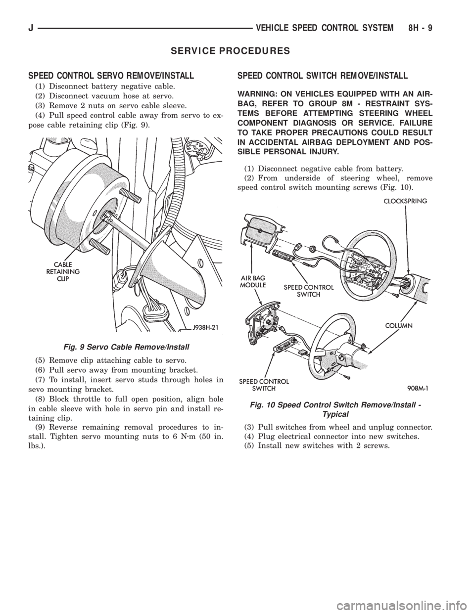
(4) Pull speed control cable away from servo to ex-
pose cable retaining clip (Fig. 9).
(5) Remove clip attaching cable to servo.
(6) Pull servo away from mounting bracket.
(7) To install, insert servo studs through holes in
sevo mounting bracket.
(8) Block throttle to full open position, align hole
in cable sleeve with hole in servo pin and install re-
taining clip.
(9) Reverse remaining removal procedures to in-
stall. Tighten servo mounting nuts to 6 Nzm (50 in.
lbs.).
SPEED CONTROL SWITCH REMOVE/INSTALL
WARNING: ON VEHICLES EQUIPPED WITH AN AIR-
BAG, REFER TO GROUP 8M - RESTRAINT SYS-
TEMS BEFORE ATTEMPTING STEERING WHEEL
COMPONENT DIAGNOSIS OR SERVICE. FAILURE
TO TAKE PROPER PRECAUTIONS COULD RESULT
IN ACCIDENTAL AIRBAG DEPLOYMENT AND POS-
SIBLE PERSONAL INJURY.
(1) Disconnect negative cable from battery.
(2) From underside of steering wheel, remove
speed control switch mounting screws (Fig. 10).
(3) Pull switches from wheel and unplug connector.
(4) Plug electrical connector into new switches.
(5) Install new switches with 2 screws.
Fig. 9 Servo Cable Remove/Install
Fig. 10 Speed Control Switch Remove/Install -
Typical
JVEHICLE SPEED CONTROL SYSTEM 8H - 9
Page 429 of 2158
DIAGNOSIS
When diagnosing the turn signal or hazard warning
circuits, remember that high generator output can
burn out bulbs rapidly and repeatedly. If this is a
problem on the vehicle being diagnosed, refer to
Group 8A - Battery/Starting/Charging Systems Diag-
nostics to test charging system.
WARNING: ON VEHICLES EQUIPPED WITH AN AIR-
BAG, REFER TO GROUP 8M - RESTRAINT SYS-
TEMS BEFORE ATTEMPTING STEERING WHEEL
COMPONENT DIAGNOSIS OR SERVICE. FAILURE
TO TAKE PROPER PRECAUTIONS COULD RESULT
IN ACCIDENTAL AIRBAG DEPLOYMENT AND POS-
SIBLE PERSONAL INJURY.
TURN SIGNAL/HAZARD WARNING SYSTEM - XJ
(1) Turn ignition switch to ON position. Actuate the
turn signal lever or hazard warning button. Observe
the turn indicator lamp(s) in the instrument cluster.
If the flash rate is very high, check for a turn signal
bulb that is not lit. Replace that bulb or repair cir-
cuits to that lamp, as required. Test operation. If turn
indicator does not light, continue to next step.
(2) Remove and inspect fuse 8 (turn signals) in
fuseblock module, or fuse F13 (hazard warning) in the
Power Distribution Center. Replace fuse, if required.
(3) Remove combination flasher from relay center
and replace with a known good unit. Test operation of
turn signal and hazard warning systems. If OK, re-place faulty combination flasher. If not OK, remove
test flasher and go to next step.
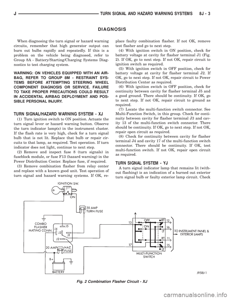
(4) With ignition switch in ON position, check for
battery voltage at cavity for flasher terminal J1 (Fig.
2). If OK, go to next step. If not OK, repair circuit to
ignition switch as required.
(5) With ignition switch in OFF position, check for
battery voltage at cavity for flasher terminal J2. If
OK, go to next step. If not OK, repair circuit to Power
Distribution Center as required.
(6) With ignition switch in OFF position, check for
continuity between cavity for flasher terminal J5 and
a good ground. There should be continuity. If OK, go
to next step. If not OK, repair circuit to ground as
required.
(7) Locate the multi-function switch connector. See
Multi-Function Switch, in this group. Check for conti-
nuity between cavity for flasher terminal J3 and cav-
ity 13 of the multi-function switch connector. There
should be continuity. If OK, go to next step. If not OK,
repair open circuit as required.
(8) Check for continuity between cavity for flasher
terminal J4 and cavity 17 of the multi-function switch
connector. There should be continuity. If OK, test
multi-function switch. If not OK, repair open circuit
as required.
TURN SIGNAL SYSTEM - YJ
A turn signal indicator lamp that remains lit (with-
out flashing) is an indication of a burned out exterior
turn signal bulb or faulty exterior lamp circuit. Check
Fig. 2 Combination Flasher Circuit - XJ
JTURN SIGNAL AND HAZARD WARNING SYSTEMS 8J - 3
Page 430 of 2158
lamps and repair circuits or replace bulbs as re-
quired. If system still does not function properly, pro-
ceed as follows.
(1) Locate fuseblock module under driver's side of
instrument panel. Remove and inspect fuse 4. If OK,
go to next step. If not OK, replace fuse as required.
(2) Replace turn signal flasher (light blue can in
fuseblock module) with a known good unit. Test op-
eration. If OK, replace faulty turn signal flasher. If
not OK, remove test flasher and go to next step.
(3) Turn ignition switch to ACCESSORY position.
Check for battery voltage at flasher cavity on left
(closest to hazard flasher). If OK, go to next step. If
not OK, repair circuit to fuse 4 as required.
(4) Turn ignition switch to OFF position. See Turn
Signal/Hazard Warning Switch Remove/Install to lo-
cate steering column connector. Unplug connector.
(5) Turn ignition switch to ACCESSORY position.
Check for battery voltage at connector terminal L. If
OK, replace turn signal/hazard warning switch. If not
OK, repair circuit between turn signal flasher and
steering column connector.
HAZARD WARNING SYSTEM - YJ
(1) Locate Power Distribution Center (PDC) near
battery tray in engine compartment. Remove and in-
spect fuse F5. If OK, go to next step. If not OK,
replace fuse as required.(2) Replace hazard warning flasher (metal can in
fuseblock module) with a known good unit. Test op-
eration. If OK, replace faulty hazard warning flasher.
If not OK, remove test flasher and go to next step.
(3) Check for battery voltage at flasher cavity on
left (closest to hazard flasher). If OK, go to next step.
If not OK, repair circuit to fuse F5 in PDC as re-
quired.
(4) See Turn Signal/Hazard Warning Switch Re-
move/Install to locate steering column connector. Un-
plug connector.
(5) Check for battery voltage at connector terminal
K. If OK, replace turn signal/hazard warning switch.
If not OK, repair circuit between hazard warning
flasher and steering column connector.
MULTI-FUNCTION SWITCH - XJ
(1) Access multi-function switch connector and re-
move. See service procedures for Multi-Function
Switch, in this group.
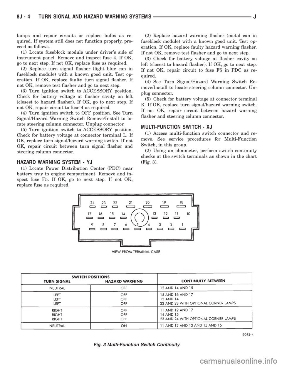
(2) Using an ohmmeter, perform switch continuity
checks at the switch terminals as shown in the chart
(Fig. 3).
Fig. 3 Multi-Function Switch Continuity
8J - 4 TURN SIGNAL AND HAZARD WARNING SYSTEMSJ
Page 431 of 2158
SERVICE PROCEDURES
WARNING: ON VEHICLES EQUIPPED WITH AN AIRBAG,
REFER TO GROUP 8M - RESTRAINT SYSTEMS BEFORE
ATTEMPTING STEERING WHEEL COMPONENT DIAGNO-
SIS OR SERVICE. FAILURE TO TAKE PROPER PRECAU-
TIONS COULD RESULT IN ACCIDENTAL AIRBAG DE-
PLOYMENT AND POSSIBLE PERSONAL INJURY.
MULTI-FUNCTION SWITCH REMOVE/INSTALL - XJ
(1) Disconnect battery negative cable.
(2) Remove tilt lever (if equipped).
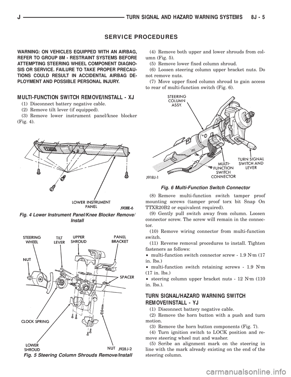
(3) Remove lower instrument panel/knee blocker
(Fig. 4).(4) Remove both upper and lower shrouds from col-
umn (Fig. 5).
(5) Remove lower fixed column shroud.
(6) Loosen steering column upper bracket nuts. Do
not remove nuts.
(7) Move upper fixed column shroud to gain access
to rear of multi-function switch (Fig. 6).
(8) Remove multi-function switch tamper proof
mounting screws (tamper proof torx bit Snap On
TTXR20B2 or equivalent required).
(9) Gently pull switch away from column. Loosen
connector screw. The screw will remain in the connec-
tor.
(10) Remove wiring connector from multi-function
switch.
(11) Reverse removal procedures to install. Tighten
fasteners as follows:
²multi-function switch connector screw - 1.9 Nzm (17
in. lbs.)
²multi-function switch retaining screws - 1.9 Nzm
(17 in. lbs.)
²steering column upper bracket nuts - 12 Nzm(110
in. lbs.).
TURN SIGNAL/HAZARD WARNING SWITCH
REMOVE/INSTALL - YJ
(1) Disconnect battery negative cable.
(2) Remove the horn button with a push and turn
motion.
(3) Remove the horn button components (Fig. 7).
(4) Turn ignition switch to LOCK position and re-
move steering wheel nut and washer.
(5) Scribe an alignment mark on the steering in
line with the mark already existing on the end of the
steering column.
Fig. 5 Steering Column Shrouds Remove/Install
Fig. 4 Lower Instrument Panel/Knee Blocker Remove/
Install
Fig. 6 Multi-Function Switch Connector
JTURN SIGNAL AND HAZARD WARNING SYSTEMS 8J - 5
Page 437 of 2158
DIAGNOSIS - XJ
WINDSHIELD WIPER SYSTEM
(1) Remove in-line circuit breaker near fuseblock
module and turn ignition switch to ACCESSORY or
ON.
(a) Measure voltage at battery side of circuit
breaker cavity. Meter should read battery voltage.
If not OK, repair wiring from ignition switch.
(b) Measure resistance across circuit breaker ter-
minals. Meter should read zero ohms. If not OK,
replace failed circuit breaker.
(2) Unplug wiper motor side of wiring harness con-
nector (gray) from wiper (multi-function) switch side
of wiring harness connector (black), or from intermit-
tent wipe module (if equipped) at base of steering col-
umn. Turn ignition switch to ACCESSORY or ON.
(a) Measure voltage at unplugged wiper motor
side of wiring harness connector (gray) terminal D.
Meter should read battery voltage. If not OK, re-
pair wiring from circuit breaker.
(b) Turn ignition switch to OFF and measure re-
sistance from unplugged wiper motor side of wiring
harness connector (gray) terminal G to ground.
Meter should read zero ohms. If not OK, repair
wiring to ground.
(3) Leave ignition switch in OFF, and back probe
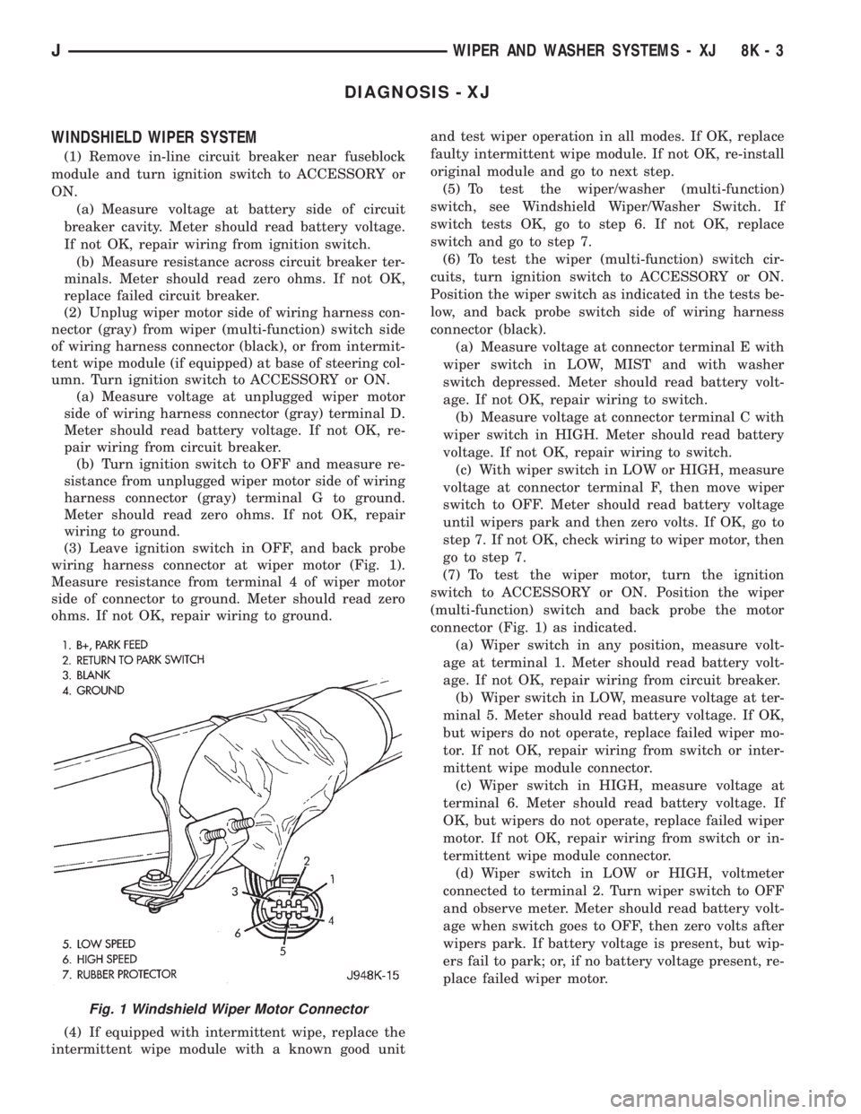
wiring harness connector at wiper motor (Fig. 1).
Measure resistance from terminal 4 of wiper motor
side of connector to ground. Meter should read zero
ohms. If not OK, repair wiring to ground.
(4) If equipped with intermittent wipe, replace the
intermittent wipe module with a known good unitand test wiper operation in all modes. If OK, replace
faulty intermittent wipe module. If not OK, re-install
original module and go to next step.
(5) To test the wiper/washer (multi-function)
switch, see Windshield Wiper/Washer Switch. If
switch tests OK, go to step 6. If not OK, replace
switch and go to step 7.
(6) To test the wiper (multi-function) switch cir-
cuits, turn ignition switch to ACCESSORY or ON.
Position the wiper switch as indicated in the tests be-
low, and back probe switch side of wiring harness
connector (black).
(a) Measure voltage at connector terminal E with
wiper switch in LOW, MIST and with washer
switch depressed. Meter should read battery volt-
age. If not OK, repair wiring to switch.
(b) Measure voltage at connector terminal C with
wiper switch in HIGH. Meter should read battery
voltage. If not OK, repair wiring to switch.
(c) With wiper switch in LOW or HIGH, measure
voltage at connector terminal F, then move wiper
switch to OFF. Meter should read battery voltage
until wipers park and then zero volts. If OK, go to
step 7. If not OK, check wiring to wiper motor, then
go to step 7.
(7) To test the wiper motor, turn the ignition
switch to ACCESSORY or ON. Position the wiper
(multi-function) switch and back probe the motor
connector (Fig. 1) as indicated.
(a) Wiper switch in any position, measure volt-
age at terminal 1. Meter should read battery volt-
age. If not OK, repair wiring from circuit breaker.
(b) Wiper switch in LOW, measure voltage at ter-
minal 5. Meter should read battery voltage. If OK,
but wipers do not operate, replace failed wiper mo-
tor. If not OK, repair wiring from switch or inter-
mittent wipe module connector.
(c) Wiper switch in HIGH, measure voltage at
terminal 6. Meter should read battery voltage. If
OK, but wipers do not operate, replace failed wiper
motor. If not OK, repair wiring from switch or in-
termittent wipe module connector.
(d) Wiper switch in LOW or HIGH, voltmeter
connected to terminal 2. Turn wiper switch to OFF
and observe meter. Meter should read battery volt-
age when switch goes to OFF, then zero volts after
wipers park. If battery voltage is present, but wip-
ers fail to park; or, if no battery voltage present, re-
place failed wiper motor.
Fig. 1 Windshield Wiper Motor Connector
JWIPER AND WASHER SYSTEMS - XJ 8K - 3
Page 438 of 2158

WINDSHIELD WASHER SYSTEM
WITH NON-INTERMITTENT WIPE
(1) Unplug washer pump connector. Measure resis-
tance between terminal B at pump and a clean chas-
sis ground. Meter should read zero ohms. If not OK,
repair open to ground.
(2) Turn ignition switch to ACCESSORY and
washer (multi-function) switch to ON.
(a) Measure voltage at washer pump connector
terminal A. Meter should read battery voltage. If
OK, replace washer pump. If not OK, go to next
step.
(b) Measure voltage at wiper/washer switch con-
nector terminal B. Meter should read battery volt-
age. If OK, repair open to washer pump. If not OK,
replace switch.
WITH INTERMITTENT WIPE
(1) Unplug washer pump connector. Measure resis-
tance between terminal B at pump and a clean chas-
sis ground. Meter should read zero ohms. If not OK,
repair open to ground.
(2) Turn ignition switch to ACCESSORY and
washer (multi-function) switch to ON.
(a) Measure voltage at intermittent wipe module
switch connector terminal B (pink wire). Meter
should read battery voltage. If not OK, replace
wiper switch.
(b) Measure voltage at wipe module motor con-
nector terminal B (brown wire). Meter should read
battery voltage. If not OK, replace module.
(c) Measure voltage at washer pump connector
terminal A at pump. Meter should read battery
voltage. If OK, replace pump. If not OK, repair
open from wipe module.
WINDSHIELD WIPER/WASHER SWITCH
Use an ohmmeter to test for continuity (no resis-
tance) between the terminals of the switch as shown
in the Multi-Function Switch Continuity chart (Fig. 2
or 3).
INTERMITTENT WIPE MODULE
The intermittent wipe module is non-serviceable.
Refer to Group 8W - Wiring Diagrams for more infor-
mation.
The intermittent wipe module is attached to the
lower instrument panel cover near the steering col-
umn with a hook and loop fastener patch.
LIFTGATE WIPER SYSTEM
(1) Remove and inspect fuse 1. Replace faulty fuse,
if required.
(2) Turn ignition switch to ACCESSORY and lift-
gate wiper switch to WASH.(a) Measure voltage at liftgate wiper switch ter-
minal B. Meter should read battery voltage. If not
OK, repair open to fuse 1.
(b) Measure voltage at liftgate wiper switch ter-
minals A, C and D. Meter should read battery volt-
age. If not OK, replace switch.
(3) Turn ignition switch to ACCESSORY, place lift-
gate wiper switch in WIPE. Measure voltage at lift-
Fig. 2 Multi-Function Switch Continuity (Two-Speed
Wipers)
Fig. 3 Multi-Function Switch Continuity (Intermittent
Wipe)
8K - 4 WIPER AND WASHER SYSTEMS - XJJ