1995 JEEP YJ battery
[x] Cancel search: batteryPage 515 of 2158
SERVICE PROCEDURES
POWER SEAT SWITCH REMOVE/INSTALL
(1) Disconnect battery negative cable.
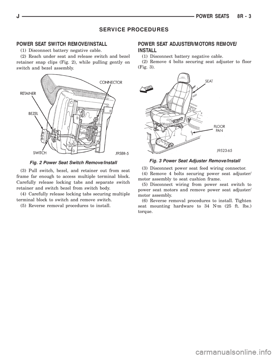
(2) Reach under seat and release switch and bezel
retainer snap clips (Fig. 2), while pulling gently on
switch and bezel assembly.
(3) Pull switch, bezel, and retainer out from seat
frame far enough to access multiple terminal block.
Carefully release locking tabs and separate switch
retainer and switch bezel from switch body.
(4) Carefully release locking tabs securing multiple
terminal block to switch and remove switch.
(5) Reverse removal procedures to install.
POWER SEAT ADJUSTER/MOTORS REMOVE/
INSTALL
(1) Disconnect battery negative cable.
(2) Remove 4 bolts securing seat adjuster to floor
(Fig. 3).
(3) Disconnect power seat feed wiring connector.
(4) Remove 4 bolts securing power seat adjuster/
motor assembly to seat cushion frame.
(5) Disconnect wiring from power seat switch to
power seat motors and remove power seat adjuster/
motor assembly.
(6) Reverse removal procedures to install. Tighten
seat mounting hardware to 34 Nzm (25 ft. lbs.)
torque.
Fig. 2 Power Seat Switch Remove/InstallFig. 3 Power Seat Adjuster Remove/Install
JPOWER SEATS 8R - 3
Page 517 of 2158
POWER WINDOWS
CONTENTS
page page
DIAGNOSIS............................. 1
GENERAL INFORMATION.................. 1SERVICE PROCEDURES................... 7
GENERAL INFORMATION
Power door windows are optional equipment on XJ
(Cherokee) models. The power windows operate only
with the ignition switch in the ON position. This
group covers diagnosis and service of the electrical
components peculiar to the power window system.
For service of mechanical components such as the
regulator, lift plate or window tracks refer to Group
23 - Body Components.
Following are general descriptions of the major
components in the power window system. Refer to
Group 8W - Wiring Diagrams for complete circuit de-
scriptions and diagrams.
POWER WINDOW SWITCH
Both front and rear door windows can be raised or
lowered electrically by operating the four two-way
switches on the driver's door panel. A single two-way
switch on each passenger's door panel operates only
the window on that passenger's door. The switches
cannot be repaired. If faulty, they must be replaced.
POWER WINDOW MOTOR
A permanent magnet reversible motor moves the
window regulator through a cable and drum operat-ing mechanism. A positive and negative battery con-
nection to the two motor terminals will cause the
motor to rotate in one direction. Reversing current
through these same two connections will cause the
motor to rotate in the opposite direction. In addition,
each power window motor is equipped with an inte-
gral automatic re-setting circuit breaker to protect
the motor from overloads. The power window motor
and regulator assembly cannot be repaired. If faulty,
the entire assembly must be replaced.
CIRCUIT BREAKER
An automatic re-setting circuit breaker in the fuse-
block module is used to protect the power window
system circuit. The circuit breaker can protect the
system from a short circuit, and can also protect the
system from an overload condition caused by an ob-
structed or stuck window glass or regulator. The cir-
cuit breaker can not be repaired. If faulty, it must be
replaced.
DIAGNOSIS
It is necessary that the window be free to slide up
and down for the power window system to function
properly. If the window is not free to move up and
down, the motor will overload and trip the circuit
breaker. To determine if the glass is free, disconnect
regulator plate from the glass and slide window up
and down by hand.
An alternate method is to shake the glass in the
door, with the glass positioned between the up and
down stop positions. Check that the glass can be
moved slightly from side to side, front to rear, and up
and down. Then check that window is not boundtight in the tracks. If window is free, proceed with di-
agnosis that follows. If window is not free, refer to
Group 23 - Body Components for service procedures.
CIRCUIT BREAKER
Locate correct circuit breaker in fuseblock module.
Pull out slightly, but be sure that circuit breaker ter-
minals still contact terminals in fuseblock module.
Turn ignition switch to ON position. Connect ground
wire of voltmeter to a good ground. With probe of
voltmeter positive lead, check both terminals of cir-
cuit breaker for battery voltage. If only one terminal
JPOWER WINDOWS 8S - 1
Page 518 of 2158
has battery voltage, circuit breaker is faulty and
must be replaced. If neither terminal has battery
voltage, repair circuit from ignition switch as re-
quired.
POWER WINDOW SWITCH
Before you proceed with this diagnosis, confirm
proper circuit breaker operation. See Circuit Breaker
diagnosis.
(1) Remove switch from door trim panel. See
Power Window Switch Remove/Install. Carefully sep-
arate multiple terminal block on wiring harness from
switch body.
(2) Check for continuity between connector cavity
for switch pin DX and a good ground. See switch con-
tinuity charts for pin identification. There should be
continuity. If OK, go to next step. If not OK, repair
ground circuit as required.
(3) Turn ignition switch to ON position. Check for
battery voltage at connector cavity for switch pin BY.
If OK, go to next step. If not OK, repair wiring to cir-
cuit breaker as required.
(4) Test switch continuity. See switch continuity
charts to determine if continuity is correct in theOFF, LOCK, UP and DOWN switch positions. If OK,
go to Power Window Motor diagnosis. If not OK, re-
place the switch.
POWER WINDOW MOTOR
Before you proceed with this diagnosis, confirm
proper switch operation. See Power Window Switch
diagnosis.
(1) Remove door trim panel (see Power Window
Motor Remove/Install).
(2) Disconnect motor connector. Apply 12 volts
across the motor terminals to check its operation in
one direction. Reverse the polarity to check the oper-
ation in the other direction. Remember, if window is
in the full up or down position the motor will not op-
erate in that direction by design. If OK, repair wire
harness from the motor to the switch as required. If
not OK, replace the motor.
(3) If motor operates in both directions, check op-
eration through its complete up and down travel. If
not OK, refer to Group 23 - Body Components to
check window glass, tracks, and regulator for stick-
ing, binding or improper adjustment.
8S - 2 POWER WINDOWSJ
Page 525 of 2158

POWER MIRRORS
CONTENTS
page page
DIAGNOSIS............................. 1
GENERAL INFORMATION.................. 1SERVICE PROCEDURES................... 4
GENERAL INFORMATION
Power outside rear view mirrors are an available
option on XJ (Cherokee) models. Following are gen-
eral descriptions of the major components in the
power mirror system. Refer to Group 8W - Wiring Di-
agrams for complete circuit descriptions and dia-
grams.
POWER MIRROR
The power mirrors are connected to battery feed at
all times. Each mirror head contains two electric mo-
tors, two drive mechanisms and the mirror glass.
One motor and drive controls mirror up-and-down
movement, and the other controls right-and-left
movement.
The mirror glass is the only serviced replacement
part for the power mirror assembly. If any other com-ponent of the mirror unit is faulty or damaged, the
entire assembly must be replaced.
POWER MIRROR SWITCH
Both the right and left mirror are controlled by a
multi-function switch located on the front of the cen-
ter console storage compartment, directly below the
armrest. The selector switch is moved right (right
mirror control), left (left mirror control), or center to
turn power mirrors off. Then one of four directional
control buttons is depressed to control movement of
the selected mirror up, down, right, or left. The
power mirror switch is serviced only as a complete
unit.
DIAGNOSIS
POWER MIRROR SYSTEM
(1) Check fuse 16 in Power Distribution Center
(PDC) and fuse 9 in fuseblock module. If OK, go to
next step. If not OK, replace fuse.
(2) Check for battery voltage at fuse 9 in fuseblock
module. If OK, go to next step. If not OK, repair cir-
cuit to fuse 16 in PDC.
(3) Remove power mirror switch from the center
console. See Power Mirror Switch Remove/Install.
(4) Disconnect wiring harness connector from
switch. Check for battery voltage at pink wire. If OK,
go to next step. If not OK, repair circuit to fuse 9 in
fuseblock module.
(5) Check for continuity between black wire in
switch harness connector and a good ground. There
should be continuity. If OK, go to next step. If not
OK, repair circuit to ground.
(6) Check switch continuity as shown in the Mirror
Switch Continuity charts. If OK, go to next step. If
not OK, replace switch.(7) See Power Mirror Switch illustration. Connect
a jumper wire from mirror switch connector cavity
for pin E to cavity for pin F. Now connect a second
jumper from connector cavity for pin G to each of the
following pin cavities: A, B, C, then D. In each case,
the selected mirror head should move. If OK, replace
switch. If not OK, go to next step.
(8) Remove door trim panel and unplug power mir-
ror connector inside door. Connect one jumper wire to
a good ground and a second jumper wire to a battery
feed. Connect other ends of jumpers to the mirror
side of connector in door (refer to Group 8W - Wiring
Diagrams for connector cavity identification). Mirror
head should move in each of the four directions. If
OK, repair wiring between mirror switch and door
connectors. If not OK, replace mirror.
JPOWER MIRRORS 8T - 1
Page 528 of 2158
SERVICE PROCEDURES
POWER MIRROR SWITCH REMOVE/INSTALL
(1) Disconnect battery negative cable.
(2) Using a wide flat-bladed tool, pry the switch
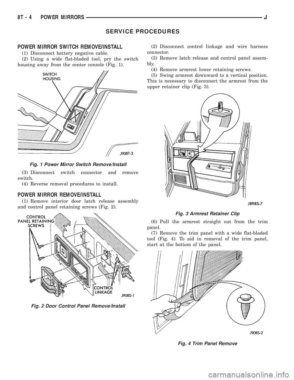
housing away from the center console (Fig. 1).
(3) Disconnect switch connector and remove
switch.
(4) Reverse removal procedures to install.
POWER MIRROR REMOVE/INSTALL
(1) Remove interior door latch release assembly
and control panel retaining screws (Fig. 2).(2) Disconnect control linkage and wire harness
connector.
(3) Remove latch release and control panel assem-
bly.
(4) Remove armrest lower retaining screws.
(5) Swing armrest downward to a vertical position.
This is necessary to disconnect the armrest from the
upper retainer clip (Fig. 3).
(6) Pull the armrest straight out from the trim
panel.
(7) Remove the trim panel with a wide flat-bladed
tool (Fig. 4). To aid in removal of the trim panel,
start at the bottom of the panel.
Fig. 1 Power Mirror Switch Remove/Install
Fig. 2 Door Control Panel Remove/Install
Fig. 3 Armrest Retainer Clip
Fig. 4 Trim Panel Remove
8T - 4 POWER MIRRORSJ
Page 531 of 2158
CHIME/BUZZER WARNING SYSTEMS
CONTENTS
page page
DIAGNOSIS............................. 2
GENERAL INFORMATION.................. 1SERVICE PROCEDURES................... 4
GENERAL INFORMATION
This group covers the buzzer warning system,
which is standard equipment on XJ (Cherokee)/YJ
(Wrangler) models. The system provides an audible
warning to the driver when it monitors the following
conditions:
²key is in ignition switch with the driver's door
open
²head or park lamps are on with driver's door open
(XJ only)
²driver's seat belt is not buckled with ignition
switch in ON position.
Following are general descriptions of the major
components in the buzzer warning system. Refer to
Group 8W - Wiring Diagrams for complete circuit de-
scriptions and diagrams.
BUZZER MODULE
The buzzer module is located in the fuseblock mod-
ule under the left end of the instrument panel. It re-
ceives battery voltage at all times from (fuse 15 - XJ,
fuse 3 - YJ) the fuseblock module. It also receives a
second battery feed (fuse 17 - XJ, fuse 9 - YJ) when
the ignition switch is in the ON or START position.
Other inputs to the module include the driver's door
jamb switch, the driver's seat belt switch, the ignition
key-in switch, and the headlamp switch (XJ only). The
only output of the module is a timed 4 to 8 second feed
to the seat belt reminder lamp in the message center of
the instrument cluster. The timer function begins after
the ignition switch is turned to the ON position.
The buzzer module can not be repaired. If faulty, it
must be replaced.
DRIVER'S DOOR JAMB SWITCH
The driver's door jamb switch is mounted to the
driver's door hinge pillar. The switch closes a path to
ground for the buzzer module through the key-in
switch or headlamp switch (XJ only) when the driv-
er's door is opened, and opens when the driver's door
is closed. This switch can not be repaired. If faulty, it
must be replaced.
IGNITION KEY-IN SWITCH
XJ MODELS
The key-in switch is integral to the ignition switch,
which is mounted on the right side of the steering col-
umn. It closes a path to ground for the buzzer module
when the ignition key is inserted in the ignition lock cyl-
inder and the driver's door jamb switch is closed (door
open). The switch opens when the key is removed from
the ignition lock cylinder. This switch can not be re-
paired. If faulty, the entire ignition switch must be re-
placed. Refer to Group 8D - Ignition Systems for service
procedures.
YJ MODELS
The key-in switch is mounted within the steering col-
umn in the lock cylinder housing. It closes a path to
ground for the buzzer module when the ignition key is
inserted in the ignition lock cylinder and the driver's
door jamb switch is closed (door open). The switch opens
when the key is removed from the ignition lock cylinder.
This switch is available for service replacement. Refer
to Group 19 - Steering for service procedures.
HEADLAMP SWITCH (XJ ONLY)
The headlamp switch is located in the instrument
panel. It closes a path to ground for the buzzer module
when the park or headlamps are on and the driver's
door jamb switch is closed (door open). The switch opens
the ground path when the park and headlamps are
turned off. The headlamp switch can not be repaired. If
faulty, it must be replaced. Refer to Group 8E - Instru-
ment Panel and Gauges for service procedures.
DRIVER'S SEAT BELT SWITCH
The driver's seat belt switch is integral to the driv-
er's seat belt buckle-half assembly. The switch is nor-
mally closed, providing a ground path to the buzzer
module. When the tip-half of the seat belt is inserted
into the seat belt buckle, the switch opens the buzzer
module ground path. The seat belt switch can not be
repaired. If faulty, the entire driver's seat belt buck-
le-half must be replaced. Refer to Group 23 - Body
Components for service procedures.
JCHIME/BUZZER WARNING SYSTEMS 8U - 1
Page 532 of 2158
DIAGNOSIS
BUZZER MODULE
(1) Check fuses (15 and 17 - XJ, 3 and 9 - YJ) in
the fuseblock module. If fuses are OK, go to next
step. If not OK, replace fuses as required.
(2) Check for battery voltage at fuse (15 - XJ, 3 -
YJ) in fuseblock module. If OK, go to next step. If not
OK, repair feed circuit from power distribution center
as required.
(3) Turn ignition switch to ON position. Check for
battery voltage at fuse (17 - XJ, 9 - YJ) in the fuse-
block module. If OK, go to next step. If not OK, re-
pair feed from ignition switch as required.
(4) Turn ignition switch to OFF position. Replace
buzzer module with a known good unit and test op-
eration. If not OK, remove buzzer module and go to
next step.
(5) Check for battery voltage at cavity for buzzer
terminal 7 in buzzer module connector (Fig. 1). If
OK, go to next step. If not OK, repair circuit to fuse
(15 - XJ, 3 - YJ).
(6) Turn ignition switch to ON position. Check for
battery voltage at cavity for buzzer terminal 1 in
buzzer module connector. If OK, go to next step. If
not OK, repair circuit to fuse (17 - XJ, 9 - YJ) in fuse-
block module.
(7) Turn ignition switch to OFF position. Check for
continuity between cavity for buzzer terminal 3 and
a good ground. There should be continuity. If OK, go
to diagnosis for switch that is related to buzzer mal-
function. If not OK, repair circuit to ground as re-
quired.
DRIVER'S DOOR JAMB SWITCH
(1) Open driver's door and note whether interior
lamps light. They should light. If OK, see diagnosis
for Ignition Key-In Switch (XJ or YJ) or Headlamp
Switch (XJ only). If not OK, go to next step.
(2) Check for continuity between door jamb switch
body and a good ground. There should be continuity.
If OK, go to next step. If not OK, tighten or clean
switch attachment to hinge pillar as required to re-
store ground path.
(3) Remove switch from hinge pillar and check
wire connections for clean and tight engagement. If
OK, replace faulty switch. If not OK, clean and
tighten connections as required.
IGNITION KEY-IN SWITCH
XJ MODELS
(1) Remove steering column shrouds (refer to
Group 8D - Ignition Systems for procedure). Unplug
ignition key-in switch connector from ignition switch
(Fig. 3). Open driver's door. Check for continuity be-
tween cavity 4 (black/light blue wire) and a good
ground. There should be continuity. If OK, go to next
step. If not OK, repair circuit to driver's door jamb
switch as required.
(2) Insert ignition key in ignition lock cylinder.
Check for continuity between key-in switch cavities 3
and 4 (Fig. 4). There should be continuity until key is
removed. If OK, go to next step. If not OK, replace
ignition switch.
(3) Check for continuity between key-in switch har-
ness connector cavity 3 (light blue wire) and cavity
for terminal 6 of buzzer module in buzzer module
connector. There should be continuity. If not OK, re-
pair circuit from switch to buzzer module as re-
quired.
Fig. 1 Buzzer Module Connector
Fig. 2 Buzzer Module Terminals
8U - 2 CHIME/BUZZER WARNING SYSTEMSJ
Page 535 of 2158
WIRING DIAGRAMSÐGENERAL INFORMATION
INDEX
page page
Circuit Identification......................... 1
Connector and Terminal Replacement........... 7
Connector Replacement..................... 6
Connectors............................... 2
Diode Replacement........................ 8
Electrostatic Discharge (ESC) Sensitive Devices . . . 2
General Information......................... 1
Intermittent and Poor Connections.............. 4
Notes, Cautions, and Warnings................ 1Symbols................................. 2
Take Outs................................ 2
Terminal Replacement....................... 8
Terminal/Connector RepairÐMolex Connectors.... 6
Troubleshooting Tests....................... 4
Troubleshooting Tools....................... 4
Troubleshooting Wiring Problems.............. 5
Wire Code Identification..................... 1
Wiring Repair............................. 6
GENERAL INFORMATION
This Group is divided into three stand alone sec-
tions; XJ, YJ, and XJ Right Hand Drive (XJ-RHD).
Separate circuit descriptions and wiring diagrams are
provided for each vehicle. Each section contains a
Contents list for the wiring diagrams and circuit de-
scriptions for that vehicle.
The complete XJ circuit descriptions and diagrams
are printed first, followed by those for the YJ and
then the XJ-RHD. The heading at the top of each
page identifies the vehicle covered in the section.
NOTES, CAUTIONS, and WARNINGS
Throughout this group additional important infor-
mation is presented in three ways; Notes, Cautions,
and Warnings.
NOTESare used to help describe how switches or
components operate to complete a particular circuit.
They are also used to indicate different conditions
that may appear on the vehicle. For example, an
up-to and after condition.
CAUTIONSare used to indicate information that
could prevent making an error that may damage the
vehicle.
WARNINGSprovide information to prevent per-
sonal injury and vehicle damage. Below is a list of
general warnings that should be followed any time a
vehicle is being serviced.
ALWAYS WEAR SAFETY GLASSES FOR EYE PRO-
TECTION.
USE SAFETY STANDS ANYTIME A PROCEDURE RE-
QUIRES BEING UNDER A VEHICLE.
BE SURE THAT THE IGNITION SWITCH ALWAYS IS
IN THE OFF POSITION, UNLESS THE PROCEDURE
REQUIRES IT TO BE ON.SET THE PARKING BRAKE WHEN WORKING ON
ANY VEHICLE. AN AUTOMATIC TRANSMISSION
SHOULD BE IN PARK. A MANUAL TRANSMISSION
SHOULD BE IN NEUTRAL.
OPERATE THE ENGINE ONLY IN A WELL-VENTI-
LATED AREA.
KEEP AWAY FROM MOVING PARTS WHEN THE EN-
GINE IS RUNNING, ESPECIALLY THE FAN AND BELTS.
TO PREVENT SERIOUS BURNS, AVOID CONTACT
WITH HOT PARTS SUCH AS THE RADIATOR, EX-
HAUST MANIFOLD(S), TAIL PIPE, CATALYTIC CON-
VERTER, AND MUFFLER.
DO NOT ALLOW FLAME OR SPARKS NEAR THE
BATTERY. GASES ARE ALWAYS PRESENT IN AND
AROUND THE BATTERY.
ALWAYS REMOVE RINGS, WATCHES, LOOSE
HANGING JEWELRY, AND LOOSE CLOTHING.
WIRE CODE IDENTIFICATION
Each wire shown in the diagrams contains a code
(Fig. 1) which identifies the main circuit, part of the
main circuit, gauge of wire, and color. The color is
shown as a two letter code which can be identified by
referring to the Wire Color Code Chart (Fig. 2).
CIRCUIT IDENTIFICATION
All circuits in the diagrams use an alpha/numeric
code to identify the wire and its function (Fig. 3). To
identify which circuit code applies to a system, refer
to the Circuit Identification Code Chart. This chart
shows the main circuits only and does not show the
secondary codes that may apply to some models.
JWIRING DIAGRAMSÐGENERAL INFORMATION 8W - 1