1995 JEEP YJ instrument panel
[x] Cancel search: instrument panelPage 470 of 2158
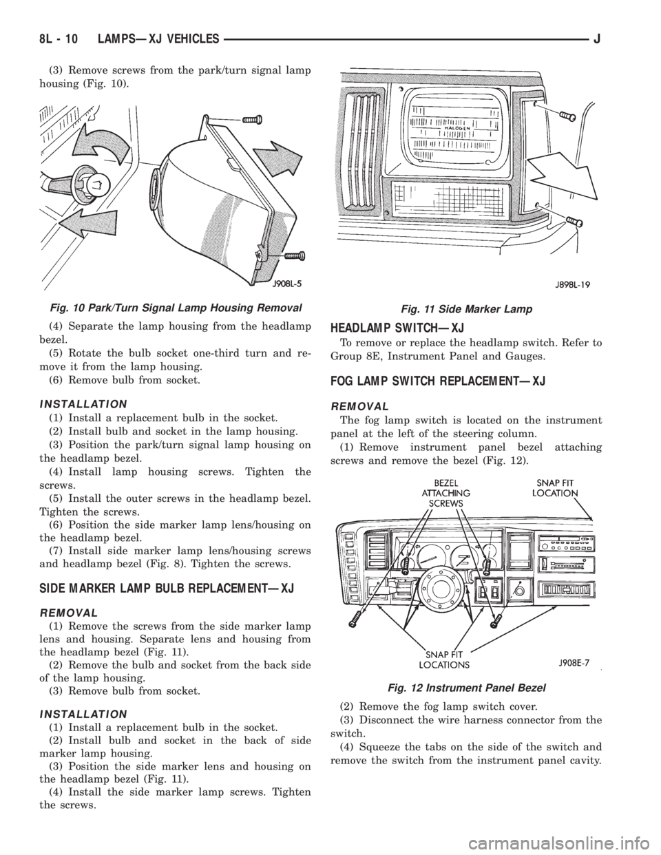
(3) Remove screws from the park/turn signal lamp
housing (Fig. 10).
(4) Separate the lamp housing from the headlamp
bezel.
(5) Rotate the bulb socket one-third turn and re-
move it from the lamp housing.
(6) Remove bulb from socket.
INSTALLATION
(1) Install a replacement bulb in the socket.
(2) Install bulb and socket in the lamp housing.
(3) Position the park/turn signal lamp housing on
the headlamp bezel.
(4) Install lamp housing screws. Tighten the
screws.
(5) Install the outer screws in the headlamp bezel.
Tighten the screws.
(6) Position the side marker lamp lens/housing on
the headlamp bezel.
(7) Install side marker lamp lens/housing screws
and headlamp bezel (Fig. 8). Tighten the screws.
SIDE MARKER LAMP BULB REPLACEMENTÐXJ
REMOVAL
(1) Remove the screws from the side marker lamp
lens and housing. Separate lens and housing from
the headlamp bezel (Fig. 11).
(2) Remove the bulb and socket from the back side
of the lamp housing.
(3) Remove bulb from socket.
INSTALLATION
(1) Install a replacement bulb in the socket.
(2) Install bulb and socket in the back of side
marker lamp housing.
(3) Position the side marker lens and housing on
the headlamp bezel (Fig. 11).
(4) Install the side marker lamp screws. Tighten
the screws.
HEADLAMP SWITCHÐXJ
To remove or replace the headlamp switch. Refer to
Group 8E, Instrument Panel and Gauges.
FOG LAMP SWITCH REPLACEMENTÐXJ
REMOVAL
The fog lamp switch is located on the instrument
panel at the left of the steering column.
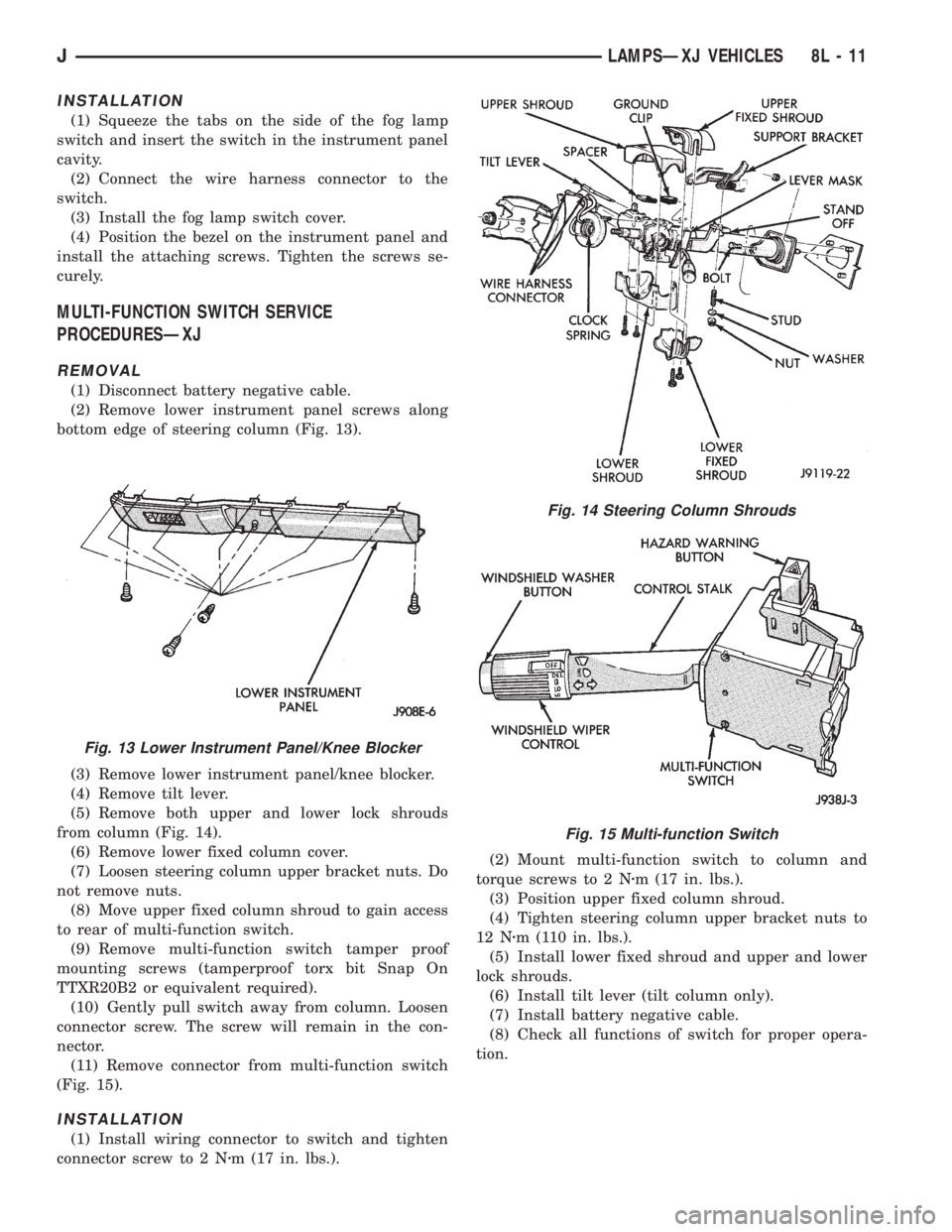
(1) Remove instrument panel bezel attaching
screws and remove the bezel (Fig. 12).
(2) Remove the fog lamp switch cover.
(3) Disconnect the wire harness connector from the
switch.
(4) Squeeze the tabs on the side of the switch and
remove the switch from the instrument panel cavity.
Fig. 10 Park/Turn Signal Lamp Housing RemovalFig. 11 Side Marker Lamp
Fig. 12 Instrument Panel Bezel
8L - 10 LAMPSÐXJ VEHICLESJ
Page 471 of 2158
INSTALLATION
(1) Squeeze the tabs on the side of the fog lamp
switch and insert the switch in the instrument panel
cavity.
(2) Connect the wire harness connector to the
switch.
(3) Install the fog lamp switch cover.
(4) Position the bezel on the instrument panel and
install the attaching screws. Tighten the screws se-
curely.
MULTI-FUNCTION SWITCH SERVICE
PROCEDURESÐXJ
REMOVAL
(1) Disconnect battery negative cable.
(2) Remove lower instrument panel screws along
bottom edge of steering column (Fig. 13).
(3) Remove lower instrument panel/knee blocker.
(4) Remove tilt lever.
(5) Remove both upper and lower lock shrouds
from column (Fig. 14).
(6) Remove lower fixed column cover.
(7) Loosen steering column upper bracket nuts. Do
not remove nuts.
(8) Move upper fixed column shroud to gain access
to rear of multi-function switch.
(9) Remove multi-function switch tamper proof
mounting screws (tamperproof torx bit Snap On
TTXR20B2 or equivalent required).
(10) Gently pull switch away from column. Loosen
connector screw. The screw will remain in the con-
nector.
(11) Remove connector from multi-function switch
(Fig. 15).
INSTALLATION
(1) Install wiring connector to switch and tighten
connector screw to 2 Nzm (17 in. lbs.).(2) Mount multi-function switch to column and
torque screws to 2 Nzm (17 in. lbs.).
(3) Position upper fixed column shroud.
(4) Tighten steering column upper bracket nuts to
12 Nzm (110 in. lbs.).
(5) Install lower fixed shroud and upper and lower
lock shrouds.
(6) Install tilt lever (tilt column only).
(7) Install battery negative cable.
(8) Check all functions of switch for proper opera-
tion.
Fig. 13 Lower Instrument Panel/Knee Blocker
Fig. 14 Steering Column Shrouds
Fig. 15 Multi-function Switch
JLAMPSÐXJ VEHICLES 8L - 11
Page 474 of 2158
INSTALLATION
(1) Position the underhood lamp on the hood inner
panel.
(2) Install the attaching screw through the lamp
and into the hood panel. Tighten the screw securely.
(3) Insert a replacement bulb in the lamp base
socket and rotate it clockwise.
(4) Connect the wire harness connector to the
lamp.
SENTINEL HEADLAMP DELAY MODULEÐXJ
SERVICE INFORMATION
The Headlamp Module delays the de-activation of
the headlamps for 45615 seconds after the ignition
switch is turned OFF. The driver engages the module
by turning the ignition switch OFF, then turning the
headlamps OFF.
The headlamp delay module is located behind the
I/P next to the headlamp switch.
HEADLAMP DELAY MODULE REPLACEMENTÐXJ
The headlamp delay module is attached to the in-
side of the instrument panel to the right of the head-
lamp switch.
REMOVAL
(1) Remove the lower instrument panel.(2) Remove the screw that attaches the module to
the inside of the instrument panel.
(3) Disconnect the wire harness connector and re-
move the module from the instrument panel.
INSTALLATION
(1) Position the module inside the I/P and connect
the wire harness connector to the module.
(2) Install the screw that attaches the module to
the inside of the instrument panel.
(3) Remove the lower instrument panel.
HEADLAMP DELAY FUNCTION TROUBLE
DIAGNOSISÐXJ
DELAY FUNCTION INOPERATIVE
(1) Remove, inspect and test the HD LP DLY fuse.
Replace if defective.
(2) Remove the delay module from the I/P. Do not
disconnect the wire harness connector. Turn the igni-
tion switch to the RUN position. Place the headlamp
switch in headlamps ON position. Turn the ignition
to the OFF position for a resistance test.
(3) Measure the resistance from the delay module
terminal 4 to vehicle body ground. The ohmmeter
should indicate zero ohms. If not, repair the open cir-
cuit in the wire harness to vehicle body ground.
(4) Measure the voltage between the delay module
terminal 8 and vehicle body ground. The voltmeter
should indicate battery voltage. If not, repair the
open circuit in the wire harness to the instrument
cluster indicator connector terminal 14.
(5) Measure the voltage between the delay module
terminal 6 and vehicle body ground. The voltmeter
should indicate battery voltage. If not, repair the
open circuit in the wire harness to the headlamp
switch.
(6) Measure the voltage between the delay module
terminal 2 and vehicle body ground. The voltmeter
should indicate battery voltage. If not, repair the
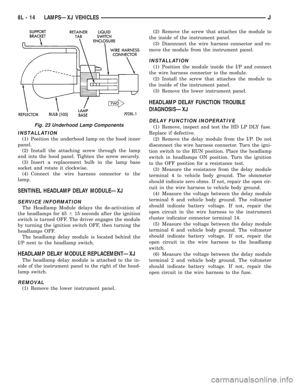
open circuit in the wire harness to the fuse.Fig. 23 Underhood Lamp Components
8L - 14 LAMPSÐXJ VEHICLESJ
Page 478 of 2158

BULB APPLICATIONÐXJ VEHICLES
GENERAL INFORMATION
The following Bulb Application Table lists the lamp
title on the left side of the column and trade number
or part number on the right.
CAUTION: Do not use bulbs that have a higher can-
dle power than the bulb listed in the Bulb Applica-
tion Table. Damage to lamp can result.
Do not touch halogen bulbs with fingers or other
oily surfaces. Bulb life will be reduced.
EXTERIOR LAMPSÐXJ
Back-up .................................................................1156
Center High Mounted Stoplamp ..........................922
Fog ............................................................................H3
Front Side Marker .................................................194
Headlamp/Sealed Beam....................................H6054
License Plate ..........................................................168
License Plate W/Outside Spare ..............................67
Park/Turn Signal ............................................2057NA
Tail/Stop ................................................................2057
Turn Signal ...........................................................1156
INTERIOR LAMPSÐXJ
Service procedures for most of the lamps in the in-
strument panel, Instrument cluster and switches are
located in Group 8E, Instrument Panel and Gauges.
Some components have lamps that can only be ser-
viced by an Authorized Service Center (ASC) after
the component is removed from the vehicle. Contact
local dealer for location of nearest ASC.
Cargo .......................................................................561
Dome .......................................................................561
Dome/Reading.........................................................906Glove Compartment ...............................................194
Overhead Console ..................................................912
Under Hood ............................................................105
Vanity Mirror ...........................................................74
Underpanel Courtesy.............................................168
INDICATOR LAMPS
Service procedures for most of the lamps in the in-
strument panel, instrument cluster and switches are
located in Group 8E, Instrument Panel and Gauges.
A/C Control ...............................................................74
Airbag ........................................................................74
Anti-lock Brake ........................................................74
Ash Receiver .........................................................1891
Brake Warning .........................................................74
Check Engine ...........................................................74
Cigar Lighter ............................................................53
Diesel Wait ...............................................................74
Fasten Seat Belts ....................................................74
Four Wheel Drive ....................................................74
Generator ................................................................194
Generator/Diesel.......................................................74
Heater Control .........................................................74
High Beam..............................................................194
Illumination ............................................................194
Low Fuel .................................................................194
Low Washer Fluid....................................................74
Radio ......................................................................ASC
Rocker Switch...........................................................37
Seat Belt ...................................................................74
Transfer Case .........................................................658
Transmission Floor Shift.......................................658
Turn Signal.............................................................194
Shift ...........................................................................74
Water In Fuel ...........................................................74
8L - 18 LAMPSÐXJ VEHICLESJ
Page 486 of 2158
HEADLAMP SWITCHÐYJ
To remove or replace the headlamp switch, refer to
Group 8E, Instrument Panel and Gauges.
FOG LAMP SWITCH REPLACEMENTÐYJ
REMOVAL
The fog lamp switch is located on the instrument
panel at the right of the steering column. The fog
lamp circuit relay is located below the left headlamp.
(1) Disconnect the battery negative cable.
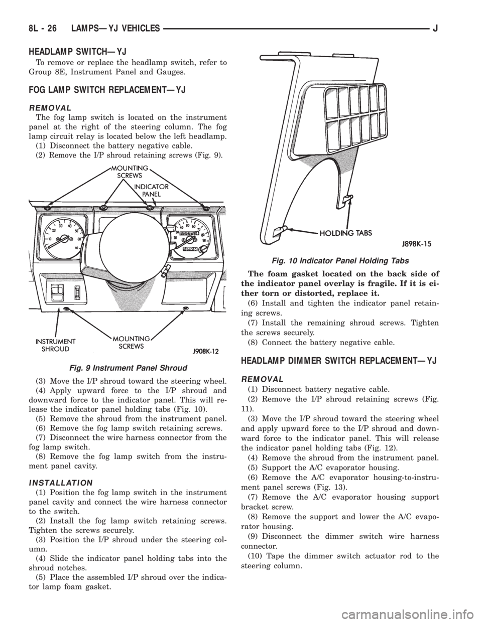
(2) Remove the I/P shroud retaining screws (Fig. 9).
(3) Move the I/P shroud toward the steering wheel.
(4) Apply upward force to the I/P shroud and
downward force to the indicator panel. This will re-
lease the indicator panel holding tabs (Fig. 10).
(5) Remove the shroud from the instrument panel.
(6) Remove the fog lamp switch retaining screws.
(7) Disconnect the wire harness connector from the
fog lamp switch.
(8) Remove the fog lamp switch from the instru-
ment panel cavity.
INSTALLATION
(1) Position the fog lamp switch in the instrument
panel cavity and connect the wire harness connector
to the switch.
(2) Install the fog lamp switch retaining screws.
Tighten the screws securely.
(3) Position the I/P shroud under the steering col-
umn.
(4) Slide the indicator panel holding tabs into the
shroud notches.
(5) Place the assembled I/P shroud over the indica-
tor lamp foam gasket.The foam gasket located on the back side of
the indicator panel overlay is fragile. If it is ei-
ther torn or distorted, replace it.
(6) Install and tighten the indicator panel retain-
ing screws.
(7) Install the remaining shroud screws. Tighten
the screws securely.
(8) Connect the battery negative cable.
HEADLAMP DIMMER SWITCH REPLACEMENTÐYJ
REMOVAL
(1) Disconnect battery negative cable.
(2) Remove the I/P shroud retaining screws (Fig.
11).
(3) Move the I/P shroud toward the steering wheel
and apply upward force to the I/P shroud and down-
ward force to the indicator panel. This will release
the indicator panel holding tabs (Fig. 12).
(4) Remove the shroud from the instrument panel.
(5) Support the A/C evaporator housing.
(6) Remove the A/C evaporator housing-to-instru-
ment panel screws (Fig. 13).
(7) Remove the A/C evaporator housing support
bracket screw.
(8) Remove the support and lower the A/C evapo-
rator housing.
(9) Disconnect the dimmer switch wire harness
connector.
(10) Tape the dimmer switch actuator rod to the
steering column.
Fig. 9 Instrument Panel Shroud
Fig. 10 Indicator Panel Holding Tabs
8L - 26 LAMPSÐYJ VEHICLESJ
Page 487 of 2158
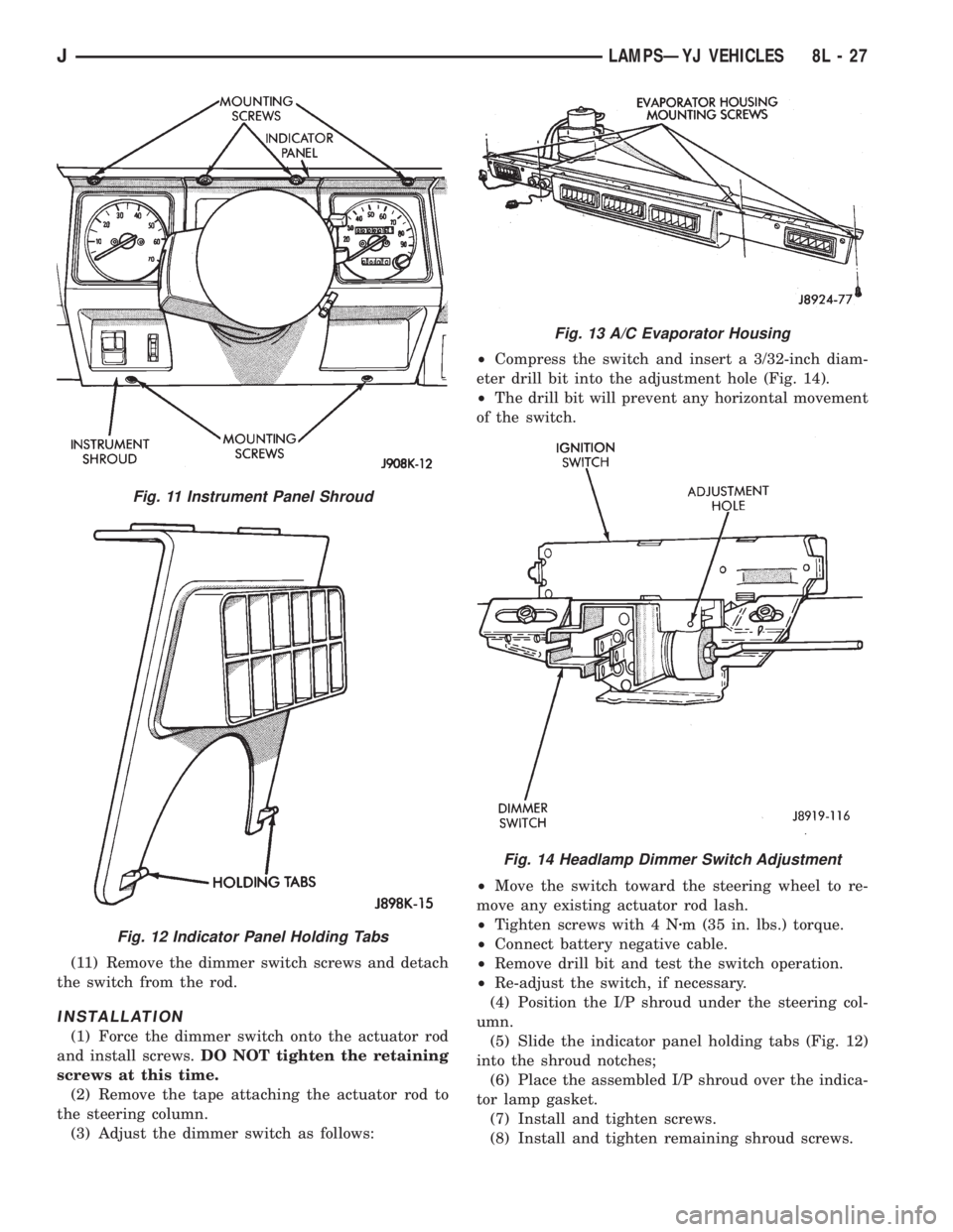
(11) Remove the dimmer switch screws and detach
the switch from the rod.
INSTALLATION
(1) Force the dimmer switch onto the actuator rod
and install screws.DO NOT tighten the retaining
screws at this time.
(2) Remove the tape attaching the actuator rod to
the steering column.
(3) Adjust the dimmer switch as follows:²Compress the switch and insert a 3/32-inch diam-
eter drill bit into the adjustment hole (Fig. 14).
²The drill bit will prevent any horizontal movement
of the switch.
²Move the switch toward the steering wheel to re-
move any existing actuator rod lash.
²Tighten screws with 4 Nzm (35 in. lbs.) torque.
²Connect battery negative cable.
²Remove drill bit and test the switch operation.
²Re-adjust the switch, if necessary.
(4) Position the I/P shroud under the steering col-
umn.
(5) Slide the indicator panel holding tabs (Fig. 12)
into the shroud notches;
(6) Place the assembled I/P shroud over the indica-
tor lamp gasket.
(7) Install and tighten screws.
(8) Install and tighten remaining shroud screws.
Fig. 11 Instrument Panel Shroud
Fig. 12 Indicator Panel Holding Tabs
Fig. 13 A/C Evaporator Housing
Fig. 14 Headlamp Dimmer Switch Adjustment
JLAMPSÐYJ VEHICLES 8L - 27
Page 488 of 2158
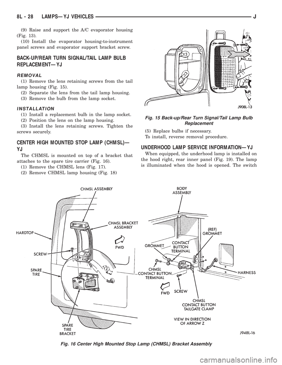
(9) Raise and support the A/C evaporator housing
(Fig. 13).
(10) Install the evaporator housing-to-instrument
panel screws and evaporator support bracket screw.
BACK-UP/REAR TURN SIGNAL/TAIL LAMP BULB
REPLACEMENTÐYJ
REMOVAL
(1) Remove the lens retaining screws from the tail
lamp housing (Fig. 15).
(2) Separate the lens from the tail lamp housing.
(3) Remove the bulb from the lamp socket.
INSTALLATION
(1) Install a replacement bulb in the lamp socket.
(2) Position the lens on the lamp housing.
(3) Install the lens retaining screws. Tighten the
screws securely.
CENTER HIGH MOUNTED STOP LAMP (CHMSL)Ð
YJ
The CHMSL is mounted on top of a bracket that
attaches to the spare tire carrier (Fig. 16).
(1) Remove the CHMSL lens (Fig. 17).
(2) Remove CHMSL lamp housing (Fig. 18)(5) Replace bulbs if necessary.
To install, reverse removal procedure.
UNDERHOOD LAMP SERVICE INFORMATIONÐYJ
When equipped, the underhood lamp is installed on
the hood right, rear inner panel (Fig. 19). The lamp
is illuminated when the hood is opened. The switch
Fig. 15 Back-up/Rear Turn Signal/Tail Lamp Bulb
Replacement
Fig. 16 Center High Mounted Stop Lamp (CHMSL) Bracket Assembly
8L - 28 LAMPSÐYJ VEHICLESJ
Page 492 of 2158

BULB APPLICATIONÐYJ VEHICLES
GENERAL INFORMATION
The following Bulb Application Table lists the lamp
title on the left side of the column and trade number
or part number on the right.
CAUTION: Do not use bulbs that have a higher can-
dle power than the bulb listed in the Bulb Applica-
tion Table. Damage to lamp can result.
Do not touch halogen bulbs with fingers or other
oily surfaces. Bulb life will be reduced.
EXTERIOR LAMPSÐYJ
Back-up .................................................................1156
Center High Mounted Stoplamp ..........................912
Fog ............................................................................H3
Front Side Marker .................................................194
Headlamp/Sealed Beam....................................H6054
Park/Turn Signal..................................................3157
Tail/Stop ................................................................1157
INTERIOR LAMPSÐYJ
Service procedures for most of the lamps in the in-
strument panel, Instrument cluster and switches are
located in Group 8E, Instrument Panel and Gauges.
Some components have lamps that can only be ser-
viced by an Authorized Service Center (ASC) after
the component is removed from the vehicle. Contact
local dealer for location of nearest ASC.Dome/Cargo .........................................................212-2
Glove Compartment ...............................................194
Under Hood ............................................................105
Underpanel Courtesy...............................................89
INDICATOR LAMPS
Service procedures for most of the lamps in the in-
strument panel, instrument cluster and switches are
located in Group 8E, Instrument Panel and Gauges.
A/C Control ...............................................................74
Anti-lock Brake ........................................................74
Ash Receiver .........................................................1891
Brake Warning .........................................................74
Cigar Lighter ............................................................53
Fasten Seat Belts ....................................................74
Four Wheel Drive ....................................................74
Generator ................................................................194
Hazard.......................................................................74
Heater Control .......................................................194
High Beam..............................................................194
Illumination ............................................................194
Low Coolant..............................................................74
Radio ......................................................................ASC
Rocker Switch...........................................................74
Seat Belt ...................................................................74
Shift ...........................................................................74
Turn Signal.............................................................194
8L - 32 LAMPSÐYJ VEHICLESJ