1995 JEEP YJ instrument panel
[x] Cancel search: instrument panelPage 404 of 2158

RADIO ILLUMINATION RELAY
If the relay fails any one of Relay Tests, it is faulty
and should be replaced. If the relay passes the Relay
Tests, proceed to the Relay Circuit Tests.
On XJ models, the radio illumination relay is lo-
cated in the relay center (Fig. 2), which is fastened to
the lower instrument panel reinforcement behind the
lower instrument panel near the steering column. On
YJ models, the relay is taped to the instrument panel
wiring harness above and to the right of the radio,
near the glove box.
RELAY TESTS
Remove relay to perform the following tests:
(1) A relay in the de-energized position should
have continuity between terminals 87A and 30, and
no continuity between terminals 87 and 30.(2) Resistance value between terminals 85 and 86
(electromagnet) is 7565 ohms.
(3) Connect a battery to terminals 85 and 86. There
should now be continuity between terminals 30 and 87,
and no continuity between terminals 87A and 30.
RELAY CIRCUIT TESTS
With relay still removed, perform the following
tests:
(1) The common feed terminal (30) is connected to
the radio display feed circuit. There should be conti-
nuity between cavity for relay terminal 30 and clock/
radio display feed cavity of radio connector at all
times. If not, repair circuit as required.
(2) The normally closed terminal (87A) is connected
to terminal 30 in the de-energized position. This circuit
provides ignition-switched battery voltage to the radio
display when the headlamp switch is off. There should
be battery voltage present at cavity for relay terminal
87A with the ignition switch in the ON position. If not,
repair circuit to ignition switch as required.
(3) The normally open terminal (87) is connected to
terminal 30 in the energized position. This circuit
provides instrument panel dimmer controlled feed to
the radio display when the headlamp switch is on.
There should be voltage present at cavity for relay
terminal 87 when the headlamp switch is on. Also,
the voltage reading should vary as the panel dimmer
switch is rotated. If not, repair circuit or panel dim-
mer switch as required.
(4) The coil battery terminal (86) connected to the
electromagnet in the relay. Check as follows:
(a) On YJ models, it is energized when the head-
lamp switch is on. There should be battery voltage at
cavity for relay terminal 86 with the headlamp switch
on. If not, repair circuit to headlamp switch as re-
quired.
(b) On XJ models, it is grounded at all times.
There should be continuity to ground at cavity for
relay terminal 86 at all times. If not, repair circuit
to ground as required.
RADIO CONNECTIONS
Fig. 2 Radio Illumination Relay - XJ
RADIO ILLUMINATION RELAY CONNECTIONS
8F - 4 AUDIO SYSTEMSJ
Page 406 of 2158
SERVICE PROCEDURES
RADIO REMOVE/INSTALL - XJ
(1) Disconnect battery negative cable.
(2) Remove upper and lower steering column
shrouds and steering column to instrument panel be-
zel gap hider. If equipped with tilt steering, apply
tape to tilt mechanism on top of steering column to
protect instrument panel bezel from damage during
removal.
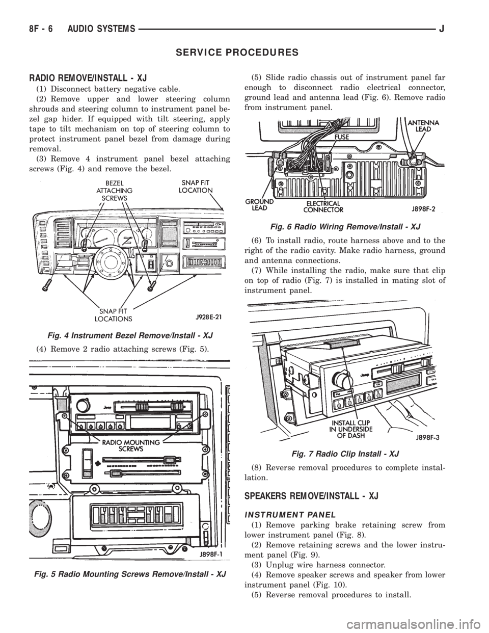
(3) Remove 4 instrument panel bezel attaching
screws (Fig. 4) and remove the bezel.
(4) Remove 2 radio attaching screws (Fig. 5).(5) Slide radio chassis out of instrument panel far
enough to disconnect radio electrical connector,
ground lead and antenna lead (Fig. 6). Remove radio
from instrument panel.
(6) To install radio, route harness above and to the
right of the radio cavity. Make radio harness, ground
and antenna connections.
(7) While installing the radio, make sure that clip
on top of radio (Fig. 7) is installed in mating slot of
instrument panel.
(8) Reverse removal procedures to complete instal-
lation.
SPEAKERS REMOVE/INSTALL - XJ
INSTRUMENT PANEL
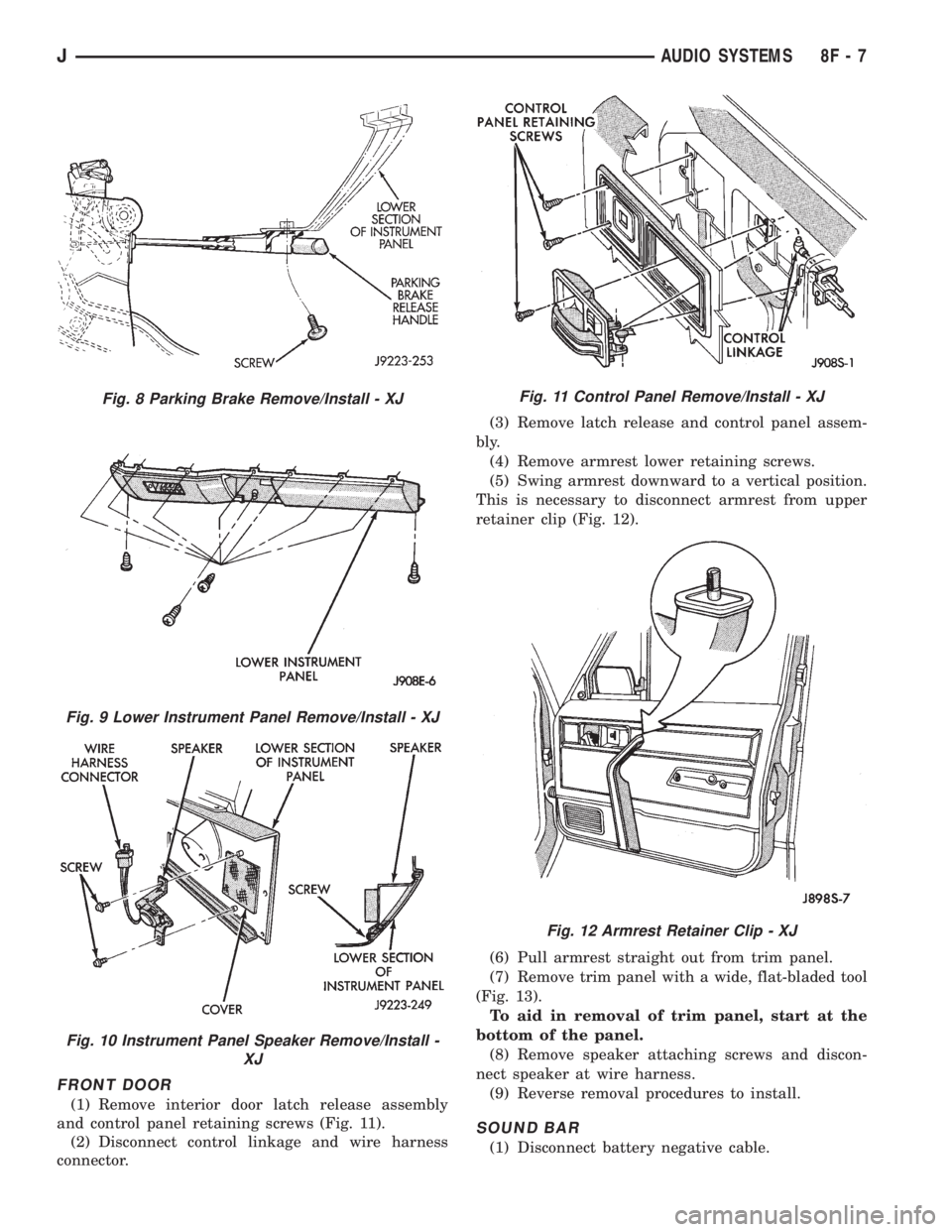
(1) Remove parking brake retaining screw from
lower instrument panel (Fig. 8).
(2) Remove retaining screws and the lower instru-
ment panel (Fig. 9).
(3) Unplug wire harness connector.
(4) Remove speaker screws and speaker from lower
instrument panel (Fig. 10).
(5) Reverse removal procedures to install.
Fig. 4 Instrument Bezel Remove/Install - XJ
Fig. 5 Radio Mounting Screws Remove/Install - XJ
Fig. 6 Radio Wiring Remove/Install - XJ
Fig. 7 Radio Clip Install - XJ
8F - 6 AUDIO SYSTEMSJ
Page 407 of 2158
FRONT DOOR
(1) Remove interior door latch release assembly
and control panel retaining screws (Fig. 11).
(2) Disconnect control linkage and wire harness
connector.(3) Remove latch release and control panel assem-
bly.
(4) Remove armrest lower retaining screws.
(5) Swing armrest downward to a vertical position.
This is necessary to disconnect armrest from upper
retainer clip (Fig. 12).
(6) Pull armrest straight out from trim panel.
(7) Remove trim panel with a wide, flat-bladed tool
(Fig. 13).
To aid in removal of trim panel, start at the
bottom of the panel.
(8) Remove speaker attaching screws and discon-
nect speaker at wire harness.
(9) Reverse removal procedures to install.
SOUND BAR
(1) Disconnect battery negative cable.
Fig. 8 Parking Brake Remove/Install - XJ
Fig. 9 Lower Instrument Panel Remove/Install - XJ
Fig. 10 Instrument Panel Speaker Remove/Install -
XJ
Fig. 11 Control Panel Remove/Install - XJ
Fig. 12 Armrest Retainer Clip - XJ
JAUDIO SYSTEMS 8F - 7
Page 409 of 2158
(9) Apply a rubberized undercoating material to
the splash panel screws.
RADIO REMOVE/INSTALL - YJ
(1) Disconnect battery negative cable.
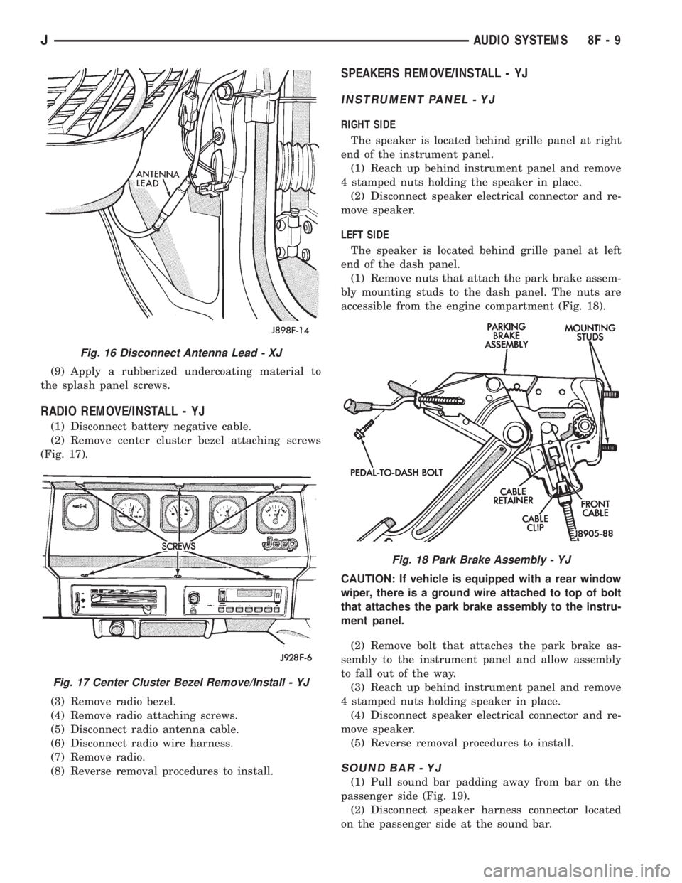
(2) Remove center cluster bezel attaching screws
(Fig. 17).
(3) Remove radio bezel.
(4) Remove radio attaching screws.
(5) Disconnect radio antenna cable.
(6) Disconnect radio wire harness.
(7) Remove radio.
(8) Reverse removal procedures to install.
SPEAKERS REMOVE/INSTALL - YJ
INSTRUMENT PANEL - YJ
RIGHT SIDE
The speaker is located behind grille panel at right
end of the instrument panel.
(1) Reach up behind instrument panel and remove
4 stamped nuts holding the speaker in place.
(2) Disconnect speaker electrical connector and re-
move speaker.
LEFT SIDE
The speaker is located behind grille panel at left
end of the dash panel.
(1) Remove nuts that attach the park brake assem-
bly mounting studs to the dash panel. The nuts are
accessible from the engine compartment (Fig. 18).
CAUTION: If vehicle is equipped with a rear window
wiper, there is a ground wire attached to top of bolt
that attaches the park brake assembly to the instru-
ment panel.
(2) Remove bolt that attaches the park brake as-
sembly to the instrument panel and allow assembly
to fall out of the way.
(3) Reach up behind instrument panel and remove
4 stamped nuts holding speaker in place.
(4) Disconnect speaker electrical connector and re-
move speaker.
(5) Reverse removal procedures to install.
SOUND BAR - YJ
(1) Pull sound bar padding away from bar on the
passenger side (Fig. 19).
(2) Disconnect speaker harness connector located
on the passenger side at the sound bar.
Fig. 16 Disconnect Antenna Lead - XJ
Fig. 17 Center Cluster Bezel Remove/Install - YJ
Fig. 18 Park Brake Assembly - YJ
JAUDIO SYSTEMS 8F - 9
Page 410 of 2158
(3) Remove screws holding speaker grille and
speaker to bar.
(4) Disconnect wires from speaker and remove
speaker.
(5) Reverse removal procedures to install.
SOUND BAR REMOVE/INSTALL - YJ
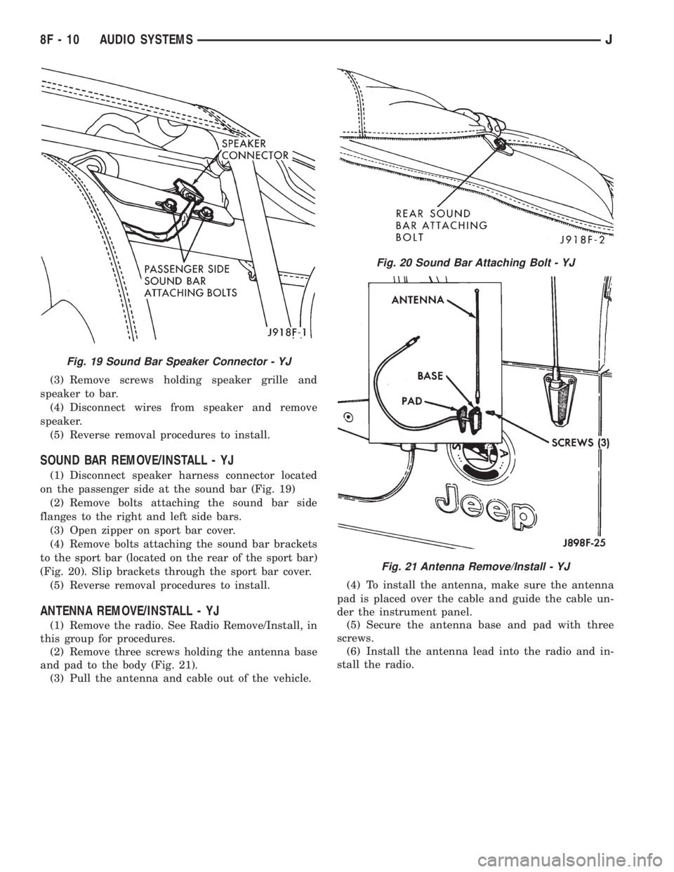
(1) Disconnect speaker harness connector located
on the passenger side at the sound bar (Fig. 19)
(2) Remove bolts attaching the sound bar side
flanges to the right and left side bars.
(3) Open zipper on sport bar cover.
(4) Remove bolts attaching the sound bar brackets
to the sport bar (located on the rear of the sport bar)
(Fig. 20). Slip brackets through the sport bar cover.
(5) Reverse removal procedures to install.
ANTENNA REMOVE/INSTALL - YJ
(1) Remove the radio. See Radio Remove/Install, in
this group for procedures.
(2) Remove three screws holding the antenna base
and pad to the body (Fig. 21).
(3) Pull the antenna and cable out of the vehicle.(4) To install the antenna, make sure the antenna
pad is placed over the cable and guide the cable un-
der the instrument panel.
(5) Secure the antenna base and pad with three
screws.
(6) Install the antenna lead into the radio and in-
stall the radio.
Fig. 19 Sound Bar Speaker Connector - YJ
Fig. 20 Sound Bar Attaching Bolt - YJ
Fig. 21 Antenna Remove/Install - YJ
8F - 10 AUDIO SYSTEMSJ
Page 411 of 2158

HORNS
CONTENTS
page page
DIAGNOSIS............................. 2
GENERAL INFORMATION.................. 1SERVICE PROCEDURES................... 3
SPECIFICATIONS......................... 5
GENERAL INFORMATION
Following are general descriptions of the major
components in the XJ (Cherokee)/YJ (Wrangler) horn
systems. Refer to Group 8W - Wiring Diagrams for
complete circuit descriptions and diagrams.
HORN SWITCH
XJ
Two horn switches are installed in the steering
wheel, one on each side of the center-mounted driv-
er's airbag module. When either switch is depressed
it completes a circuit to ground for the coil side of the
horn relay. The steering wheel and steering column
must be properly grounded for the horn switches to
function. The horn switches are only serviced as a set
with their wiring. If either switch should fail, both
switches must be replaced.
YJ
A single switch is installed in the center of the
steering wheel, directly under the horn button. When
the horn button is depressed the switch completes a
circuit to ground for the coil side of the horn relay.
The steering wheel and steering column must be
properly grounded for the horn switch to function.
The horn switch is available for service.
HORN RELAY
On XJ models, the horn relay is a mini-relay in-
stalled in the relay center, which is mounted to the
lower instrument panel reinforcement inboard of thesteering column. On YJ models, the horn relay is a
ISO relay installed in the Power Distribution Center
(PDC) near the battery tray. Refer to underside of
PDC cover for relay identification.
One side of the horn relay electromagnetic coil re-
ceives battery voltage at all times. When a horn
switch is depressed, the other side of the relay coil is
grounded. The energized relay coil causes the nor-
mally open relay contacts to close, providing battery
voltage to the horn.
If a problem is encountered with a continuously
sounding horn, it can usually be quickly resolved by
removing the horn relay until further diagnosis is
completed.
HORNS
On YJ models, a standard single, low-note, dia-
phragm-type horn is mounted and grounded to the
left inner fender shield under the hood. Dual horns
are standard equipment on XJ models. The high-note
diaphragm-type horn is mounted and grounded to
the left radiator closure panel brace behind the front
bumper. The low-note diaphragm-type horn is con-
nected in parallel with the high-note horn and is
mounted and grounded to the right radiator closure
panel brace behind the front bumper.
On XJ models, a cadmium-plated screw is
used to attach the horns to the body. Do not
substitute other types of screws as they may be-
come corroded and cause a loss of ground.
JHORNS 8G - 1
Page 417 of 2158

VEHICLE SPEED CONTROL SYSTEM
CONTENTS
page page
DIAGNOSIS............................. 2
GENERAL INFORMATION.................. 1SERVICE PROCEDURES................... 9
GENERAL INFORMATION
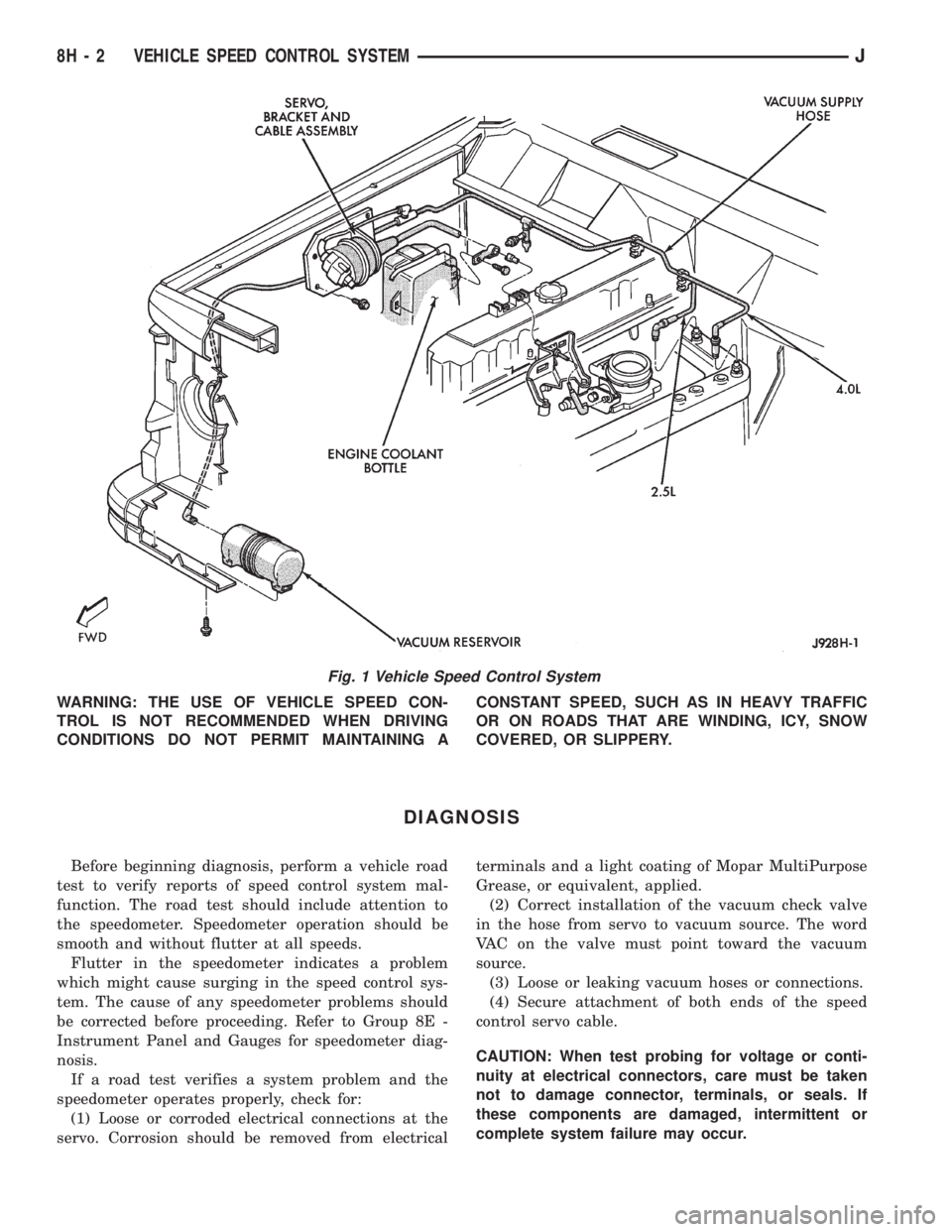
The vehicle speed control system (Fig. 1) is an
available option on all XJ (Cherokee) models. The
system is electronically controlled and vacuum oper-
ated. Following are general descriptions of the major
components in the vehicle speed control system. Re-
fer to Group 8W - Wiring Diagrams for complete cir-
cuit descriptions and diagrams.
SPEED CONTROL SERVO
The speed control servo is mounted to a bracket on
the right side inner fender shield in the engine com-
partment. The servo unit consists of a solenoid valve
body, a vacuum servo and the mounting bracket. The
PCM controls the solenoid valve body. The solenoid
valve body controls the application and release of
vacuum to the diaphragm of the vacuum servo. The
servo unit cannot be repaired and is serviced only as
a complete assembly.
SPEED CONTROL SWITCH
The speed control switch module is mounted to the
center of the steering wheel below the driver's airbag
module. The PCM monitors the state of the speed
control switches. The individual switches are labeled:
OFF/ON, RESUME/ACCEL, SET/COAST. Refer to
the owner's manual for more information on speed
control switch functions and setting procedures. The
individual switches cannot be repaired. If one switch
fails, the entire switch module must be replaced.
STOP LAMP SWITCH
Vehicles with the speed control option use a dual
function stop lamp switch. The switch is mounted in
the same location as the conventional stop lamp
switch, on the brake pedal mounting bracket under
the instrument panel. The PCM monitors the state of
the dual function stop lamp switch. Refer to Group 5
- Brakes for more information on stop lamp switch
service and adjustment procedures.
SERVO CABLE
The speed control servo cable is connected betweenthe speed control vacuum servo diaphragm and the
throttle control linkage. This cable causes the throt-
tle control linkage to open or close the throttle valve
in response to movement of the vacuum servo dia-
phragm.
POWERTRAIN CONTROL MODULE
The speed control electronic control circuitry is in-
tegrated into the Powertrain Control Module (PCM).
The PCM is located in the engine compartment on
the left side inner fender shield. The PCM speed con-
trol functions are monitored by the On-Board Diag-
nostics (OBD). All OBD-sensed systems are
monitored by the PCM. Each monitored circuit is as-
signed a Diagnostic Trouble Code (DTC). The PCM
will store a DTC in electronic memory for any failure
it detects. See Using On-Board Diagnostic System in
this group for more information. The PCM cannot be
repaired and must be replaced if faulty.
VACUUM RESERVOIR
The vacuum reservoir is mounted behind the left
end of the front bumper bar. The reservoir contains a
one-way check valve to trap engine vacuum in the
reservoir. When engine vacuum drops, as in climbing
a grade while driving, the reservoir supplies the vac-
uum needed to maintain proper speed control opera-
tion. The vacuum reservoir cannot be repaired and
must be replaced if faulty.
VEHICLE SPEED SENSOR
The Vehicle Speed Sensor (VSS) is a pulse genera-
tor mounted to an adapter near the transmission
(two-wheel drive) or transfer case (four-wheel drive)
output shaft. The sensor is driven through the
adapter by a speedometer pinion gear. The VSS pulse
signal to the speedometer/odometer is monitored by
the PCM speed control circuitry to determine vehicle
speed and to maintain speed control set speed. Refer
to the appropriate Powertrain Diagnostic Procedures
manual for testing of this component. Refer to Group
14 - Fuel System for service of this component.
JVEHICLE SPEED CONTROL SYSTEM 8H - 1
Page 418 of 2158
WARNING: THE USE OF VEHICLE SPEED CON-
TROL IS NOT RECOMMENDED WHEN DRIVING
CONDITIONS DO NOT PERMIT MAINTAINING ACONSTANT SPEED, SUCH AS IN HEAVY TRAFFIC
OR ON ROADS THAT ARE WINDING, ICY, SNOW
COVERED, OR SLIPPERY.
DIAGNOSIS
Before beginning diagnosis, perform a vehicle road
test to verify reports of speed control system mal-
function. The road test should include attention to
the speedometer. Speedometer operation should be
smooth and without flutter at all speeds.
Flutter in the speedometer indicates a problem
which might cause surging in the speed control sys-
tem. The cause of any speedometer problems should
be corrected before proceeding. Refer to Group 8E -
Instrument Panel and Gauges for speedometer diag-
nosis.
If a road test verifies a system problem and the
speedometer operates properly, check for:
(1) Loose or corroded electrical connections at the
servo. Corrosion should be removed from electricalterminals and a light coating of Mopar MultiPurpose
Grease, or equivalent, applied.
(2) Correct installation of the vacuum check valve
in the hose from servo to vacuum source. The word
VAC on the valve must point toward the vacuum
source.
(3) Loose or leaking vacuum hoses or connections.
(4) Secure attachment of both ends of the speed
control servo cable.
CAUTION: When test probing for voltage or conti-
nuity at electrical connectors, care must be taken
not to damage connector, terminals, or seals. If
these components are damaged, intermittent or
complete system failure may occur.
Fig. 1 Vehicle Speed Control System
8H - 2 VEHICLE SPEED CONTROL SYSTEMJ