1995 JEEP YJ instrument panel
[x] Cancel search: instrument panelPage 441 of 2158
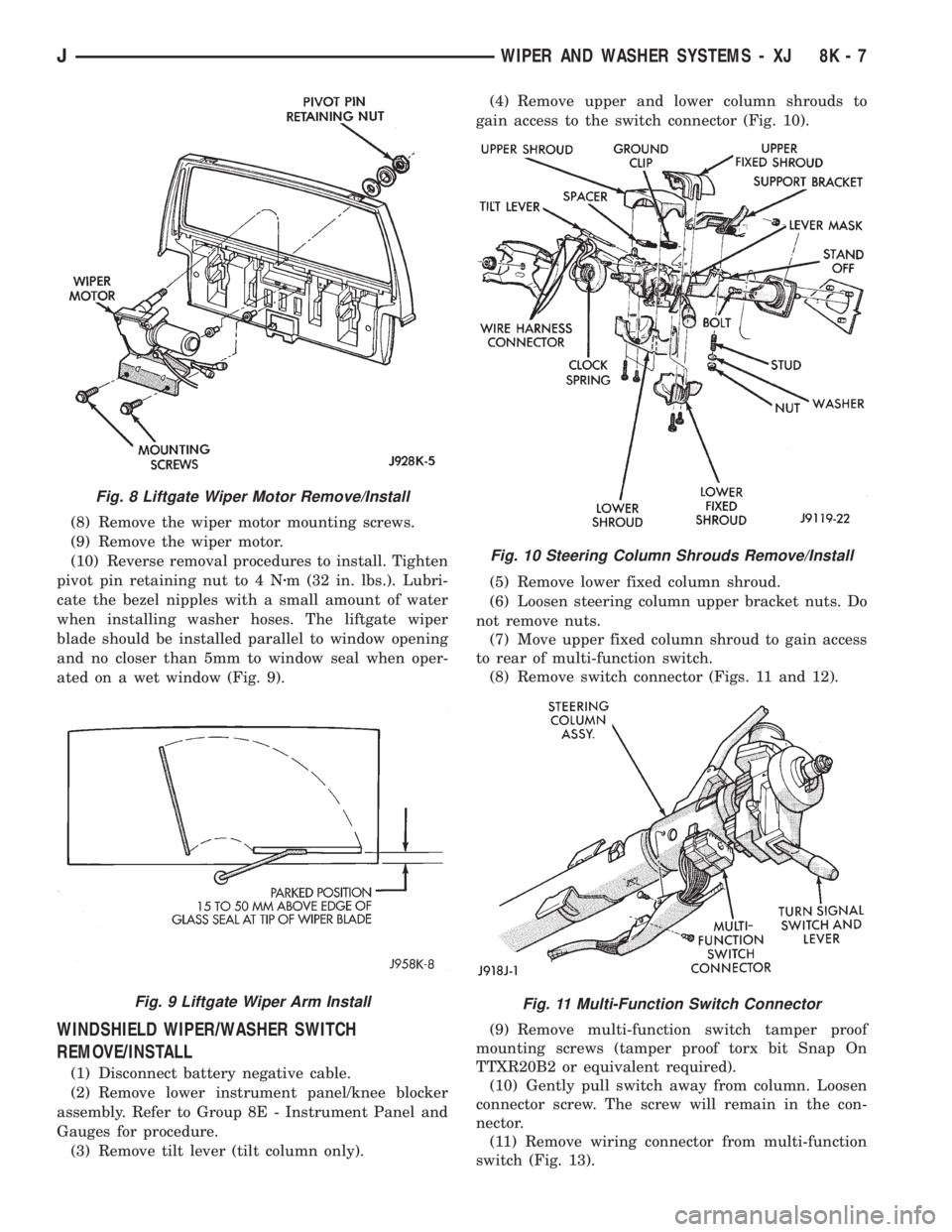
(8) Remove the wiper motor mounting screws.
(9) Remove the wiper motor.
(10) Reverse removal procedures to install. Tighten
pivot pin retaining nut to 4 Nzm (32 in. lbs.). Lubri-
cate the bezel nipples with a small amount of water
when installing washer hoses. The liftgate wiper
blade should be installed parallel to window opening
and no closer than 5mm to window seal when oper-
ated on a wet window (Fig. 9).
WINDSHIELD WIPER/WASHER SWITCH
REMOVE/INSTALL
(1) Disconnect battery negative cable.
(2) Remove lower instrument panel/knee blocker
assembly. Refer to Group 8E - Instrument Panel and
Gauges for procedure.
(3) Remove tilt lever (tilt column only).(4) Remove upper and lower column shrouds to
gain access to the switch connector (Fig. 10).
(5) Remove lower fixed column shroud.
(6) Loosen steering column upper bracket nuts. Do
not remove nuts.
(7) Move upper fixed column shroud to gain access
to rear of multi-function switch.
(8) Remove switch connector (Figs. 11 and 12).
(9) Remove multi-function switch tamper proof
mounting screws (tamper proof torx bit Snap On
TTXR20B2 or equivalent required).
(10) Gently pull switch away from column. Loosen
connector screw. The screw will remain in the con-
nector.
(11) Remove wiring connector from multi-function
switch (Fig. 13).
Fig. 8 Liftgate Wiper Motor Remove/Install
Fig. 9 Liftgate Wiper Arm Install
Fig. 10 Steering Column Shrouds Remove/Install
Fig. 11 Multi-Function Switch Connector
JWIPER AND WASHER SYSTEMS - XJ 8K - 7
Page 442 of 2158
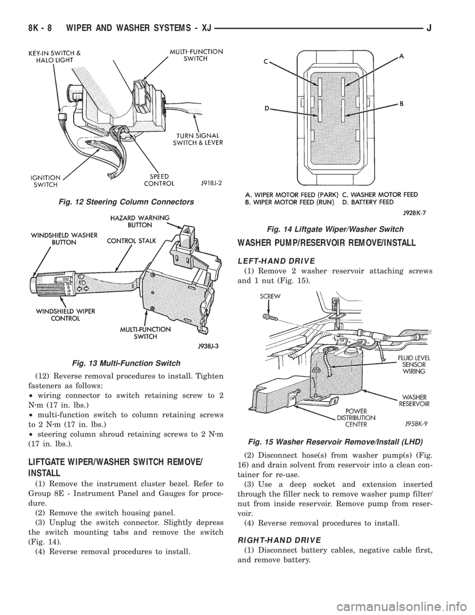
(12) Reverse removal procedures to install. Tighten
fasteners as follows:
²wiring connector to switch retaining screw to 2
Nzm (17 in. lbs.)
²multi-function switch to column retaining screws
to2Nzm (17 in. lbs.)
²steering column shroud retaining screws to 2 Nzm
(17 in. lbs.).
LIFTGATE WIPER/WASHER SWITCH REMOVE/
INSTALL
(1) Remove the instrument cluster bezel. Refer to
Group 8E - Instrument Panel and Gauges for proce-
dure.
(2) Remove the switch housing panel.
(3) Unplug the switch connector. Slightly depress
the switch mounting tabs and remove the switch
(Fig. 14).
(4) Reverse removal procedures to install.
WASHER PUMP/RESERVOIR REMOVE/INSTALL
LEFT-HAND DRIVE
(1) Remove 2 washer reservoir attaching screws
and 1 nut (Fig. 15).
(2) Disconnect hose(s) from washer pump(s) (Fig.
16) and drain solvent from reservoir into a clean con-
tainer for re-use.
(3) Use a deep socket and extension inserted
through the filler neck to remove washer pump filter/
nut from inside reservoir. Remove pump from reser-
voir.
(4) Reverse removal procedures to install.
RIGHT-HAND DRIVE
(1) Disconnect battery cables, negative cable first,
and remove battery.
Fig. 12 Steering Column Connectors
Fig. 13 Multi-Function Switch
Fig. 14 Liftgate Wiper/Washer Switch
Fig. 15 Washer Reservoir Remove/Install (LHD)
8K - 8 WIPER AND WASHER SYSTEMS - XJJ
Page 444 of 2158

GENERAL INFORMATION - YJ
Following are general descriptions of the major
components in the YJ (Wrangler) wiper and washer
systems. Refer to Group 8W - Wiring Diagrams for
complete circuit descriptions and diagrams.
WINDSHIELD WIPER SYSTEM
A two-speed wiper system is standard equipment
on all YJ models. An optional intermittent wipe sys-
tem is available. The standard system allows the
driver to select from two wiper speeds. The optional
intermittent wipe system allows the driver to select
from two wiper speeds or an intermittent wipe fea-
ture that allows a delay between wipes of 2 to 15 sec-
onds. Refer to the owner's manual for more
information on wiper system controls and operation.
The wipers will operate only when the ignition
switch is in the ACCESSORY or ON position. A cir-
cuit breaker in the fuseblock module protects the cir-
cuitry of the wiper system.
WINDSHIELD WASHER SYSTEM
A electrically-operated windshield washer system is
standard equipment on all YJ models. The washers
will operate only when the ignition switch is in the
ACCESSORY or ON position. A circuit breaker in the
fuseblock module protects the circuitry of the washer
system. Refer to the owner's manual for more infor-
mation on washer system controls and operation.
LIFTGATE WIPER/WASHER SYSTEM
A liftgate wiper/washer system is an available op-
tion on YJ models equipped with the optional hard-
top. The liftgate wiper is a fixed cycle wipe system. A
single switch on the instrument panel controls both
the liftgate wiper and washer functions. These sys-
tems will operate only when the ignition switch is in
the ON position. Fuse 1 in the fuseblock module pro-
tects the circuitry of both the liftgate wiper and
washer. Refer to the owner's manual for more infor-
mation on liftgate wiper/washer system controls and
operation.
WIPER ARMS, BLADES, AND ELEMENTS
All YJ models have two 12-inch windshield wiper
blades with replaceable rubber elements (squeegees).
Models with the liftgate wiper option use a single 16-
inch wiper blade with a replaceable rubber element
(squeegee).
Caution should be exercised to protect the rubber
squeegees from any petroleum-based cleaners or con-
taminants, which will rapidly deteriorate the squee-
gee rubber. If squeegees are damaged, worn or
contaminated they must be replaced.
Wiper squeegees exposed to the weather for a long
time tend to lose their wiping effectiveness. Periodiccleaning of the squeegees is suggested to remove de-
posits of salt and road film. The wiper blades, arms
and windshield or liftgate glass should be cleaned
with a sponge or cloth and a mild detergent or non-
abrasive cleaner. If the squeegees continue to streak
or smear, they should be replaced.
The blades are mounted to spring-loaded wiper
arms. Spring tension of the wiper arms controls the
pressure applied to the blades on the glass. The
windshield wiper arms are attached by an integral
latch to the two wiper pivots on the windshield frame
at the base of the windshield. The liftgate wiper arm
is attached by an integral latch directly to the lift-
gate wiper motor output shaft on the liftgate glass.
The wiper arms and blades can not be adjusted or re-
paired. If faulty, they must be replaced.
WIPER LINKAGE AND PIVOTS
The wiper pivots are fastened to the windshield
frame with nuts. The pivots and linkage are serviced
through access holes in the interior side of the lower
windshield frame. The two pivots and their connect-
ing link are serviced as a unit. The drive link, which
connects the motor crank arm to the left pivot, is ser-
viced separately.
WINDSHIELD WIPER MOTOR
The two-speed permanent magnet wiper motor has
an integral transmission and park switch. The motor
is mounted to a cover plate on the interior side of the
lower windshield frame. The wiper motor output
shaft passes through a gasket and the cover plate
into the space between the inner and outer lower
windshield frame, where the crank arm attached to
the output shaft drives the wiper drive link.
Wiper speed is controlled by current flow to the ap-
propriate set of brushes. The wiper motor completes
its wipe cycle when the switch is turned OFF, and
parks the blades in the lowest portion of the wipe
pattern. The wiper motor assembly can not be re-
paired. If faulty, the entire motor assembly must be
replaced. The cover plate, gasket and drive link to
crank arm retaining ring are available for service.
LIFTGATE WIPER MOTOR
The liftgate wiper motor operates in three modes:
²constant wipe that operates when the liftgate
wiper/washer switch is placed in the Wipe position
²constant wipe that operates when the liftgate
washers are operated
²a park mode that runs the motor until the wiper
blade reaches the park position after the liftgate
wiper switch or ignition switch is turned OFF.
8K - 10 WIPER AND WASHER SYSTEMS - YJJ
Page 445 of 2158
The liftgate wiper motor can not be repaired. If
faulty, the entire assembly must be replaced.
WINDSHIELD WIPER/WASHER SWITCH
Controls for the windshield wiper and washer sys-
tems are contained in the turn signal switch lever.
The turn signal switch lever is mounted on the left
side of the steering column between the steering
wheel and the instrument panel. The wiper/washer
switch can not be repaired. If any function of the
switch is faulty, the entire switch must be replaced.
LIFTGATE WIPER/WASHER SWITCH
The single two-function switch on the instrument
panel right of the steering column controls the lift-
gate wiper and washer functions. The rocker-type
switch features a detent in the WIPE position, but
only momentary contact in the WASH position. Both
the liftgate wiper and liftgate washer motors will op-
erate continuously for as long as the switch is held in
the WASH position. The switch can not be repaired;
if faulty, it must be replaced.
INTERMITTENT WIPE MODULE
In addition to low and high speed, the optional in-
termittent wipe system has a delay mode. The delay
mode has a range of 2 to 15 seconds. The length of
the delay is selected with a variable resistor in the
wiper switch and is accomplished by electronic cir-
cuitry within the intermittent wipe module. If the
washer knob is depressed while the wiper switch is
in the OFF position, the intermittent wipe module
will operate the wiper motor for approximately 2
wipes and automatically turn the motor off.
The intermittent wipe module is mounted to a
bracket behind the lower instrument panel, near the
steering column with a hook and loop fastener patch.
The module can not be repaired.
WINDSHIELD WASHER NOZZLES
The two fluidic washer nozzles are screwed into
openings in the cowl panel below the windshield and
are not adjustable. Washer fluid is fed to the nozzles
through hoses underneath the cowl panel. The noz-
zles can not be repaired and, if faulty, should be re-
placed.
LIFTGATE WASHER NOZZLE
The single liftgate washer nozzle is installed
through the liftgate glass and secured with a nut on
the inside of the glass. Washer fluid is fed to the noz-
zle from the washer reservoir in the engine compart-
ment. A liftgate washer hose system is routed
through the body of the vehicle with the body wiring
harness from the reservoir to the liftgate. The nozzle
can not be repaired and, if faulty, should be replaced.
WASHER RESERVOIR
The washer solvent reservoir is mounted with a
bracket to the left front inner fender shield near the
cowl panel. The same reservoir is used for both the
standard front and optional liftgate washer systems.
The reservoir and filler cap are available for service.
WASHER PUMPS
The washer pump and motor are press-fit into a
rubber grommet near the bottom of the washer res-
ervoir. Vehicles with the optional liftgate wiper/
washer system have two pumps installed in the
single reservoir. A permanently lubricated and sealed
motor is coupled to a rotor-type pump. Washer fluid
is gravity fed from the reservoir to the pump. The
pump then pressurizes the fluid and forces it through
the plumbing to the nozzles when the motor is ener-
gized. The pump and motor can not be repaired. If
faulty, the entire assembly must be replaced.
JWIPER AND WASHER SYSTEMS - YJ 8K - 11
Page 452 of 2158
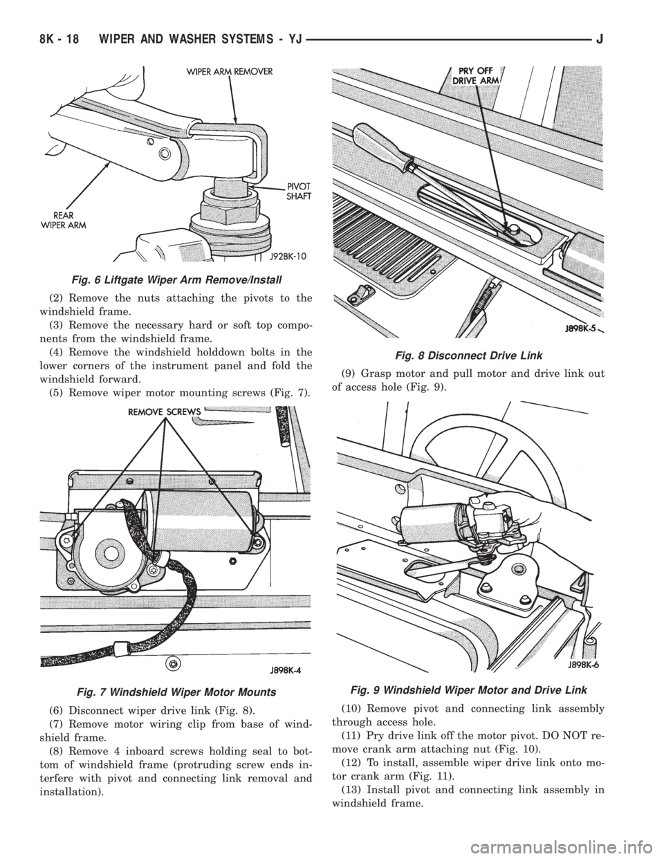
(2) Remove the nuts attaching the pivots to the
windshield frame.
(3) Remove the necessary hard or soft top compo-
nents from the windshield frame.
(4) Remove the windshield holddown bolts in the
lower corners of the instrument panel and fold the
windshield forward.
(5) Remove wiper motor mounting screws (Fig. 7).
(6) Disconnect wiper drive link (Fig. 8).
(7) Remove motor wiring clip from base of wind-
shield frame.
(8) Remove 4 inboard screws holding seal to bot-
tom of windshield frame (protruding screw ends in-
terfere with pivot and connecting link removal and
installation).(9) Grasp motor and pull motor and drive link out
of access hole (Fig. 9).
(10) Remove pivot and connecting link assembly
through access hole.
(11) Pry drive link off the motor pivot. DO NOT re-
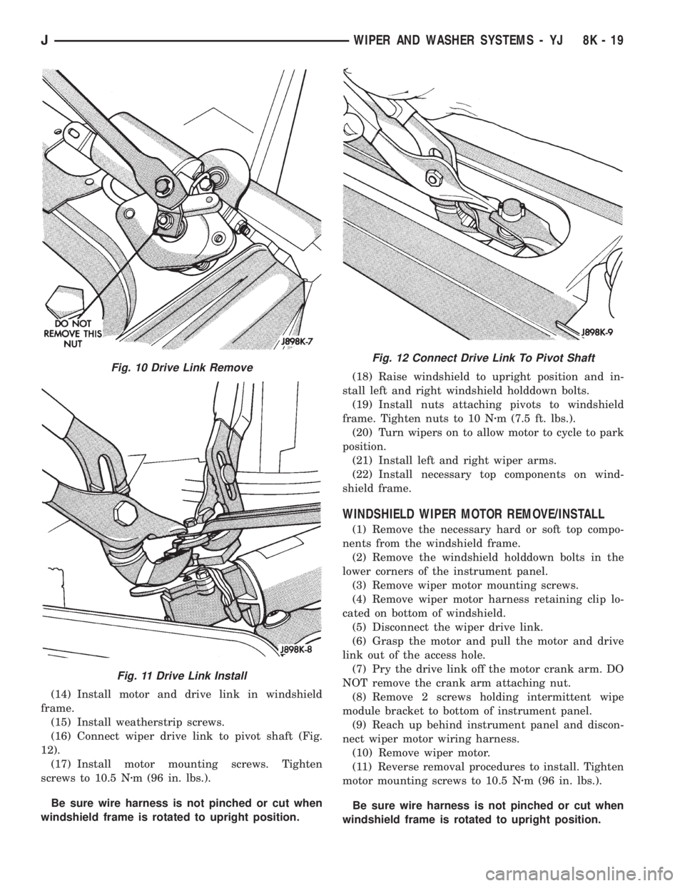
move crank arm attaching nut (Fig. 10).
(12) To install, assemble wiper drive link onto mo-
tor crank arm (Fig. 11).
(13) Install pivot and connecting link assembly in
windshield frame.
Fig. 6 Liftgate Wiper Arm Remove/Install
Fig. 7 Windshield Wiper Motor Mounts
Fig. 8 Disconnect Drive Link
Fig. 9 Windshield Wiper Motor and Drive Link
8K - 18 WIPER AND WASHER SYSTEMS - YJJ
Page 453 of 2158
(14) Install motor and drive link in windshield
frame.
(15) Install weatherstrip screws.
(16) Connect wiper drive link to pivot shaft (Fig.
12).
(17) Install motor mounting screws. Tighten
screws to 10.5 Nzm (96 in. lbs.).
Be sure wire harness is not pinched or cut when
windshield frame is rotated to upright position.(18) Raise windshield to upright position and in-
stall left and right windshield holddown bolts.
(19) Install nuts attaching pivots to windshield
frame. Tighten nuts to 10 Nzm (7.5 ft. lbs.).
(20) Turn wipers on to allow motor to cycle to park
position.
(21) Install left and right wiper arms.
(22) Install necessary top components on wind-
shield frame.
WINDSHIELD WIPER MOTOR REMOVE/INSTALL
(1) Remove the necessary hard or soft top compo-
nents from the windshield frame.
(2) Remove the windshield holddown bolts in the
lower corners of the instrument panel.
(3) Remove wiper motor mounting screws.
(4) Remove wiper motor harness retaining clip lo-
cated on bottom of windshield.
(5) Disconnect the wiper drive link.
(6) Grasp the motor and pull the motor and drive
link out of the access hole.
(7) Pry the drive link off the motor crank arm. DO
NOT remove the crank arm attaching nut.
(8) Remove 2 screws holding intermittent wipe
module bracket to bottom of instrument panel.
(9) Reach up behind instrument panel and discon-
nect wiper motor wiring harness.
(10) Remove wiper motor.
(11) Reverse removal procedures to install. Tighten
motor mounting screws to 10.5 Nzm (96 in. lbs.).
Be sure wire harness is not pinched or cut when
windshield frame is rotated to upright position.
Fig. 10 Drive Link Remove
Fig. 11 Drive Link Install
Fig. 12 Connect Drive Link To Pivot Shaft
JWIPER AND WASHER SYSTEMS - YJ 8K - 19
Page 458 of 2158
(36) Install a new switch and switch cover.
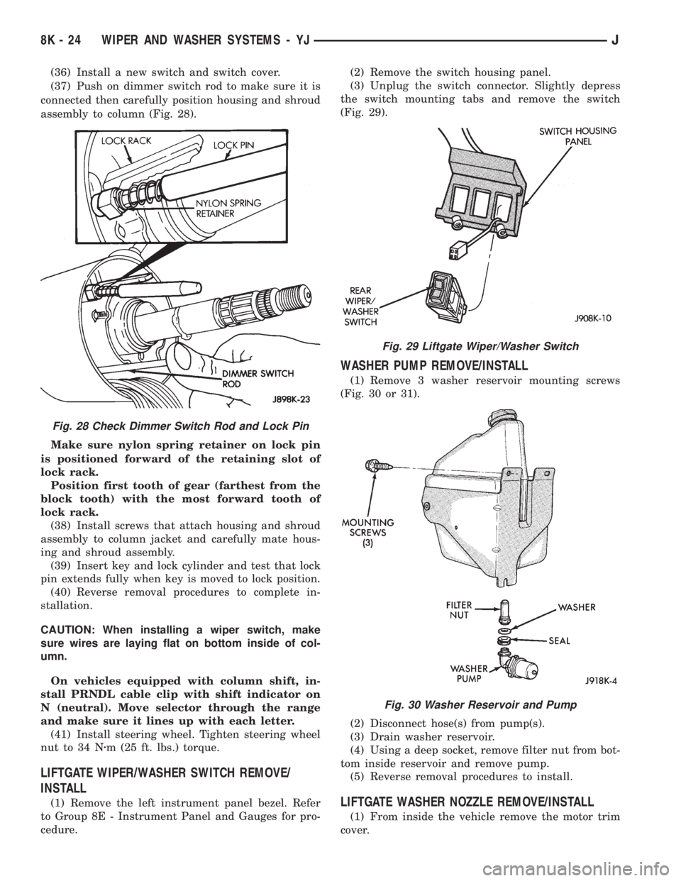
(37) Push on dimmer switch rod to make sure it is
connected then carefully position housing and shroud
assembly to column (Fig. 28).
Make sure nylon spring retainer on lock pin
is positioned forward of the retaining slot of
lock rack.
Position first tooth of gear (farthest from the
block tooth) with the most forward tooth of
lock rack.
(38) Install screws that attach housing and shroud
assembly to column jacket and carefully mate hous-
ing and shroud assembly.
(39) Insert key and lock cylinder and test that lock
pin extends fully when key is moved to lock position.
(40) Reverse removal procedures to complete in-
stallation.
CAUTION: When installing a wiper switch, make
sure wires are laying flat on bottom inside of col-
umn.
On vehicles equipped with column shift, in-
stall PRNDL cable clip with shift indicator on
N (neutral). Move selector through the range
and make sure it lines up with each letter.
(41) Install steering wheel. Tighten steering wheel
nut to 34 Nzm (25 ft. lbs.) torque.
LIFTGATE WIPER/WASHER SWITCH REMOVE/
INSTALL
(1) Remove the left instrument panel bezel. Refer
to Group 8E - Instrument Panel and Gauges for pro-
cedure.(2) Remove the switch housing panel.
(3) Unplug the switch connector. Slightly depress
the switch mounting tabs and remove the switch
(Fig. 29).
WASHER PUMP REMOVE/INSTALL
(1) Remove 3 washer reservoir mounting screws
(Fig. 30 or 31).
(2) Disconnect hose(s) from pump(s).
(3) Drain washer reservoir.
(4) Using a deep socket, remove filter nut from bot-
tom inside reservoir and remove pump.
(5) Reverse removal procedures to install.
LIFTGATE WASHER NOZZLE REMOVE/INSTALL
(1) From inside the vehicle remove the motor trim
cover.
Fig. 28 Check Dimmer Switch Rod and Lock Pin
Fig. 29 Liftgate Wiper/Washer Switch
Fig. 30 Washer Reservoir and Pump
8K - 24 WIPER AND WASHER SYSTEMS - YJJ
Page 464 of 2158
MULTI-FUNCTION SWITCH TESTING
PROCEDURESÐXJ
The multi-function switch contains electrical cir-
cuitry for:
²Headlamp Dimmer Switch.
²Passing Lights.
²Turn Signals.
²Hazard Warning.
²Windshield Wiper.
²Pulse Wiper.
²Windshield Washer.
This integrated switch is mounted to the left hand
side of the steering column. Should any function of
the switch fail, the entire switch must be replaced.
The multi-function switch also serves as a fog lamp
lock-out circuit. The circuit to the fog lamp switch is
completed only when the dimmer switch is in the low
beam position.
SWITCH TEST
(1) Disconnect battery negative cable.
(2) Remove lower instrument panel screws along
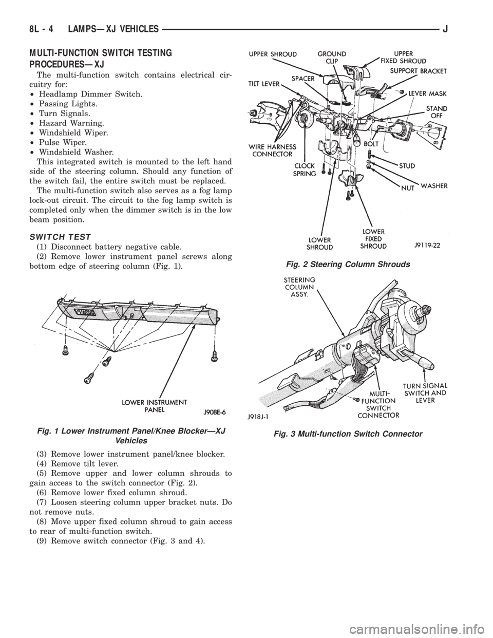
bottom edge of steering column (Fig. 1).
(3) Remove lower instrument panel/knee blocker.
(4) Remove tilt lever.
(5) Remove upper and lower column shrouds to
gain access to the switch connector (Fig. 2).
(6) Remove lower fixed column shroud.
(7) Loosen steering column upper bracket nuts. Do
not remove nuts.
(8) Move upper fixed column shroud to gain access
to rear of multi-function switch.
(9) Remove switch connector (Fig. 3 and 4).
Fig. 1 Lower Instrument Panel/Knee BlockerÐXJ
Vehicles
Fig. 2 Steering Column Shrouds
Fig. 3 Multi-function Switch Connector
8L - 4 LAMPSÐXJ VEHICLESJ