1995 JEEP YJ cooling
[x] Cancel search: coolingPage 2084 of 2158
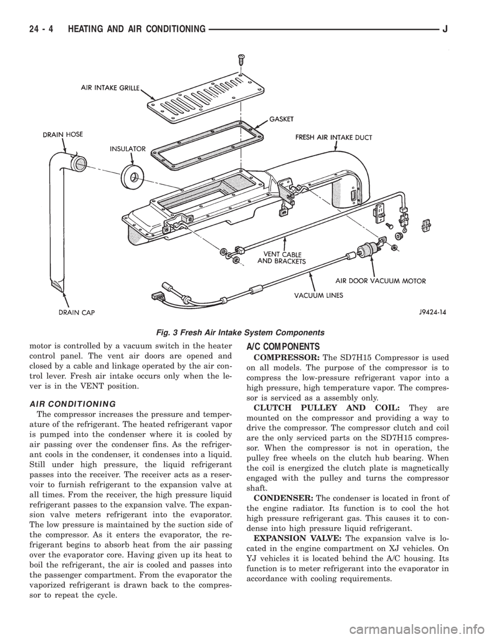
motor is controlled by a vacuum switch in the heater
control panel. The vent air doors are opened and
closed by a cable and linkage operated by the air con-
trol lever. Fresh air intake occurs only when the le-
ver is in the VENT position.
AIR CONDITIONING
The compressor increases the pressure and temper-
ature of the refrigerant. The heated refrigerant vapor
is pumped into the condenser where it is cooled by
air passing over the condenser fins. As the refriger-
ant cools in the condenser, it condenses into a liquid.
Still under high pressure, the liquid refrigerant
passes into the receiver. The receiver acts as a reser-
voir to furnish refrigerant to the expansion valve at
all times. From the receiver, the high pressure liquid
refrigerant passes to the expansion valve. The expan-
sion valve meters refrigerant into the evaporator.
The low pressure is maintained by the suction side of
the compressor. As it enters the evaporator, the re-
frigerant begins to absorb heat from the air passing
over the evaporator core. Having given up its heat to
boil the refrigerant, the air is cooled and passes into
the passenger compartment. From the evaporator the
vaporized refrigerant is drawn back to the compres-
sor to repeat the cycle.
A/C COMPONENTS
COMPRESSOR:The SD7H15 Compressor is used
on all models. The purpose of the compressor is to
compress the low-pressure refrigerant vapor into a
high pressure, high temperature vapor. The compres-
sor is serviced as a assembly only.
CLUTCH PULLEY AND COIL:They are
mounted on the compressor and providing a way to
drive the compressor. The compressor clutch and coil
are the only serviced parts on the SD7H15 compres-
sor. When the compressor is not in operation, the
pulley free wheels on the clutch hub bearing. When
the coil is energized the clutch plate is magnetically
engaged with the pulley and turns the compressor
shaft.
CONDENSER:The condenser is located in front of
the engine radiator. Its function is to cool the hot
high pressure refrigerant gas. This causes it to con-
dense into high pressure liquid refrigerant.
EXPANSION VALVE:The expansion valve is lo-
cated in the engine compartment on XJ vehicles. On
YJ vehicles it is located behind the A/C housing. Its
function is to meter refrigerant into the evaporator in
accordance with cooling requirements.
Fig. 3 Fresh Air Intake System Components
24 - 4 HEATING AND AIR CONDITIONINGJ
Page 2090 of 2158
oil until you are ready to use it. Install the cap im-
mediately after using. Store the oil only in a clean
moisture-free container.
Keep service tools and the work area clean. Con-
tamination of A/C system through careless work hab-
its must be avoided.
COOLING SYSTEM
To maintain the performance level of the heating/
air conditioning system, the engine cooling system
must be properly maintained.
The use of a bug screen is not recommended. Any
obstructions in front of the radiator or condenser can
reduce the performance of the A/C and cooling sys-
tem. If a bug screen is used it must be cleaned fre-
quently.
COOLANT PRECAUTIONS
WARNING: ANTIFREEZE IS AN ETHYLENE GLYCOL
BASE COOLANT AND IS HARMFUL IF SWAL-
LOWED OR INHALED. IF SWALLOWED, DRINK
TWO GLASSES OF WATER AND INDUCE VOMIT-
ING. IF INHALED, MOVE TO FRESH AIR AREA.
SEEK MEDICAL ATTENTION IMMEDIATELY.
WARNING: WASH SKIN AND CLOTHING THOR-
OUGHLY AFTER COMING IN CONTACT WITH ETH-
YLENE GLYCOL.
WARNING: KEEP OUT OF REACH OF CHILDREN
AND PETS.
WARNING: DO NOT OPEN A COOLING SYSTEM
WHEN THE ENGINE IS AT RUNNING TEMPERA-
TURE. PERSONAL INJURY CAN RESULT.WARNING: DO NOT STORE IN OPEN OR UN-
MARKED CONTAINERS.
WARNING: HOT ENGINE COOLANT CAN CAUSE
SEVERE BURNS. DO NOT OPEN THE RADIATOR
DRAIN COCK WHEN THE COOLING SYSTEM IS
HOT AND PRESSURIZED. ALLOW THE COOLANT
TO DECREASE TO ROOM TEMPERATURE BEFORE
STARTING REPAIR OPERATIONS.
The engine cooling system is designed to develop
internal pressure of 97 to 124 kPa (14 to 18 psi). Al-
low the vehicle 15 minutes to cool down (or until a
safe temperature and pressure are attained) before
opening the cooling system. Refer to Group 7, Cooling
System.REFRIGERANT HOSES/TUBES PRECAUTIONS
Kinks or sharp bends in the refrigerant tubing or
hoses will reduce the capacity of the entire system.
High pressures are produced in the system when it is
operating. Extreme care must be exercised to make
sure that all connections are pressure tight. Dirt and
moisture can enter the system when it is opened for
repair.
A good rule for the flexible hose lines is to keep the
radius of all bends at least 10 times the diameter of
the hose. Sharp bends will reduce the flow of refrig-
erant. The flexible hose lines should be routed so
they are at least 80 mm (3 inches) from the exhaust
manifold. It is a good practice to inspect all flexible
hose lines at least once a year to make sure they are
in good condition and properly routed.
24 - 10 HEATING AND AIR CONDITIONINGJ
Page 2091 of 2158
REFRIGERANT SERVICE AND PERFORMANCE TEST
INDEX
page page
Air Conditioning Performance Tests............ 12
Charging Refrigerant System................. 11
Evacuating Refrigerant System............... 11Leak Testing Refrigerant.................... 11
Recovering Refrigerant System............... 11
Refrigerant Oil........................... 12
LEAK TESTING REFRIGERANT
REVIEW WARNINGS AND CAUTIONS IN
THIS GROUP BEFORE LEAK TESTING.
If A/C system is not cooling properly, determine if
system is fully charged. Refer to Refrigerant System
Diagnosis Chart. If the system is empty evacuate the
A/C system and charge system with 0.283 kPa (0.6
lbs. or 10 oz.) R-134a refrigerant. Refer to Charging
Refrigerant System for instructions. To detect a leak
in the system, perform the following procedures.
(1) Position the vehicle in a wind free work area.
This will aid in detecting small leaks.
(2) Bring A/C system up to operating temperature
and pressure. This is done by allowing the engine to
run with the A/C on for 5 to 7 minutes.
(3) Open hood 5 minutes prior to leak test. This
will dissipate any accumulated refrigerant in the en-
gine compartment.
(4) With the engine not running, use an R-134a
Electronic Leak Detector and search for leaks. Move
probe slowly along the bottom side of lines and fit-
tings, because R-134a is heavier than air. Fittings,
lines, or components that appear to be oily usually
indicates a refrigerant leak.
(5) To inspect the evaporator core for leaks. Set the
blower at low speed and the selector in PANEL and
RECIRC mode check for leaks at CENTER panel out-
lets.
RECOVERING REFRIGERANT SYSTEM
REVIEW WARNINGS AND CAUTIONS IN
GENERAL INFORMATION SECTION OF THIS
GROUP BEFORE DISCHARGING SYSTEM.
R-134a refrigerant is a hydrofluorocarbon (HFC)
that does not contain chlorine. R-134a refrigerant Re-
covery/Recycling Station that meets SAE standard
J2210 must be used to recover the refrigerant. Refer
to the operating instructions provided with the equip-
ment for proper operation.
EVACUATING REFRIGERANT SYSTEM
REVIEW WARNINGS AND CAUTIONS IN
GENERAL INFORMATION SECTION OF THIS
GROUP BEFORE EVACUATING SYSTEM.
If the A/C system has been open to the atmosphere,
it must be evacuated before the system can be
charged. Moisture and air mixed with refrigerant will
raise the compressor head pressure above acceptable
operating levels. This will reduce the performance of
the air conditioner and damage the compressor. Mois-
ture will boil at near room temperature when ex-
posed to vacuum. To evacuate the refrigerant system
use following procedure:
(1) Connect a suitable charging station and mani-
fold gauge set to the vehicle.
(2) Open the low and high side valves and start
vacuum pump. When suction gauge reads 88 kPa (26
in. Hg) vacuum or greater, close all valves and turn
off vacuum pump. If system fails to reach specified
vacuum, the system has a leak that must be cor-
rected. If system maintains the specified vacuum for
30 minutes, start the vacuum pump. Then open the
suction and discharge valves and evacuate an addi-
tional 10 minutes.
(3) Close all valves. Turn off and disconnect the
vacuum pump.
The system is now ready to be charged with refrig-
erant.
CHARGING REFRIGERANT SYSTEM
REVIEW WARNINGS AND CAUTIONS IN
GENERAL INFORMATION SECTION OF THIS
GROUP BEFORE CHARGING SYSTEM.
After the system has been tested for leaks and
evacuated, a refrigerant charge can be injected into
the system. Refer to refrigerant capacities for proper
amount of refrigerant charge. Charge the system us-
ing a Recovery/Recycling/Charging Station approved
for R-134a refrigerant. Refer to the instructions pro-
vided with the equipment for proper operation.
REFRIGERANT CHARGE CAPACITY
The R-134a system charge capacity is 0.9 kPa (32
oz.) for XJ and YJ vehicles.
JHEATING AND AIR CONDITIONING 24 - 11
Page 2092 of 2158
REFRIGERANT OIL
It is important to have the correct amount of oil in
the A/C system. This will ensure proper lubrication of
the compressor. Too little oil will result in damage to
the compressor. Too much oil will reduce the cooling
capacity of the system.
The oil used in the SD7H15 compressor is a poly-
alkylene glycol synthetic oil SP-20 PAG, wax-free re-
frigerant oil. Only refrigerant oil of the same type
should be used to service the system. Do not use any
other oil. The oil container should be kept tightly
capped until it is ready for use and then capped after
use to prevent contamination. Refrigerant oil will
quickly absorb any moisture it comes in contact with.
OIL LEVEL CHECK
It will not be necessary to check oil level in the
compressor or to add oil unless there has been an oil
loss. This may be due to a rupture or leak from a
line, shaft seal, evaporator or condenser. Oil loss at a
leak point will be evident by the presence of a wet,
shiny surface around the leak.
When an A/C system is assembled at the factory,
all components (except the compressor) are refriger-
ant oil free. After the system has been charged and
operated, the oil in the compressor is dispersed
through the system. The receiver-drier, evaporator,
condenser and compressor will retain a significant
amount of oil.
Refrigerant oil must be added when a receiver-
drier, evaporator, condenser or compressor are re-
placed. When the compressor is replaced, the oil
must be drained from the replaced compressor and
measured. Drain all the oil from the new compressor.
Add back into the new compressor the amount of oil
that was drained out of the old compressor.
Add an additional 30 ml (1 fluid oz.) of com-
pressor oil to the system when a receiver-drier,
condenser or evaporator is replaced.
AIR CONDITIONING PERFORMANCE TESTS
Humidity has an important bearing on the temper-
ature of the air delivered to the vehicle's interior. It
is important to understand the effect humidity has
on the performance of the system. When humidity is
high, the evaporator has to perform a double duty. It
must lower the air temperature and the temperature
of the moisture carried in the air. Condensing the
moisture in the air transfers a great deal of heat en-
ergy into the evaporator fins and tubing. This re-
duces the amount of heat the evaporator can absorb
from the air. High humidity greatly reduces the evap-
orator's ability to lower the temperature of the air.Evaporator capacity used to reduce the amount of
moisture in the air is not wasted. Wringing some of
the moisture out of the air entering the vehicle adds
to the comfort of the passengers. However, an owner
may expect too much from their air conditioning sys-
tem on humid days. A performance test is the best
way to determine whether or not the system is per-
forming up to standard. This test also provides valu-
able clues to the possible cause of trouble.
Air temperature in test room must be 21ÉC (70ÉF)
minimum for this test.
(1) Connect a Tachometer and manifold gauge set.
(2) Set A/C controls to Max A/C, temperature lever
on full cool and blower on high.
(3) Start engine and adjust idle to 1,000 RPM with
A/C clutch engaged.
(4) Engine should be warmed up with doors, win-
dows and hood closed.
(5) Insert a thermometer in the left center A/C out-
let. Operate the A/C and engine for 5 minutes. The
A/C clutch may cycle depending on ambient temper-
atures.
(6) After 5 minutes note the discharge air temper-
ature. If the clutch cycles, take the reading before
the clutch disengages.
(7) On LHD XJ vehicles open the hood and discon-
nect vacuum line going to the heater water control
valve. Observe the valve arm for movement as the
line is disconnected. Plug the vacuum line to prevent
leakage. If it does not move repair vacuum circuit.
(8) Operate the A/C for 2 more minutes and take
the discharge air temperature reading again. On XJ
vehicles if the temperature increased by more than
2ÉC (5ÉF) check the blend air door cable for correct
operation.
(9) Compare the discharge air temperature to the
A/C Performance (Temperature and Pressure) Chart.
If the discharge air temperature is high, refer to Re-
frigerant Leak Testing and Refrigerant System Diag-
nosis Chart.
(10) Compare the compressor discharge and suc-
tion pressures to the A/C Performance (Temperature
and Pressure) Chart. If the compressor discharge or
suction pressure is not normal, check the operation of
the refrigerant system. Refer to Refrigerant System
Diagnosis Chart.
If pressures are abnormal, refer to the Pressure
and Performance Diagnosis Charts.
The following chart have been developed for quick
reference.
24 - 12 HEATING AND AIR CONDITIONINGJ
Page 2099 of 2158
COMPRESSOR SERVICE
DESCRIPTION
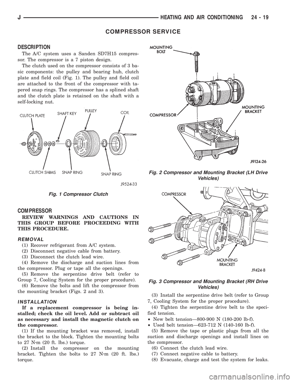
The A/C system uses a Sanden SD7H15 compres-
sor. The compressor is a 7 piston design.
The clutch used on the compressor consists of 3 ba-
sic components: the pulley and bearing hub, clutch
plate and field coil (Fig. 1). The pulley and field coil
are attached to the front of the compressor with ta-
pered snap rings. The compressor has a splined shaft
and the clutch plate is retained on the shaft with a
self-locking nut.
COMPRESSOR
REVIEW WARNINGS AND CAUTIONS IN
THIS GROUP BEFORE PROCEEDING WITH
THIS PROCEDURE.
REMOVAL
(1) Recover refrigerant from A/C system.
(2) Disconnect negative cable from battery.
(3) Disconnect the clutch lead wire.
(4) Remove the discharge and suction lines from
the compressor. Plug or tape all the openings.
(5) Remove the serpentine drive belt (refer to
Group 7, Cooling System for the proper procedure).
(6) Remove the bolts and lift the compressor from
the mounting bracket (Figs. 2 and 3).
INSTALLATION
If a replacement compressor is being in-
stalled; check the oil level. Add or subtract oil
as necessary and install the magnetic clutch on
the compressor.
(1) If the mounting bracket was removed, install
the bracket to the block. Tighten the mounting bolts
to 27 Nzm (20 ft. lbs.) torque.
(2) Install the compressor on the mounting
bracket. Tighten the bolts to 27 Nzm (20 ft. lbs.)
torque.(3) Install the serpentine drive belt (refer to Group
7, Cooling System for the proper procedure).
(4) Tighten the serpentine drive belt to the speci-
fied tension.
²New belt tensionÐ800-900 N (180-200 lb-f).
²Used belt tensionÐ623-712 N (140-160 lb-f).
(5) Remove the tape or plastic plugs from all the
suction and discharge openings and install lines on
the compressor.
(6) Connect the clutch lead wire.
(7) Connect negative cable to battery.
(8) Evacuate, charge and test the system for leaks.
Fig. 1 Compressor Clutch
Fig. 2 Compressor and Mounting Bracket (LH Drive
Vehicles)
Fig. 3 Compressor and Mounting Bracket (RH Drive
Vehicles)
JHEATING AND AIR CONDITIONING 24 - 19
Page 2100 of 2158
COMPRESSOR CLUTCH ASSEMBLY
The compressor clutch can be serviced in the vehi-
cle.
REMOVAL
(1) Remove the serpentine drive belt (refer to
Group 7, Cooling System for the proper procedure).
(2) Remove compressor mounting bolts and lift the
compressor from the mounting bracket. Support the
compressor to work on clutch.
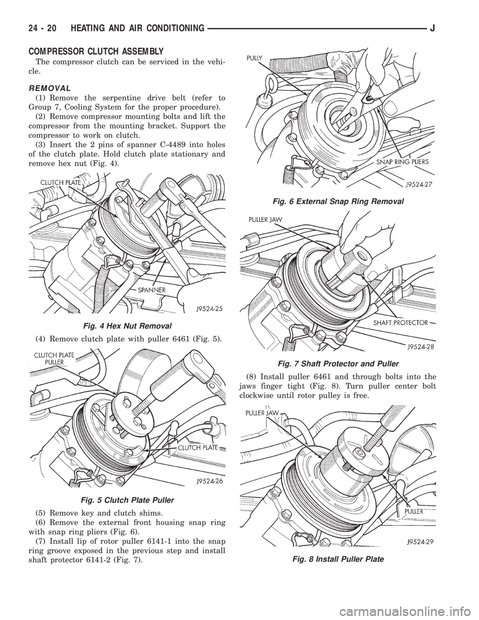
(3) Insert the 2 pins of spanner C-4489 into holes
of the clutch plate. Hold clutch plate stationary and
remove hex nut (Fig. 4).
(4) Remove clutch plate with puller 6461 (Fig. 5).
(5) Remove key and clutch shims.
(6) Remove the external front housing snap ring
with snap ring pliers (Fig. 6).
(7) Install lip of rotor puller 6141-1 into the snap
ring groove exposed in the previous step and install
shaft protector 6141-2 (Fig. 7).(8) Install puller 6461 and through bolts into the
jaws finger tight (Fig. 8). Turn puller center bolt
clockwise until rotor pulley is free.
Fig. 6 External Snap Ring Removal
Fig. 7 Shaft Protector and Puller
Fig. 8 Install Puller Plate
Fig. 4 Hex Nut Removal
Fig. 5 Clutch Plate Puller
24 - 20 HEATING AND AIR CONDITIONINGJ
Page 2106 of 2158
HEATER CORE
REVIEW WARNINGS AND CAUTIONS IN
THIS GROUP BEFORE PERFORMING THIS
OPERATION.
REMOVAL
(1) Drain the radiator.
(2) Disconnect heater hoses at heater core tubes.
(3) Remove heater/evaporator housing side cover.
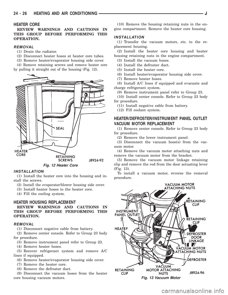
(4) Remove retaining screws and remove heater core
by pulling it straight out of the housing (Fig. 12).
INSTALLATION
(1) Install the heater core into the housing and in-
stall the screws.
(2) Install the evaporator/blower housing side cover.
(3) Install heater hoses to the heater core.
(4) Fill the cooling system.
HEATER HOUSING REPLACEMENT
REVIEW WARNINGS AND CAUTIONS IN
THIS GROUP BEFORE PERFORMING THIS
OPERATION.
REMOVAL
(1) Disconnect negative cable from battery.
(2) Remove center console. Refer to Group 23 body
for procedure.
(3) Remove instrument panel refer to Group 23.
(4) Remove heater hoses.
(5) Recover refrigerant system and remove A/C
lines if equipped.
(6) Remove heater/evaporator housing side cover.
(7) Remove the heater core.
(8) Remove the defroster duct.
(9) Disconnect the vacuum hoses from the heater
core housing vacuum motors.(10) Remove the housing retaining nuts in the en-
gine compartment. Remove the heater core housing.
INSTALLATION
(1) Transfer the vacuum motors, etc. to the re-
placement housing.
(2) Install the heater core housing and heater
housing retaining nuts in the engine compartment.
(3) Install the vacuum hoses.
(4) Install the defroster duct.
(5) Install the heater core.
(6) Install heater/evaporator housing side cover.
(7) Remove heater hoses.
(8) Install A/C lines if equipped and evacuate and
charge refrigerant system.
(9) Remove instrument panel refer to Group 23.
(10) Install center console. Refer to Group 23 body
for procedure.
(11) Install negative cable from battery.
(12) Fill coolant system.
HEATER/DEFROSTER/INSTRUMENT PANEL OUTLET
VACUUM MOTOR REPLACEMENT
(1) Remove center console. Refer to Group 23 body
for procedure.
(2) Remove the lower instrument panel.
(3) Disconnect the vacuum hose(s) from the vac-
uum motor.
(4) Remove the vacuum motor attaching nuts and
remove the vacuum motor from the bracket.
(5) Remove the vacuum motor linkage retaining
clip and remove the rod from the door actuating lever
(Fig. 13).
To install a vacuum motor, reverse the removal
procedure.
Fig. 12 Heater Core
Fig. 13 Vacuum Motor
24 - 26 HEATING AND AIR CONDITIONINGJ
Page 2107 of 2158
A/C RECIRCULATING DOOR VACUUM MOTOR
REPLACEMENT
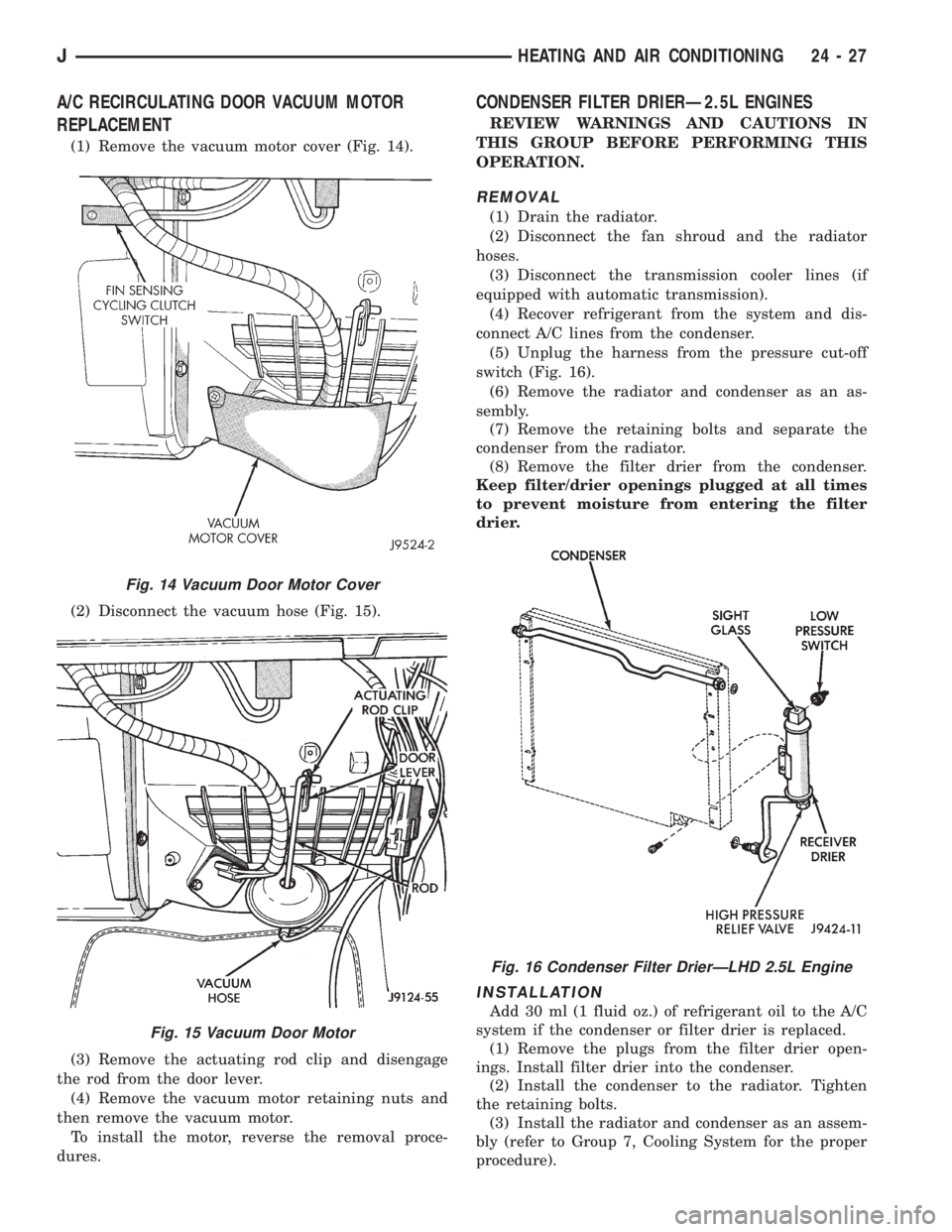
(1) Remove the vacuum motor cover (Fig. 14).
(2) Disconnect the vacuum hose (Fig. 15).
(3) Remove the actuating rod clip and disengage
the rod from the door lever.
(4) Remove the vacuum motor retaining nuts and
then remove the vacuum motor.
To install the motor, reverse the removal proce-
dures.
CONDENSER FILTER DRIERÐ2.5L ENGINES
REVIEW WARNINGS AND CAUTIONS IN
THIS GROUP BEFORE PERFORMING THIS
OPERATION.
REMOVAL
(1) Drain the radiator.
(2) Disconnect the fan shroud and the radiator
hoses.
(3) Disconnect the transmission cooler lines (if
equipped with automatic transmission).
(4) Recover refrigerant from the system and dis-
connect A/C lines from the condenser.
(5) Unplug the harness from the pressure cut-off
switch (Fig. 16).
(6) Remove the radiator and condenser as an as-
sembly.
(7) Remove the retaining bolts and separate the
condenser from the radiator.
(8) Remove the filter drier from the condenser.
Keep filter/drier openings plugged at all times
to prevent moisture from entering the filter
drier.
INSTALLATION
Add 30 ml (1 fluid oz.) of refrigerant oil to the A/C
system if the condenser or filter drier is replaced.
(1) Remove the plugs from the filter drier open-
ings. Install filter drier into the condenser.
(2) Install the condenser to the radiator. Tighten
the retaining bolts.
(3) Install the radiator and condenser as an assem-
bly (refer to Group 7, Cooling System for the proper
procedure).
Fig. 14 Vacuum Door Motor Cover
Fig. 15 Vacuum Door Motor
Fig. 16 Condenser Filter DrierÐLHD 2.5L Engine
JHEATING AND AIR CONDITIONING 24 - 27