1995 JEEP YJ cooling
[x] Cancel search: coolingPage 1431 of 2158
coolant temperature drops to 98ÉC (208ÉF). Refer to
Group 7, Cooling Systems for more information.
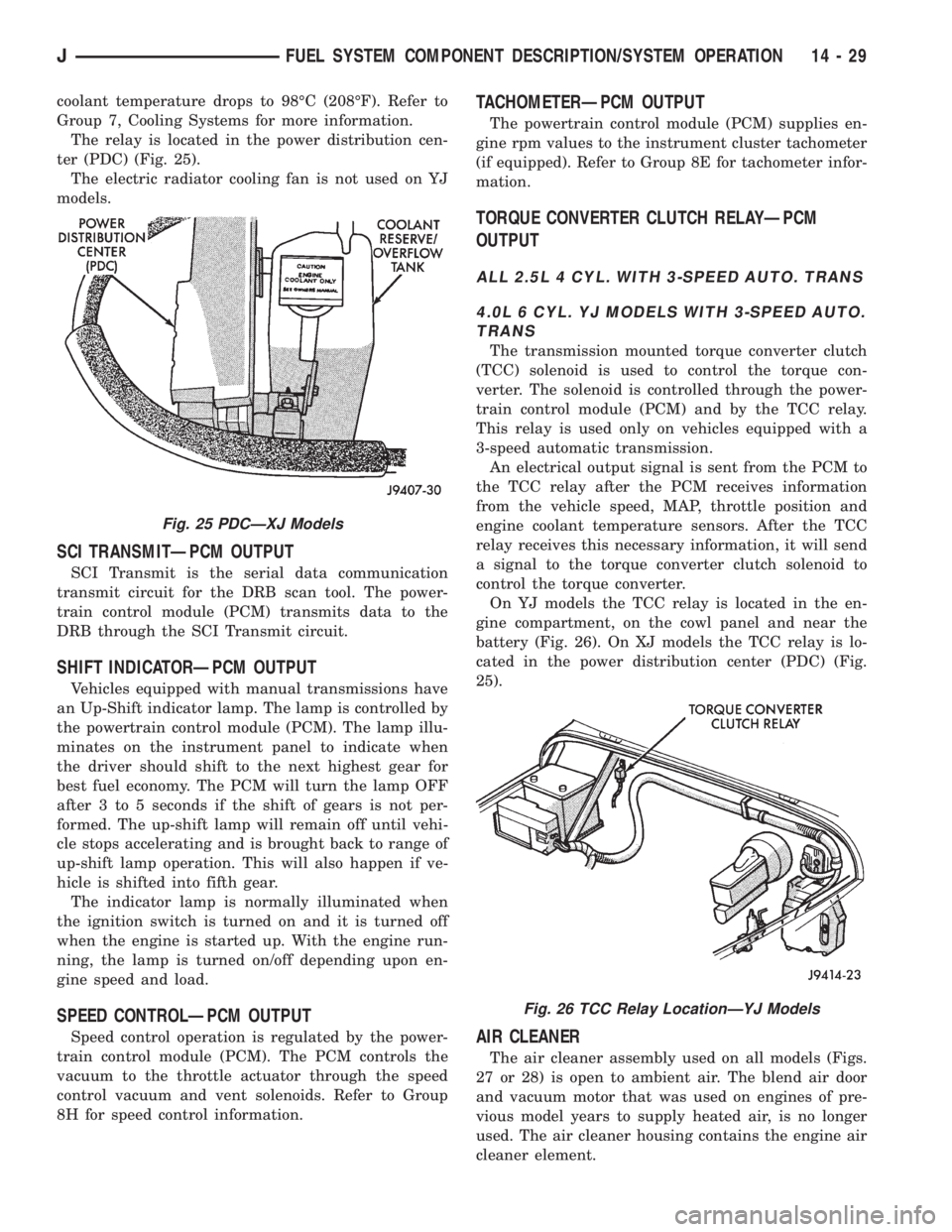
The relay is located in the power distribution cen-
ter (PDC) (Fig. 25).
The electric radiator cooling fan is not used on YJ
models.
SCI TRANSMITÐPCM OUTPUT
SCI Transmit is the serial data communication
transmit circuit for the DRB scan tool. The power-
train control module (PCM) transmits data to the
DRB through the SCI Transmit circuit.
SHIFT INDICATORÐPCM OUTPUT
Vehicles equipped with manual transmissions have
an Up-Shift indicator lamp. The lamp is controlled by
the powertrain control module (PCM). The lamp illu-
minates on the instrument panel to indicate when
the driver should shift to the next highest gear for
best fuel economy. The PCM will turn the lamp OFF
after 3 to 5 seconds if the shift of gears is not per-
formed. The up-shift lamp will remain off until vehi-
cle stops accelerating and is brought back to range of
up-shift lamp operation. This will also happen if ve-
hicle is shifted into fifth gear.
The indicator lamp is normally illuminated when
the ignition switch is turned on and it is turned off
when the engine is started up. With the engine run-
ning, the lamp is turned on/off depending upon en-
gine speed and load.
SPEED CONTROLÐPCM OUTPUT
Speed control operation is regulated by the power-
train control module (PCM). The PCM controls the
vacuum to the throttle actuator through the speed
control vacuum and vent solenoids. Refer to Group
8H for speed control information.
TACHOMETERÐPCM OUTPUT
The powertrain control module (PCM) supplies en-
gine rpm values to the instrument cluster tachometer
(if equipped). Refer to Group 8E for tachometer infor-
mation.
TORQUE CONVERTER CLUTCH RELAYÐPCM
OUTPUT
ALL 2.5L 4 CYL. WITH 3-SPEED AUTO. TRANS
4.0L 6 CYL. YJ MODELS WITH 3-SPEED AUTO.
TRANS
The transmission mounted torque converter clutch
(TCC) solenoid is used to control the torque con-
verter. The solenoid is controlled through the power-
train control module (PCM) and by the TCC relay.
This relay is used only on vehicles equipped with a
3-speed automatic transmission.
An electrical output signal is sent from the PCM to
the TCC relay after the PCM receives information
from the vehicle speed, MAP, throttle position and
engine coolant temperature sensors. After the TCC
relay receives this necessary information, it will send
a signal to the torque converter clutch solenoid to
control the torque converter.
On YJ models the TCC relay is located in the en-
gine compartment, on the cowl panel and near the
battery (Fig. 26). On XJ models the TCC relay is lo-
cated in the power distribution center (PDC) (Fig.
25).
AIR CLEANER
The air cleaner assembly used on all models (Figs.
27 or 28) is open to ambient air. The blend air door
and vacuum motor that was used on engines of pre-
vious model years to supply heated air, is no longer
used. The air cleaner housing contains the engine air
cleaner element.
Fig. 25 PDCÐXJ Models
Fig. 26 TCC Relay LocationÐYJ Models
JFUEL SYSTEM COMPONENT DESCRIPTION/SYSTEM OPERATION 14 - 29
Page 1439 of 2158
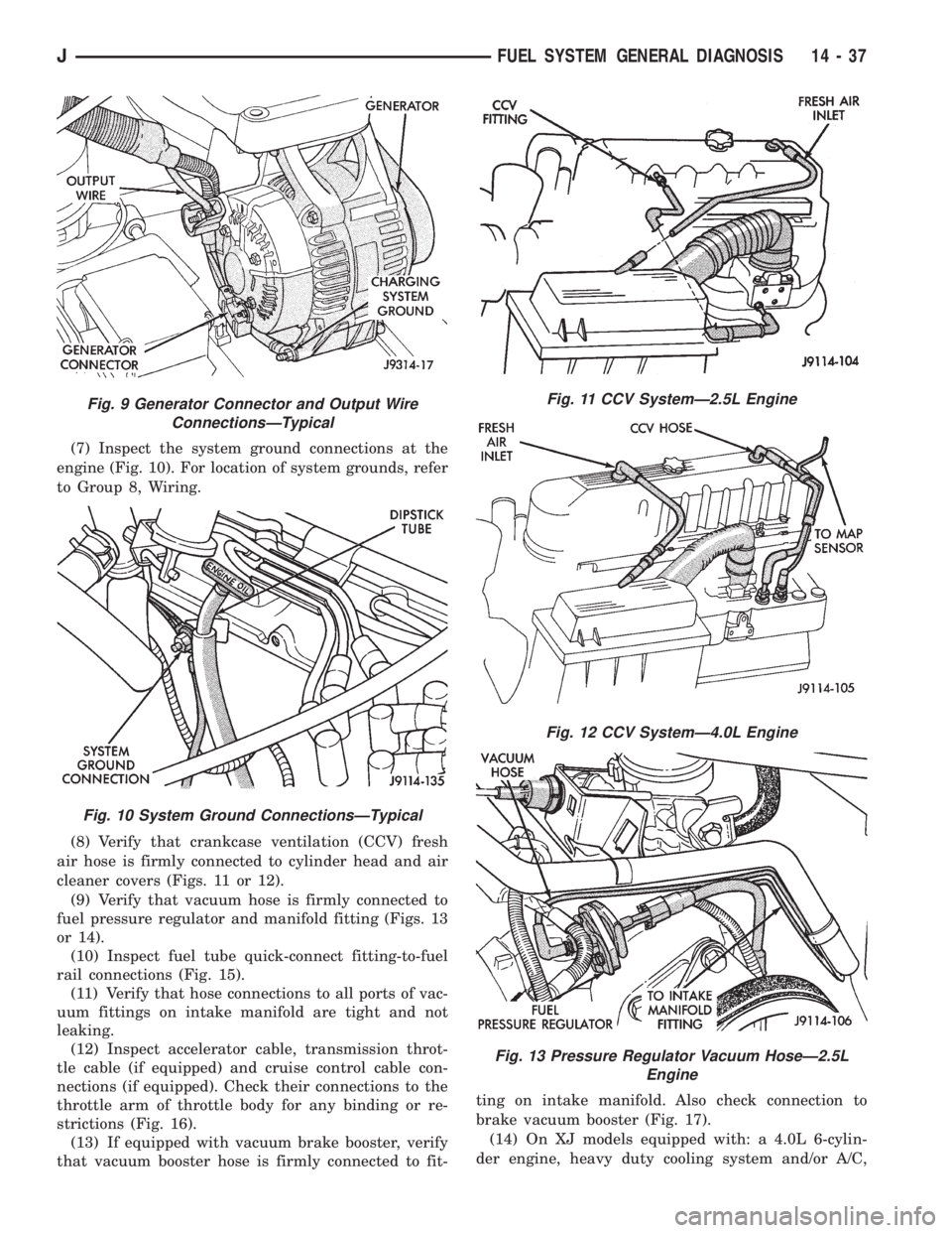
(7) Inspect the system ground connections at the
engine (Fig. 10). For location of system grounds, refer
to Group 8, Wiring.
(8) Verify that crankcase ventilation (CCV) fresh
air hose is firmly connected to cylinder head and air
cleaner covers (Figs. 11 or 12).
(9) Verify that vacuum hose is firmly connected to
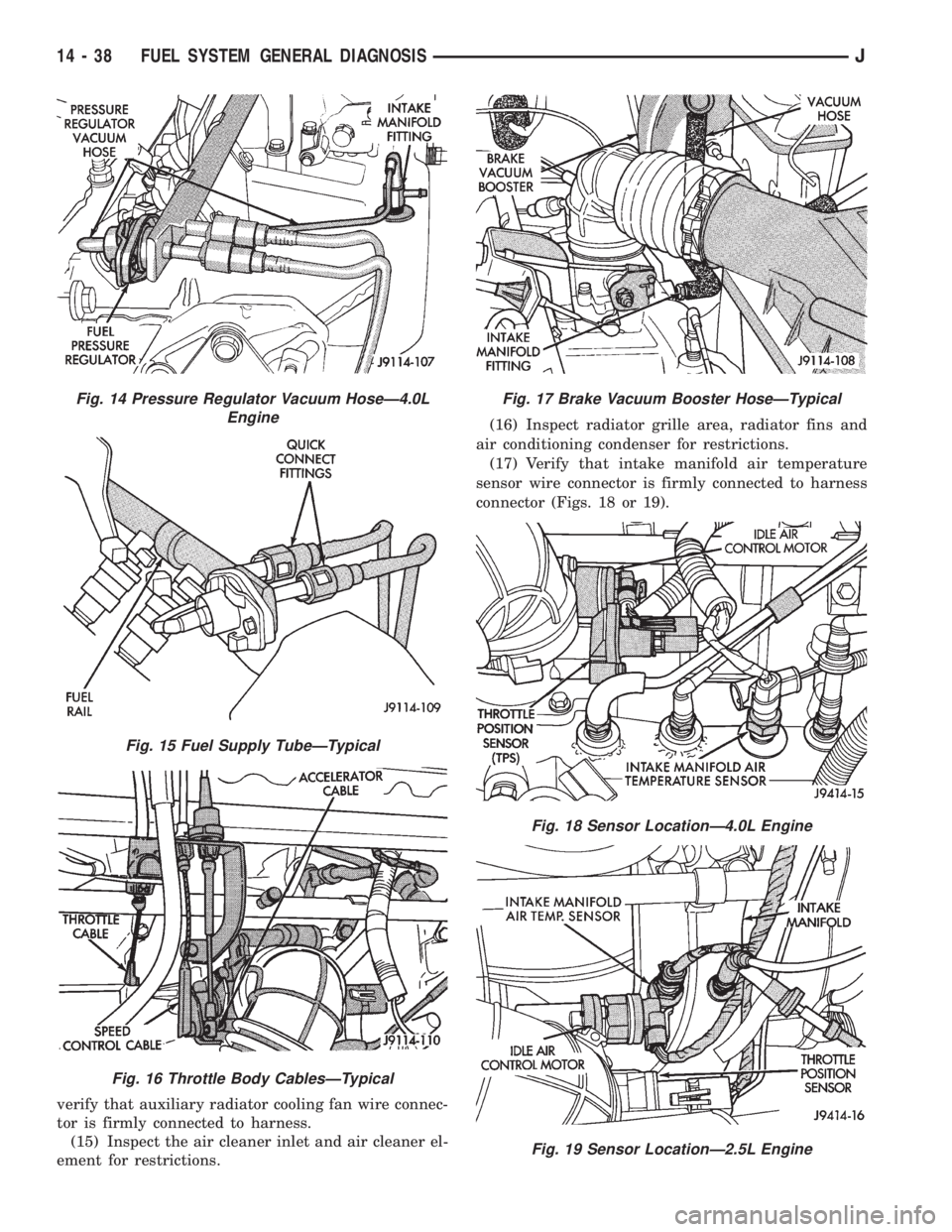
fuel pressure regulator and manifold fitting (Figs. 13
or 14).
(10) Inspect fuel tube quick-connect fitting-to-fuel
rail connections (Fig. 15).
(11) Verify that hose connections to all ports of vac-
uum fittings on intake manifold are tight and not
leaking.
(12) Inspect accelerator cable, transmission throt-
tle cable (if equipped) and cruise control cable con-
nections (if equipped). Check their connections to the
throttle arm of throttle body for any binding or re-
strictions (Fig. 16).
(13) If equipped with vacuum brake booster, verify
that vacuum booster hose is firmly connected to fit-ting on intake manifold. Also check connection to
brake vacuum booster (Fig. 17).
(14) On XJ models equipped with: a 4.0L 6-cylin-
der engine, heavy duty cooling system and/or A/C,
Fig. 9 Generator Connector and Output Wire
ConnectionsÐTypical
Fig. 10 System Ground ConnectionsÐTypical
Fig. 11 CCV SystemÐ2.5L Engine
Fig. 12 CCV SystemÐ4.0L Engine
Fig. 13 Pressure Regulator Vacuum HoseÐ2.5L
Engine
JFUEL SYSTEM GENERAL DIAGNOSIS 14 - 37
Page 1440 of 2158
verify that auxiliary radiator cooling fan wire connec-
tor is firmly connected to harness.
(15) Inspect the air cleaner inlet and air cleaner el-
ement for restrictions.(16) Inspect radiator grille area, radiator fins and
air conditioning condenser for restrictions.
(17) Verify that intake manifold air temperature
sensor wire connector is firmly connected to harness
connector (Figs. 18 or 19).
Fig. 14 Pressure Regulator Vacuum HoseÐ4.0L
Engine
Fig. 15 Fuel Supply TubeÐTypical
Fig. 16 Throttle Body CablesÐTypical
Fig. 17 Brake Vacuum Booster HoseÐTypical
Fig. 18 Sensor LocationÐ4.0L Engine
Fig. 19 Sensor LocationÐ2.5L Engine
14 - 38 FUEL SYSTEM GENERAL DIAGNOSISJ
Page 1451 of 2158
IDLE AIR CONTROL MOTOR TEST
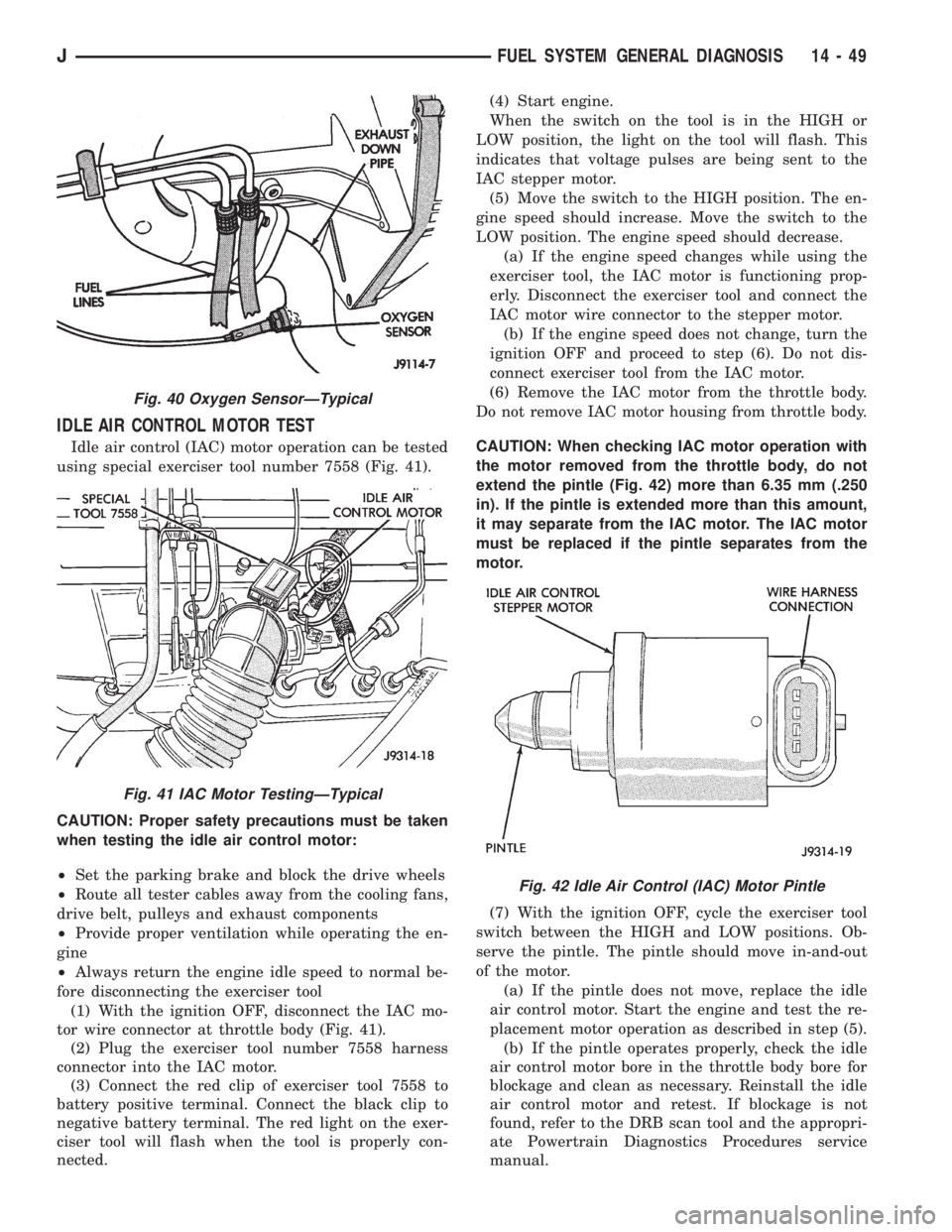
Idle air control (IAC) motor operation can be tested
using special exerciser tool number 7558 (Fig. 41).
CAUTION: Proper safety precautions must be taken
when testing the idle air control motor:
²Set the parking brake and block the drive wheels
²Route all tester cables away from the cooling fans,
drive belt, pulleys and exhaust components
²Provide proper ventilation while operating the en-
gine
²Always return the engine idle speed to normal be-
fore disconnecting the exerciser tool
(1) With the ignition OFF, disconnect the IAC mo-
tor wire connector at throttle body (Fig. 41).
(2) Plug the exerciser tool number 7558 harness
connector into the IAC motor.
(3) Connect the red clip of exerciser tool 7558 to
battery positive terminal. Connect the black clip to
negative battery terminal. The red light on the exer-
ciser tool will flash when the tool is properly con-
nected.(4) Start engine.
When the switch on the tool is in the HIGH or
LOW position, the light on the tool will flash. This
indicates that voltage pulses are being sent to the
IAC stepper motor.
(5) Move the switch to the HIGH position. The en-
gine speed should increase. Move the switch to the
LOW position. The engine speed should decrease.
(a) If the engine speed changes while using the
exerciser tool, the IAC motor is functioning prop-
erly. Disconnect the exerciser tool and connect the
IAC motor wire connector to the stepper motor.
(b) If the engine speed does not change, turn the
ignition OFF and proceed to step (6). Do not dis-
connect exerciser tool from the IAC motor.
(6) Remove the IAC motor from the throttle body.
Do not remove IAC motor housing from throttle body.
CAUTION: When checking IAC motor operation with
the motor removed from the throttle body, do not
extend the pintle (Fig. 42) more than 6.35 mm (.250
in). If the pintle is extended more than this amount,
it may separate from the IAC motor. The IAC motor
must be replaced if the pintle separates from the
motor.
(7) With the ignition OFF, cycle the exerciser tool
switch between the HIGH and LOW positions. Ob-
serve the pintle. The pintle should move in-and-out
of the motor.
(a) If the pintle does not move, replace the idle
air control motor. Start the engine and test the re-
placement motor operation as described in step (5).
(b) If the pintle operates properly, check the idle
air control motor bore in the throttle body bore for
blockage and clean as necessary. Reinstall the idle
air control motor and retest. If blockage is not
found, refer to the DRB scan tool and the appropri-
ate Powertrain Diagnostics Procedures service
manual.
Fig. 40 Oxygen SensorÐTypical
Fig. 41 IAC Motor TestingÐTypical
Fig. 42 Idle Air Control (IAC) Motor Pintle
JFUEL SYSTEM GENERAL DIAGNOSIS 14 - 49
Page 1462 of 2158
CAMSHAFT POSITION SENSOR
For removal/installation procedures, refer to Group
8D, Ignition System. See Camshaft Position Sensor.
INTAKE MANIFOLD AIR TEMPERATURE SENSOR
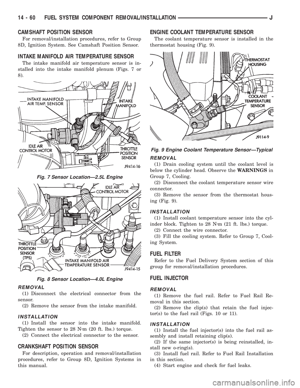
The intake manifold air temperature sensor is in-
stalled into the intake manifold plenum (Figs. 7 or
8).
REMOVAL
(1) Disconnect the electrical connector from the
sensor.
(2) Remove the sensor from the intake manifold.
INSTALLATION
(1) Install the sensor into the intake manifold.
Tighten the sensor to 28 Nzm (20 ft. lbs.) torque.
(2) Connect the electrical connector to the sensor.
CRANKSHAFT POSITION SENSOR
For description, operation and removal/installation
procedures, refer to Group 8D, Ignition Systems in
this manual.
ENGINE COOLANT TEMPERATURE SENSOR
The coolant temperature sensor is installed in the
thermostat housing (Fig. 9).
REMOVAL
(1) Drain cooling system until the coolant level is
below the cylinder head. Observe theWARNINGSin
Group 7, Cooling.
(2) Disconnect the coolant temperature sensor wire
connector.
(3) Remove the sensor from the thermostat hous-
ing (Fig. 9).
INSTALLATION
(1) Install coolant temperature sensor into the cyl-
inder block. Tighten to 28 Nzm (21 ft. lbs.) torque.
(2) Connect the wire connector.
(3) Fill the cooling system. Refer to Group 7, Cool-
ing System.
FUEL FILTER
Refer to the Fuel Delivery System section of this
group for removal/installation procedures.
FUEL INJECTOR
REMOVAL
(1) Remove the fuel rail. Refer to Fuel Rail Re-
moval in this section.
(2) Remove the clip(s) that retain the fuel injec-
tor(s) to the fuel rail (Figs. 10 or 11).
INSTALLATION
(1) Install the fuel injector(s) into the fuel rail as-
sembly and install retaining clip(s).
(2) If the same injector(s) is being reinstalled, in-
stall new o-ring(s).
(3) Install fuel rail. Refer to Fuel Rail Installation
in this section.
(4) Start engine and check for fuel leaks.
Fig. 7 Sensor LocationÐ2.5L Engine
Fig. 8 Sensor LocationÐ4.0L Engine
Fig. 9 Engine Coolant Temperature SensorÐTypical
14 - 60 FUEL SYSTEM COMPONENT REMOVAL/INSTALLATIONJ
Page 1496 of 2158
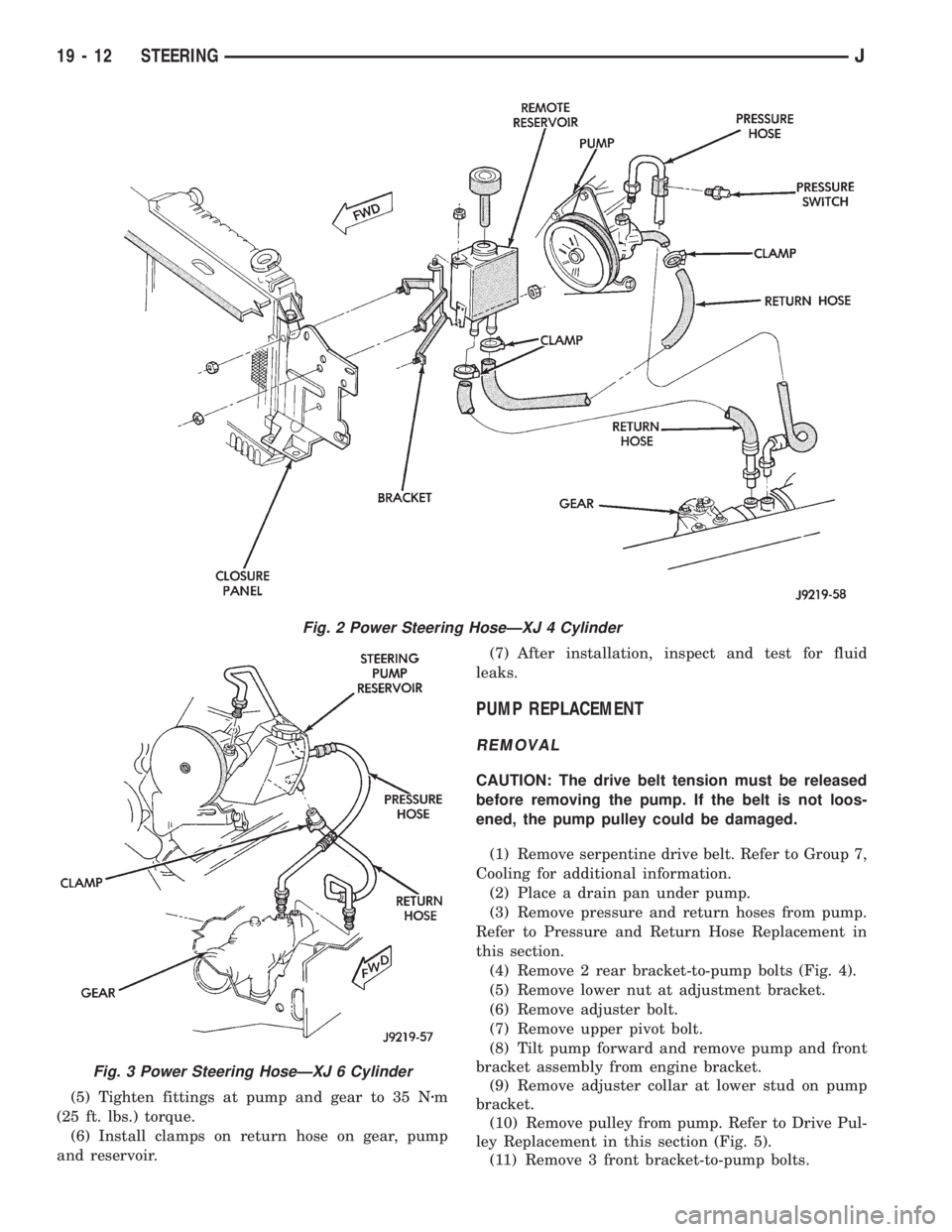
(5) Tighten fittings at pump and gear to 35 Nzm
(25 ft. lbs.) torque.
(6) Install clamps on return hose on gear, pump
and reservoir.(7) After installation, inspect and test for fluid
leaks.
PUMP REPLACEMENT
REMOVAL
CAUTION: The drive belt tension must be released
before removing the pump. If the belt is not loos-
ened, the pump pulley could be damaged.
(1) Remove serpentine drive belt. Refer to Group 7,
Cooling for additional information.
(2) Place a drain pan under pump.
(3) Remove pressure and return hoses from pump.
Refer to Pressure and Return Hose Replacement in
this section.
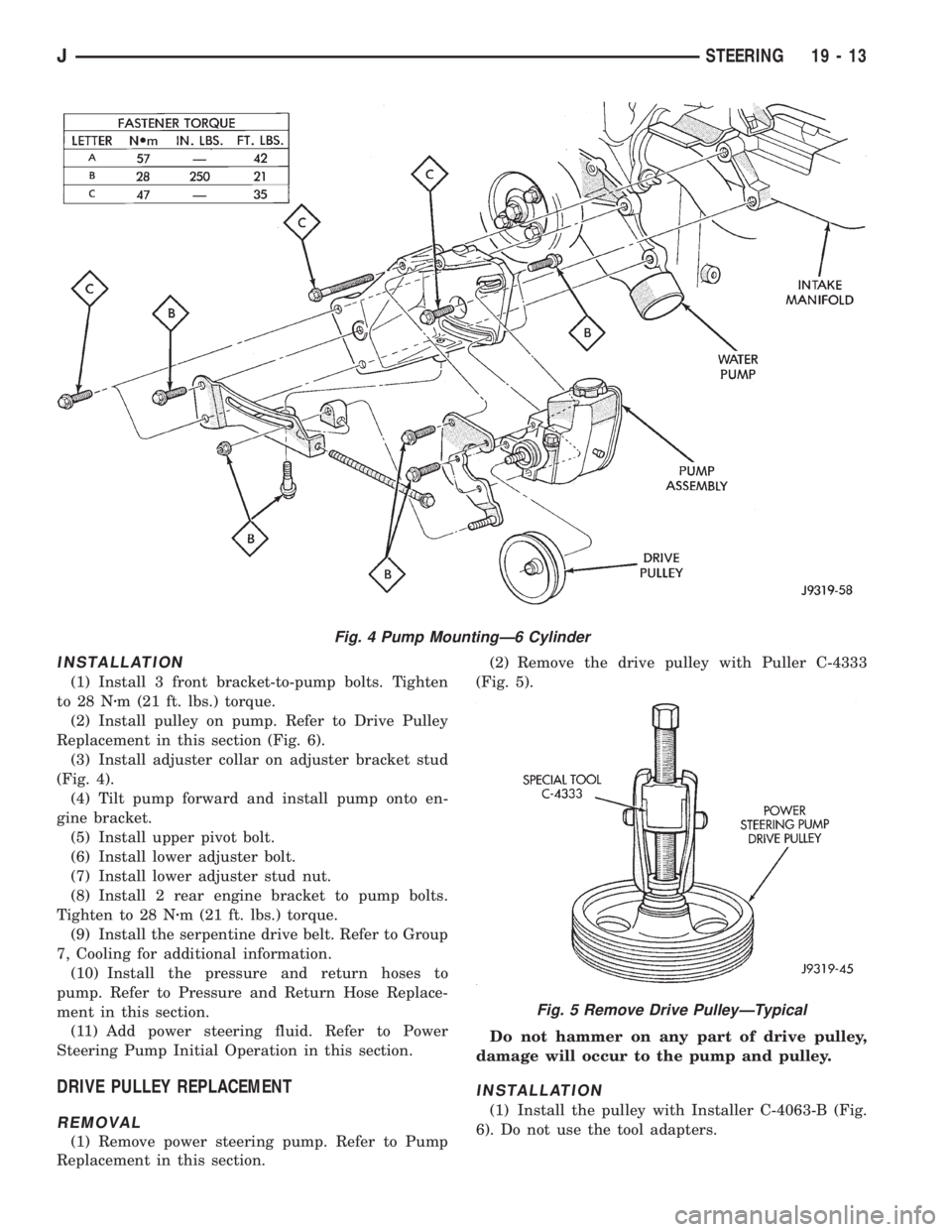
(4) Remove 2 rear bracket-to-pump bolts (Fig. 4).
(5) Remove lower nut at adjustment bracket.
(6) Remove adjuster bolt.
(7) Remove upper pivot bolt.
(8) Tilt pump forward and remove pump and front
bracket assembly from engine bracket.
(9) Remove adjuster collar at lower stud on pump
bracket.
(10) Remove pulley from pump. Refer to Drive Pul-
ley Replacement in this section (Fig. 5).
(11) Remove 3 front bracket-to-pump bolts.
Fig. 2 Power Steering HoseÐXJ 4 Cylinder
Fig. 3 Power Steering HoseÐXJ 6 Cylinder
19 - 12 STEERINGJ
Page 1497 of 2158
INSTALLATION
(1) Install 3 front bracket-to-pump bolts. Tighten
to 28 Nzm (21 ft. lbs.) torque.
(2) Install pulley on pump. Refer to Drive Pulley
Replacement in this section (Fig. 6).
(3) Install adjuster collar on adjuster bracket stud
(Fig. 4).
(4) Tilt pump forward and install pump onto en-
gine bracket.
(5) Install upper pivot bolt.
(6) Install lower adjuster bolt.
(7) Install lower adjuster stud nut.
(8) Install 2 rear engine bracket to pump bolts.
Tighten to 28 Nzm (21 ft. lbs.) torque.
(9) Install the serpentine drive belt. Refer to Group
7, Cooling for additional information.
(10) Install the pressure and return hoses to
pump. Refer to Pressure and Return Hose Replace-
ment in this section.
(11) Add power steering fluid. Refer to Power
Steering Pump Initial Operation in this section.
DRIVE PULLEY REPLACEMENT
REMOVAL
(1) Remove power steering pump. Refer to Pump
Replacement in this section.(2) Remove the drive pulley with Puller C-4333
(Fig. 5).
Do not hammer on any part of drive pulley,
damage will occur to the pump and pulley.
INSTALLATION
(1) Install the pulley with Installer C-4063-B (Fig.
6). Do not use the tool adapters.
Fig. 4 Pump MountingÐ6 Cylinder
Fig. 5 Remove Drive PulleyÐTypical
JSTEERING 19 - 13
Page 1995 of 2158
TRAILER HITCH
TRAILER HITCHÐXJ
CLASS III HITCH
A class III weight-distributing/equalizer type hitch
can be used to tow a trailer:
²Having a maximum gross weight of 5,000 lbs/2250
kg.
²Having a maximum tongue weight of 750 lbs/332
kg).
The following vehicle basic equipment is required
for class III trailer towing:
²P205/75R15 or larger tires.
²Full size spare tire.
²Trailer sway control.
²Trailer tow wire harness and connector.
²Heavy duty turn signal flasher element.
²Heavy duty axle (with synthetic lubricant).
²Heavy duty cooling system.
²Heavy duty generator/battery.
²Auxiliary automatic transmission fluid cooler.
²I-6, 4.0L engine.
Wide-angle type door mirrors are recommended but
not required.
WIRE HARNESS CONNECTORS
CLASS I HITCH CONNECTOR
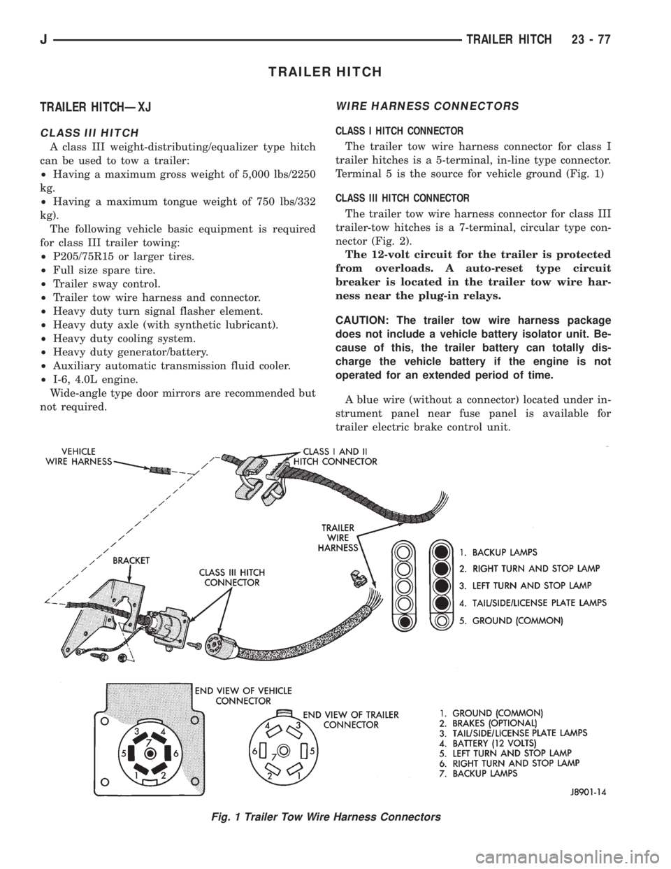
The trailer tow wire harness connector for class I
trailer hitches is a 5-terminal, in-line type connector.
Terminal 5 is the source for vehicle ground (Fig. 1)
CLASS III HITCH CONNECTOR
The trailer tow wire harness connector for class III
trailer-tow hitches is a 7-terminal, circular type con-
nector (Fig. 2).
The 12-volt circuit for the trailer is protected
from overloads. A auto-reset type circuit
breaker is located in the trailer tow wire har-
ness near the plug-in relays.
CAUTION: The trailer tow wire harness package
does not include a vehicle battery isolator unit. Be-
cause of this, the trailer battery can totally dis-
charge the vehicle battery if the engine is not
operated for an extended period of time.
A blue wire (without a connector) located under in-
strument panel near fuse panel is available for
trailer electric brake control unit.
Fig. 1 Trailer Tow Wire Harness Connectors
JTRAILER HITCH 23 - 77